Upgrade to Pro — share decks privately, control downloads, hide ads and more …

Basic_Information_on_Satellite_Observation_Technology.pdf

 Basic_Information_on_Satellite_Observation_Technology.pdf

data_rikatsuyou

October 31, 2022
Tweet

More Decks by data_rikatsuyou

Other Decks in Business

Transcript

  1. About this document 1 ◼ This document summarizes basic information

    on satellite remote sensing (observation technology) for the implementation of the "Verification of Advanced Predictive Detection Using Satellite Data," a beta version of the Digital Twin Realization Project. ◼ Since the purpose of this verification is to validate the possibility of using satellite data for disaster management, this document focuses on optical and SAR satellites, which are expected to be utilized in disaster management. ◼ Please note that technical terms in the documents are used in a simple and easy-to-understand manner, and may have different meanings in some cases.
  2. main items # main items Overview of Satellite Remote Sensing

    5 What is Remote Sensing? 6 Electromagnetic waves observed by satellite remote sensing sensors 7 Advantages and disadvantages of satellite remote sensing 8 Types of satellite remote sensing sensors 9 Differences between optical and SAR satellites Observation method of satellite remote sensing 11 Satellite remote sensing observations 12 Areas to be observed by satellite remote sensing 13 Flow of satellite remote sensing data from observation to acquisition Overview of Optical Satellite 15 What is an Optical Satellite? 16 Composition of optical satellite data 17 Analysis of optical satellite data using bands Case Study of Optical Satellite Analysis 19 Vegetation Mapping 20 Extraction of inundation area 21 3D mapping of terrain and cities 22 Automatic detection of artifacts 23 Assessing land use conditions Table of Contents 2
  3. main items # main items Overview of SAR Satellite 25

    What is a SAR satellite? 26 Composition of SAR satellite data 27 Main analysis methods for SAR satellite data 28 Types of electromagnetic waves used in SAR satellites Examples of SAR Satellite Analysis 30 Extraction of the areas of the ground surface change 31 Spatial understanding of ground deformation 33 Surveillance on vessels 34 Extraction of leakage areas Satellite Applications to Disasters 36 Satellite applicability to disasters 37 Examples of Satellite Applications to Domestic Disasters Other Information 39 Satellite Data Pricing 40 Examples of Private Remote Sensing Satellite Operators 41 Reference Links Table of Contents 3
  4. What is Remote Sensing? 5 Technology that enables the observation

    of an object without directly touching it ◼ Remote sensing is a general term for the technology that enables the observation of an object without touching it ◼ Satellite remote sensing is performed by installing a dedicated sensor on a satellite. ◼ Dedicated sensors may be mounted on aircraft, drones, etc. ◼ Sensors that perform satellite remote sensing observe electromagnetic waves emitted or reflected from the earth's surface and the ocean's surface Source:https://www.semanticscholar.org/paper/Mini-Unmanned-Aerial-Vehicle-Based- Remote-Sensing%3A-Xiang-Xia/cf65f7bf07e800d26a629982ffa5cc7b182498f7/figure/0 Satellite Remote Sensing
  5. Electromagnetic waves observed by satellite remote sensing sensors 6 Observe

    electromagnetic waves radiated and reflected from the earth and sea surfaces ◼ Satellite remote sensing sensors observe electromagnetic waves emitted or reflected from the earth's surface or sea surface. ➢ Observe electromagnetic waves radiated from the earth's surface and sea surface due to heat, etc. ➢ Observe the reflection of electromagnetic waves emitted from the earth's surface and sea surface by the sun's rays and satellites ◼ There are various types (bands) of electromagnetic waves, and each sensor can observe different electromagnetic waves ➢ Each type of electromagnetic wave may have a name. ➢ For example, there are visible light (electromagnetic wave range visible to the naked eye), ultraviolet rays, infrared rays, etc. Source:Division of Biomolecular Sciences, Toho University Satellite (camera and sensor) Source:JAXA "Utilization of Satellite Data" document Wavelength(m) Wavelength of visible light(nm) radio wave microwave infrared Ultraviolet (UV) X-ray gamma ray atmosphere radiation radiation radiation reflection reflection
  6. Advantages ◼ Observation from space (high altitude) enables observation of

    a much wider area than with aircraft, drones, etc. ◼ Less subject to restrictions imposed by laws and regulations on the ground, making it easy to target remote areas such as overseas lands, and also easy to perform multiple observations Disadvantages /Drawbacks ◼ Observations are made from space, so they are relatively coarse in terms of accuracy. ◼ (Although the frequency has tended to increase in recent years), the same location is observed every few days to a few weeks. Basically, satellites can only observe the ground surface, and it is difficult to observe the conditions underground or under the sea. Advantages and disadvantages of satellite remote sensing 7 Compared to ground-based observation methods (drones, field surveys, etc.) Satellite remote sensing has advantages and disadvantages
  7. Satellite remote sensing sensor types 8 There are four major

    types of satellite remote sensing sensors type Main types of electromagnetic waves to be observed Information to be obtained Optical Sensors Visible/Near-infrared Images of ground surface Thermal infrared sensor Infra-red rays Heat distribution on the ground surface Microwave radiometer Microwave Sea surface temperature, water vapor, etc. SAR sensor (Synthetic Aperture Radar) Microwave Images of ground surface ◼ There are four major types of sensors for satellite remote sensing, and the types of electromagnetic waves to be observed and the information to be obtained differ because of the different electromagnetic waves to be targeted. ◼ Optical and SAR sensors are increasingly being used in the disaster and disaster prevention. Because they are more able to detect disasters and provide many options for data acquisition in the public and private sectors.
  8. Differences between optical and SAR satellites Source:http://www.nilim.go.jp/lab/bcg/siryou/tnn/tnn0760pdf/ks076005.pdf The characteristics of

    the data obtained are different because of the different means used ◼ Optical and SAR sensors are similar in the sense that they acquire "images of the earth's surface," but they have different observation principles and characteristics. ◼ The figure below shows an example of the same area observed by a SAR satellite and an optical satellite. Example of optical satellite image Example of SAR satellite image type Principles of observation of electromagneti c waves Characteristics of the information obtained Optical Sensor Observe reflection and emission of electromagnetic waves from the sun ◼ Aerial photo-like images for easy understanding ◼ Cannot be observed under clouds or at night SAR Sensor Emit electromagnetic waves from a satellite and observes the reflected waves on the earth's surface ◼ The distinctively patterned pictures can be hard to interpret ◼ Observation is possible regardless of weather, day or night 9 Akadani Akadani Nagatono Nagatono Ui Ui
  9. Satellite remote sensing observations 11 ◼ Satellites make observations as

    they orbit the Earth. ◼ The satellite's sensors are controlled to point toward the earth for observation, so that they observe the area directly below the satellite's path. ◼ Satellites pass through orbits that rotate north and south (e.g., polar orbits) and can observe the entire globe as the earth rotates on its axis. ◼ The altitude is about 600 km above the earth's surface. ◼ Satellite with optical and SAR sensors is powered by solar panels. Satellites observe while orbiting the Earth. Source:https://sorabatake.jp/802/ polar orbit
  10. Areas to be observed by satellite remote sensing 12 ◼

    The area observed by the satellite would be under the satellite's path. ◼ The width of the band is called the “swath," which varies from tens to hundreds of kilometers for each satellite. ◼ Observed bands are often cut into units called "scenes" (sometimes used as a unit for the number of images) ◼ The term "spatial resolution" is used to describe the degree to which a scene can be seen in detail (the smaller the value, the higher the resolution) ◼ Observation width, scene, and spatial resolution vary from satellite to satellite The area to be observed is zonal Source:https://www.restec.or.jp/knowledge/sensing/sensing-3.html Satellite Orbit Observed in a band Spatial resolution (1 scene) Observation Width Observation Width Viewed from a satellite
  11. ③reception Flow of satellite remote sensing data from observation to

    acquisition 13 There are four steps from observation to data provision ground station Object of observation receiving post office Satellite Data Analysis Operators user satellite ◼ There are four steps to obtaining satellite observation data 1) Observation request 2) Observation 3) Receipt of observation data (downlink) 4) Provision of observation data ◼ Each satellite is different, but each step takes time 1) Requests for observations may need to be made several weeks or more in advance 2) One satellite can only observe the same location at intervals of one day to several weeks or more (multiple satellites can be used) 3) Reception itself is time-consuming and requires preprocessing time for use as satellite images. ◼ At the point, it will take several hours or more in general to obtain satellite data after the observation. ➢ The time required for each step is being reduced. ①Observation Request ②observation ④data distribution
  12. What is an Optical Satellite? 15 The resulting image is

    close to a photograph, allowing for easy-to-understand observations. ◼ Optical Satellites are satellites equipped with optical sensors and mainly observe electromagnetic waves in the visible light range. ◼ The resulting image is similar to a photograph and can be handled like an aerial photograph without prerequisite knowledge. ◼ Observation opportunities are limited to the daytime when the sun is in the sky, and cloud cover hinders observation of the ground surface. ◼ Maxar's WorldView series is a well-known example in this case ◼ Satellites with higher spatial resolution (higher resolution) tend to be more expensive Source:https://www.restec.or.jp/satellite/worldview-3.html Source: https://content.satimagingcorp.com/static/galleryimages/WorldV iew-4-Satellite-Image-30cm-Gymnasium-Tokyo.jpg Example of optical satellite image WorldView-3 Satellite
  13. Composition of optical satellite data Optical satellite data is observed

    separately for each electromagnetic wave (band) Blue band Contents of optical satellite data Green band Red band Infrared band ◼ Optical satellite data is observed separately for each type of electromagnetic wave (band)Blue, Red, and Green, which are visible light rays, can be used to create an aerial photograph-like image. ◼ Blue, red, and green, which are visible light rays, can be used to create an aerial photograph-like image. ◼ Electromagnetic waves other than visible light are also observed separately, enabling the extraction of invisible information. Composite RGB looks like a photograph … Synthesis example 16 • Lots more than just RGB. • The total number of bands that can be observed by each satellite varies
  14. Analysis of optical satellite data using bands Source:https://sorabatake.jp/5192/ ◼ Various

    types (bands) of electromagnetic waves observed by optical satellite data can be mixed and combined to extract even more information. ◼ For example, the left figure shows an example of using red and near- infrared bands to image vegetation as a Normalized Difference Vegetation Index (NDVI) to highlight vegetation. More sophisticated information can be extracted by combining bands Source:https://openweather.co.uk/blog/post/visualisation-ndvi-index-satellite-maps-custom-palettes-agricultural-applications By combining red and near-infrared bands highlighting vegetation. 17 vegetation index fallen snow Soil particle size urbanization blue blue red red red green green green near infrared near infrared near infrared short infrared short infrared short infrared thermal infrared
  15. Example of analysis using optical satellite data 19 ◼ An

    example of optical satellite analysis is vegetation mapping, which evaluates the presence of vegetation on the ground surface. ◼ Combination of red and near-infrared bands of optical satellite data, converted to Normalized Difference Vegetation Index (NDVI) for imaging. ◼ The left figure shows the results of vegetation mapping by NDVI using an optical satellite. ➢ Areas with a lot of vegetation are in dark green color ➢ Areas with little vegetation, such as urban areas, are in red color (NDVI values range from -1 to +1) ◼ Used to monitor deforestation and desert erosion Vegetation Mapping Source:https://www.eorc.jaxa.jp/earthview/2004/tp040227.html
  16. Example of analysis using optical satellite data 20 ◼ An

    example of optical satellite analysis is the extraction of flooded areas. ◼ In addition to the case where a professional analyst performs decipherment to determine the inundation area visually, the aforementioned Normalized Difference Vegetation Index (NDVI), etc., can also be used to automatically determine the inundation area. ➢ Vegetation decline can be captured by NDVI ◼ Left figure is Tsunami damage during the Great East Japan Earthquake determined using optical satellites. ➢ Perform simple vegetation mapping techniques to determinate/identify the inundation area ➢ Light blue areas are determined as inundated areas. Extraction of inundation area Source:https://www.kkc.co.jp/service/bousai/csr/disaster/201103_touhoku-taiheiyo/aerial.html
  17. Example of analysis using optical satellite data 21 ◼ 3D

    mapping can be constructed by analyzing the optical satellite data obtained from observing the target area from multiple angles ◼ The left figure is an example of 3D mapping ➢ Upper left side is DSM (Digital Surface Model) ➢ The lower left figure shows 3D mapping of an urban area (0.5m resolution) ◼ Because it can map a wide area, it is used for river flooding analysis and analysis of radio wave propagation in urban areas. 3D mapping of terrain and cities Source:https://www.aw3d.jp/products/enhanced/
  18. Example of analysis using optical satellite data 22 ◼ It

    is difficult to visually count all artifacts in optical satellite images that can observe a wide area, and automatic detection of artifacts is realistic. ◼ Automatic counting of artifacts on satellite images using satellite images x AI (machine learning) ◼ The left figure shows an example of automatic detection results, counting airplanes, ships, buildings, etc. ◼ Used to monitor economic activities, such as the number of automobiles shipped Automatic detection of artifacts Source:https://spj.sciencemag.org/journals/remotesensing/2021/9805389/
  19. Example of analysis using optical satellite data 23 ◼ Optical

    satellites can be used to monitor land use, including agricultural land and buildings ◼ Land use classification is often done using indicators such as NDVI, but AI has been increasingly applied in recent years ◼ The left figure shows an example of land use classification for satellite images, classifying roads, farmland, etc. ◼ Used for land management, such as monitoring the land used by the government Assessing land use conditions Source:https://medium.com/gsi-technology/a-beginners-guide-to-segmentation-in-satellite-images-9c00d2028d52
  20. SAR Satellite Overview 25 Satellite for nighttime observation regardless of

    weather conditions ◼ SAR satellites are satellites equipped with radar ◼ A satellite that irradiates electromagnetic waves in the microwave range onto the earth's surface and observes the reflected waves. ◼ The resulting image will resemble a black- and-white image and will give a different impression than an aerial photograph. Analysis requires expertise and technology. ◼ Microwaves are electromagnetic waves that are not easily affected by the atmosphere, making it possible to observe the earth's surface at night or under cloud cover. ◼ JAXA's ALOS-2 is a famous example in this case Source:https://global.jaxa.jp/projects/sat/alos2/ Source:https://sorabatake.jp/3364/ Example of SAR satellite image ALOS-2 Satellite
  21. Composition of SAR satellite data SAR satellites observe information on

    the reflection of electromagnetic waves ◼ SAR satellites irradiate electromagnetic waves to the earth's surface during observation, and observe information on how the waves are reflected. ◼ Observe the strength (intensity) of the reflection ➢ Forests and other such areas return some of the irradiated electromagnetic waves to the satellite (strong reflections are obtained). ➢ Smooth slopes, such as water surfaces, do not return to the satellite (weak reflections are obtained) ◼ In addition, changes in the wavelength of the irradiated radio wave and the degree to which the irradiated radio wave maintains the same shape before and after reflection (coherence) are also observed. Source:https://sorabatake.jp/3364/ 26 Radio waves are partially returned to the satellite. Radio waves are not returned to the satellite. Rough ground surfaces such as forests Smooth ground surface such as water surface return some of the irradiated electromagnetic waves to the satellite not return the irradiated electromagnetic waves to the satellite
  22. Main analysis methods for SAR satellite data 27 Use differences

    between data observed at different times Use Microwave Information Process Overview Examples of Uses Reflected Intensity Difference Reflectance (Backscattering) Intensity Change detection using the difference in intensity of the reflected microwaves Extraction of land surface change areas Coherence Difference Wavelength Perform change detection using the difference in correlation values (coherence) of wavelengths Differential Interference (InSAR) Wavelength Microwave reflection timing differences are used for change extraction Spatial understanding of ground deformation ◼ In the analysis of SAR satellite images, differences between data observed at different times are used to extract more sophisticated information. Depending on the information, the following methods are available ◼ These may be combined into a time series for analysis
  23. Types of electromagnetic waves used in SAR satellites Three main

    types of electromagnetic waves are used: X/C/L bands ◼ There are three main types of microwaves used in SAR satellites. Each type (band) has different reflection characteristics. ◼ Example of reflectance properties: Reflectance properties against wood ➢ X band: Reflected by leaves ➢ C band: Reflected by branches ➢ L band: Reflective on trunk and ground surface ◼ It is necessary to use different bands: the X band is used when you want to see details, the L band is used when you want to see the ground surface, etc. Source:https://sorabatake.jp/3364/ 28 X-band Reflected by leaves C-band Reflected by branch L-band Reflective on trunk and ground surface
  24. Examples of analysis using SAR satellite data 30 ◼ Analysis

    of SAR satellite images enables spatial understanding of changed areas. ◼ Two or more SAR satellite images from two or more scenes at different observation periods are used to determine the area of change. The difference in the strength of the reflected radio waves between the satellite images can be used to estimate the area that has changed. ◼ The left figure shows an example of the extracted areas of change. The area circled in red is the area where the change was confirmed, and is assumed to be the area where the new building was constructed. ◼ Although the case study focuses on artical structures, the changes in plant growth, changes in water bodies, and changes in the land environment due to embankment. And changes in the land environment due to embankments, etc. Extraction of the areas of the ground surface change Source:https://spcsft.com/en/solutions/change
  25. Example of analysis using SAR satellite data 31 ◼ Ground

    deformation can be determined spatially by analyzing SAR satellite images, which enables our spatial understanding of ground deformation. ◼ To understand ground deformation, multiple SAR satellite images at different observation times can be used to estimate deformation (interferometric analysis) based on the difference in wavelengths arriving from the ground surface to the satellite between the satellite images. ◼ The left figure shows an example of interferometric analysis of ground deformation at a reclaimed site in Tokyo Bay. Red and yellow areas indicate areas where ground deformation was observed. ◼ Used for infrastructure monitoring, etc., as it can observe a wider area than drones, etc. Spatial understanding of ground deformation (1/2) Source:https://vldb.gsi.go.jp/sokuchi/sar/result/sar_data/report/H23_kanshi.pdf
  26. Example of analysis using SAR satellite data 32 ◼ Furthermore,

    time-series data sets can be analyzed (time series analysis) to spatially understand ground deformation over a long period of time. Spatial understanding of ground deformation (2/2) ©Mapbox, ©OpenStreetMap and Improve this map, ©Copernicus Sentinel data [2014-2021], ©Synspective Inc. ◼ The left figure shows an example of time series interference analysis. ➢ The upper left side of the figure shows the amount of spatial change in terms of color, with the red color indicating the degree of subsidence and the blue color indicating the degree of uplift. ➢ The graph on the lower left side of the figure shows the amount of displacement in the upper figure for a given period of time in one location. It shows that the level of the ground has changed over a long period of time. ◼ Suitable for cases of gradual changes over a relatively long period of time, such as land subsidence and uplift, and used for infrastructure monitoring, etc.
  27. Example of analysis using SAR satellite data 33 ◼ SAR

    satellite imagery can be analyzed to monitor vessels at sea. ◼ Analysis using the clear difference between the strength of the reflected radio waves on the sea surface (reflection strength) and the reflection strength of artificial vessels ➢ sea level:Radio waves returned to the satellite are weak because they are often reflected in the opposite direction of the satellite ➢ ship:Because of the near-perpendicular plane to the sea surface, radio waves returned to the satellite are strong ◼ The left figure is an example of using the satellite to observe a vessel in Tokyo Bay, where the vessel can be clearly identified. ◼ Satellite can provide route monitoring, etc., as it can observe a wider area than drones, etc., and can do so regardless of weather conditions. Vessels Monitoring Source:https://www.eorc.jaxa.jp/ALOS-2/img_up/jpal2_check005_20141107.htm
  28. Example of analysis using SAR satellite data 34 ◼ Analysis

    of SAR satellite images enables a spatial understanding of areas where leaks are occurring. ◼ The area of possible leakage can be estimated by using AI to correct and analyze the differences in the strength (intensity) of radio waves reflected by SAR satellites and the unique reflection characteristics of tap water. ◼ The image on the left shows the extracted leakage area, with the blue area indicating the location of the water pipe. ◼ Expected to be applied to the monitoring of water supply infrastructure because of its ability to detect leaks at an early stage. Extraction of leakage areas Source:https://www.japan21.co.jp/2021-06-16-utilis-toyota-city/
  29. Satellite applicability to disasters 36 Appropriate satellites need to be

    selected. ※ ◦:Can be utilized、△:Can be used depending on observation conditions, etc.、 ×:Cannot be utilized or requires advanced analysis disaster Use Case Examples Utilization of optical satellites Utilization of SAR Satellites emergency Ground surface change detection (Landslides, etc.) No vegetation (bare land, urban areas, etc.) △ 〇 Vegetation present (mountainous areas, etc.) 〇 〇 Artifact change detection (e.g., facility destruction due to typhoon) 〇 △ River flood zone detection △ △ normal times Ground surface change position detection (unsuitable soil, etc.) No vegetation (bare land, urban areas, etc.) × 〇 Vegetation present (mountainous areas, etc.) △ △ Shoreline detection (e.g., shoreline monitoring) △ △ ◼ Understanding the characteristics of optical satellite/SAR satellite data is essential for use in emergencies and peacetime disasters. ◼ The table below provides a simplified evaluation of the potential use of optical and SAR satellites for each use case example.
  30. Examples of Satellite Applications to Domestic Disasters 37 Examples and

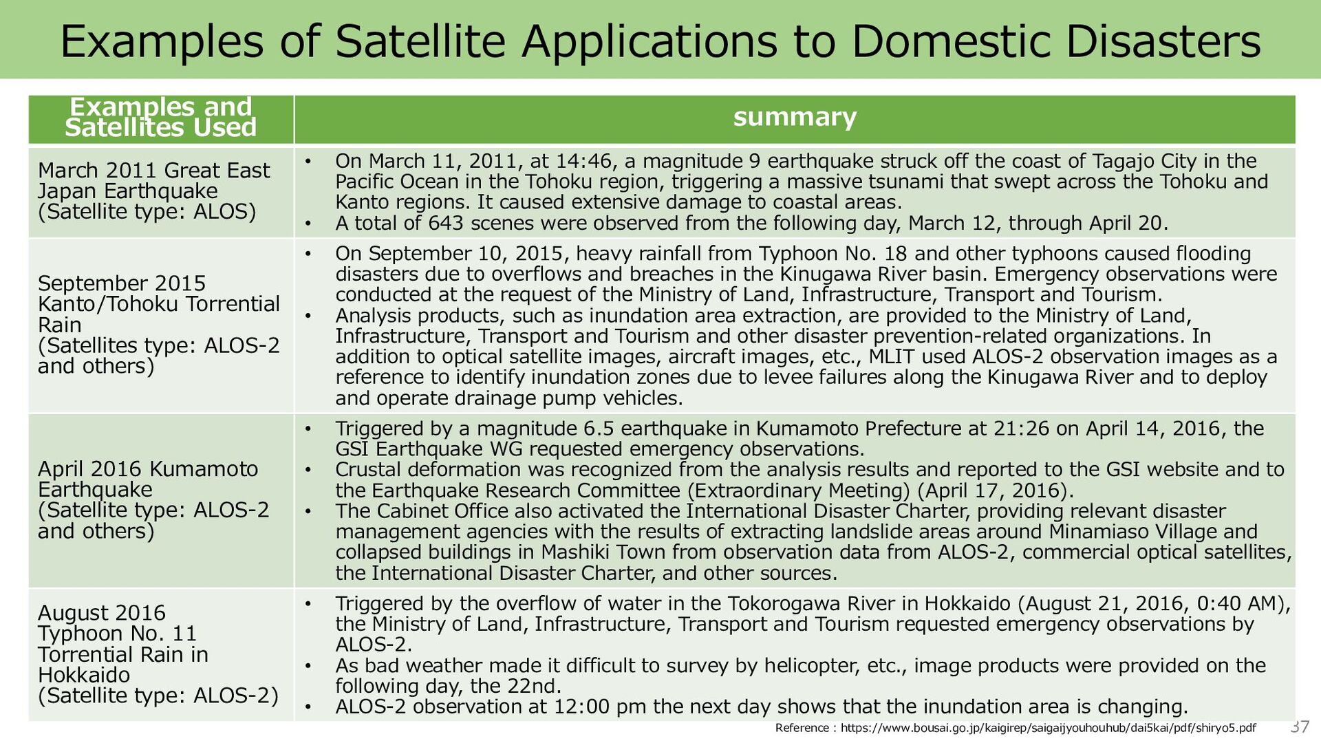
    Satellites Used summary March 2011 Great East Japan Earthquake (Satellite type: ALOS) • On March 11, 2011, at 14:46, a magnitude 9 earthquake struck off the coast of Tagajo City in the Pacific Ocean in the Tohoku region, triggering a massive tsunami that swept across the Tohoku and Kanto regions. It caused extensive damage to coastal areas. • A total of 643 scenes were observed from the following day, March 12, through April 20. September 2015 Kanto/Tohoku Torrential Rain (Satellites type: ALOS-2 and others) • On September 10, 2015, heavy rainfall from Typhoon No. 18 and other typhoons caused flooding disasters due to overflows and breaches in the Kinugawa River basin. Emergency observations were conducted at the request of the Ministry of Land, Infrastructure, Transport and Tourism. • Analysis products, such as inundation area extraction, are provided to the Ministry of Land, Infrastructure, Transport and Tourism and other disaster prevention-related organizations. In addition to optical satellite images, aircraft images, etc., MLIT used ALOS-2 observation images as a reference to identify inundation zones due to levee failures along the Kinugawa River and to deploy and operate drainage pump vehicles. April 2016 Kumamoto Earthquake (Satellite type: ALOS-2 and others) • Triggered by a magnitude 6.5 earthquake in Kumamoto Prefecture at 21:26 on April 14, 2016, the GSI Earthquake WG requested emergency observations. • Crustal deformation was recognized from the analysis results and reported to the GSI website and to the Earthquake Research Committee (Extraordinary Meeting) (April 17, 2016). • The Cabinet Office also activated the International Disaster Charter, providing relevant disaster management agencies with the results of extracting landslide areas around Minamiaso Village and collapsed buildings in Mashiki Town from observation data from ALOS-2, commercial optical satellites, the International Disaster Charter, and other sources. August 2016 Typhoon No. 11 Torrential Rain in Hokkaido (Satellite type: ALOS-2) • Triggered by the overflow of water in the Tokorogawa River in Hokkaido (August 21, 2016, 0:40 AM), the Ministry of Land, Infrastructure, Transport and Tourism requested emergency observations by ALOS-2. • As bad weather made it difficult to survey by helicopter, etc., image products were provided on the following day, the 22nd. • ALOS-2 observation at 12:00 pm the next day shows that the inundation area is changing. Reference:https://www.bousai.go.jp/kaigirep/saigaijyouhouhub/dai5kai/pdf/shiryo5.pdf
  31. Satellite Data Pricing Satellite data prices vary by satellite types

    Number of scenes purchased OR Area New Observati on Option Provided Data Format Option Number of Licenses Satellite Data Price × × × = ◼ Number of images (scenes) covering the area of interest ◼ Recently, some providers allow purchase (subscription) by area of coverage. ◼ Minimum purchase area may be set ◼ Occurs when requesting an observation for a satellite ◼ Not required when purchasing an archive ◼ Depend on the data provided by Geotiff, etc. ◼ Ortho, etc., ◼ Occurs depending on the extent to which satellite data is used ◼ Various forms, such as organizational units ◼ In general, higher resolution tends to be more expensive, while lower resolution satellite imagery is less expensive. Some satellites are free of charge for the acquisition of satellite data itself. ◼ The table on the left shows reference prices for WorldView satellites with high resolution ◼ For WorldView, approximately 167,000 USD is required to purchase the latest data for the entire Tokyo metropolitan area (2,194 km²) Color with 40cm resolution (4band) Price/km^2 (approx.) Archived images that are more than 90 days old from observation 15.98 USD New observations or archived images within 90 days 24.04 USD New observation for a specified period of time 41.97 USD New observation within 14 days 76.19 USD Source:https://sorabatake.jp/466/ 39 ※This is a summary of the main price-related factors, which actually vary from satellite to satellite. ※1 USD = 134.98 JPY
  32. Examples of Private Remote Sensing Satellite Operators 40 entrepreneur country

    Sensor Type summary Highest spatial resolution Number of satellite owned Number of future satellite Maxar United States of America optics It has a number of high-resolution optical satellites. 0.3m 4 aircraft 10 aircraft MDA Canada SAR (C-band) SAR satellites. 1m one aircraft 3 aircraft (Canadian Space Agency) Planet United States of America optics A large constellation of satellites (constellation) is constructed. 3.7m More than 100 aircraft More than 100 aircraft Airbus United States of America Optics SAR(X-band) Constructing high-resolution optical and SAR constellations 0.3m 16 aircraft unknown ICEYE Finland SAR (X-band) Building a constellation of small SAR satellites 0.25m 14 aircraft 18 aircraft (by 2022) Synspective Japan SAR (X-band) A satellite venture aiming to build a SAR satellite constellation. Founded as a derivative of the "ImPACT" program of the Cabinet Office. 1m two aircraft 30 aircraft (by 2026) QPS Research Institute Japan SAR (X-band) Aiming to build a SAR satellite constellation A Kyushu University venture. 0.7m two aircraft 36 aircraft (after 2025) JEOSS (Japan Earth Observation Satellite Service) Japan SAR (X-band) Established by NEC. Operates SAR satellite ASNARO-2. 1m one aircraft unknown Axel Space Japan optics A satellite venture that aims to build an optical satellite constellation. 2.5m Five aircraft 10 aircraft (by 2023) CANON ELECTRONICS Japan Optics Precision machine manufacturer. Currently operating two self-developed optical satellites. 0.9m two aircraft unknown ※Table based on independent research as of July 2022 and accuracy is not guaranteed.
  33. Reference Links link to site URL Japan Aerospace Exploration Agency

    (JAXA) HP https://earth.jaxa.jp/ja/eo-knowledge/ https://earth.jaxa.jp/files/application/disaster/space_a pplication_for_disaster_monitoring.pdf National Aeronautics and Space Administration (NASA) HP https://www.earthdata.nasa.gov/learn/backgrounders/ remote- sensing#:~:text=Remote%20sensing%20is%20the%2 0acquiring,record%20reflected%20or%20emitted%20e nergy. European Space Agency (ESA) HP https://www.esa.int/SPECIALS/Eduspace_EN/SEMF9R3 Z2OF_0.html Sorabatake HP https://sorabatake.jp/ Remote Sensing Technology Center of Japan(RESTEC) HP https://www.restec.or.jp/knowledge/sensing/sensing- 1.html Pasco Corporation HP https://www.pasco.co.jp/recommend/word/word033/ ESRI Japan K.K. HP https://www.esrij.com/gis-guide/imagery/remote- sensing/ 41