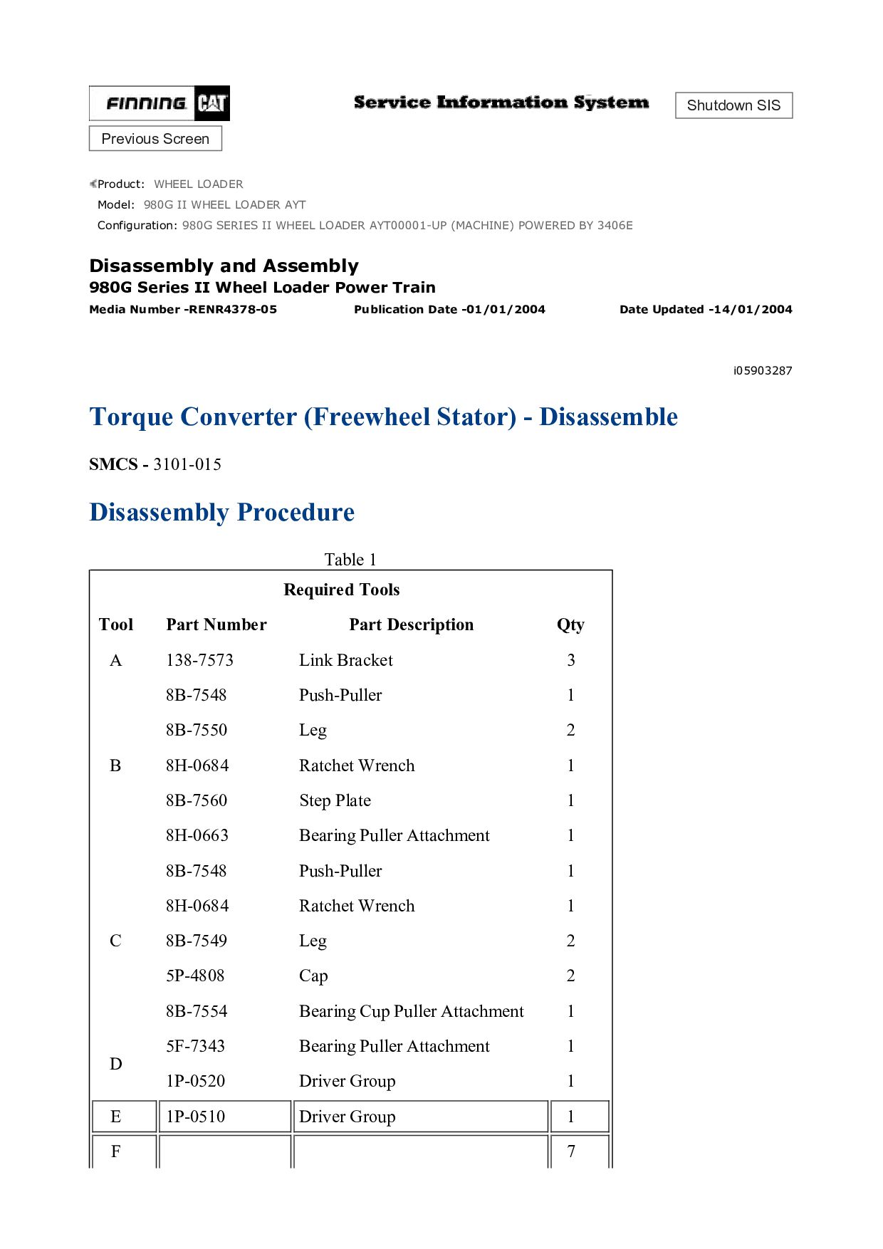
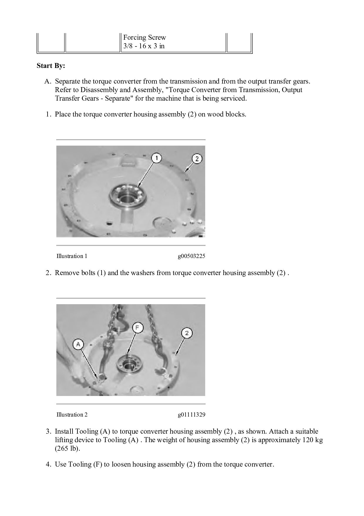
A. Separate the torque converter from the transmission and from the output transfer gears. Refer to Disassembly and Assembly, "Torque Converter from Transmission, Output Transfer Gears - Separate" for the machine that is being serviced. 1. Place the torque converter housing assembly (2) on wood blocks. Illustration 1 g00503225 2. Remove bolts (1) and the washers from torque converter housing assembly (2) . Illustration 2 g01111329 3. Install Tooling (A) to torque converter housing assembly (2) , as shown. Attach a suitable lifting device to Tooling (A) . The weight of housing assembly (2) is approximately 120 kg (265 lb). 4. Use Tooling (F) to loosen housing assembly (2) from the torque converter.
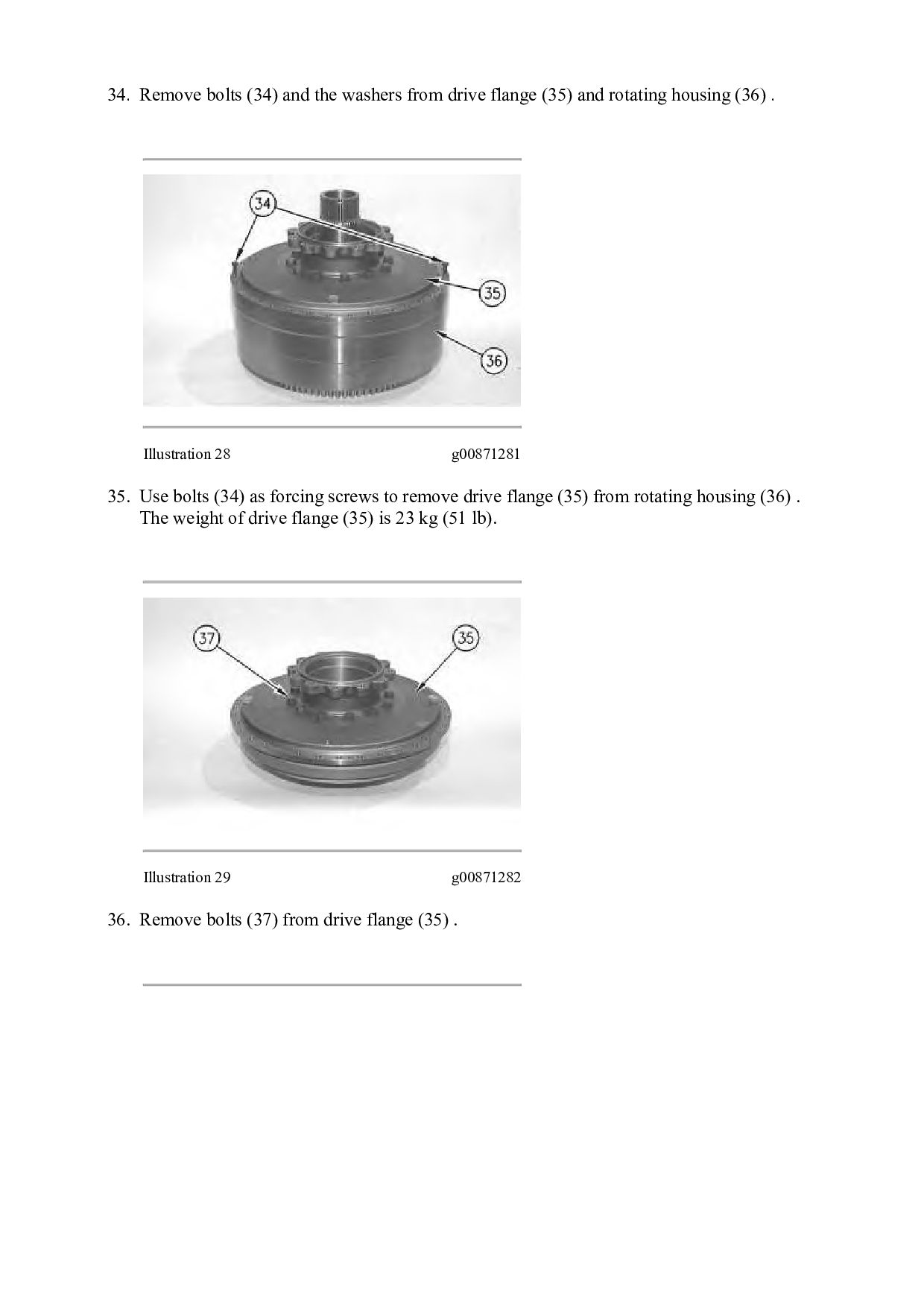
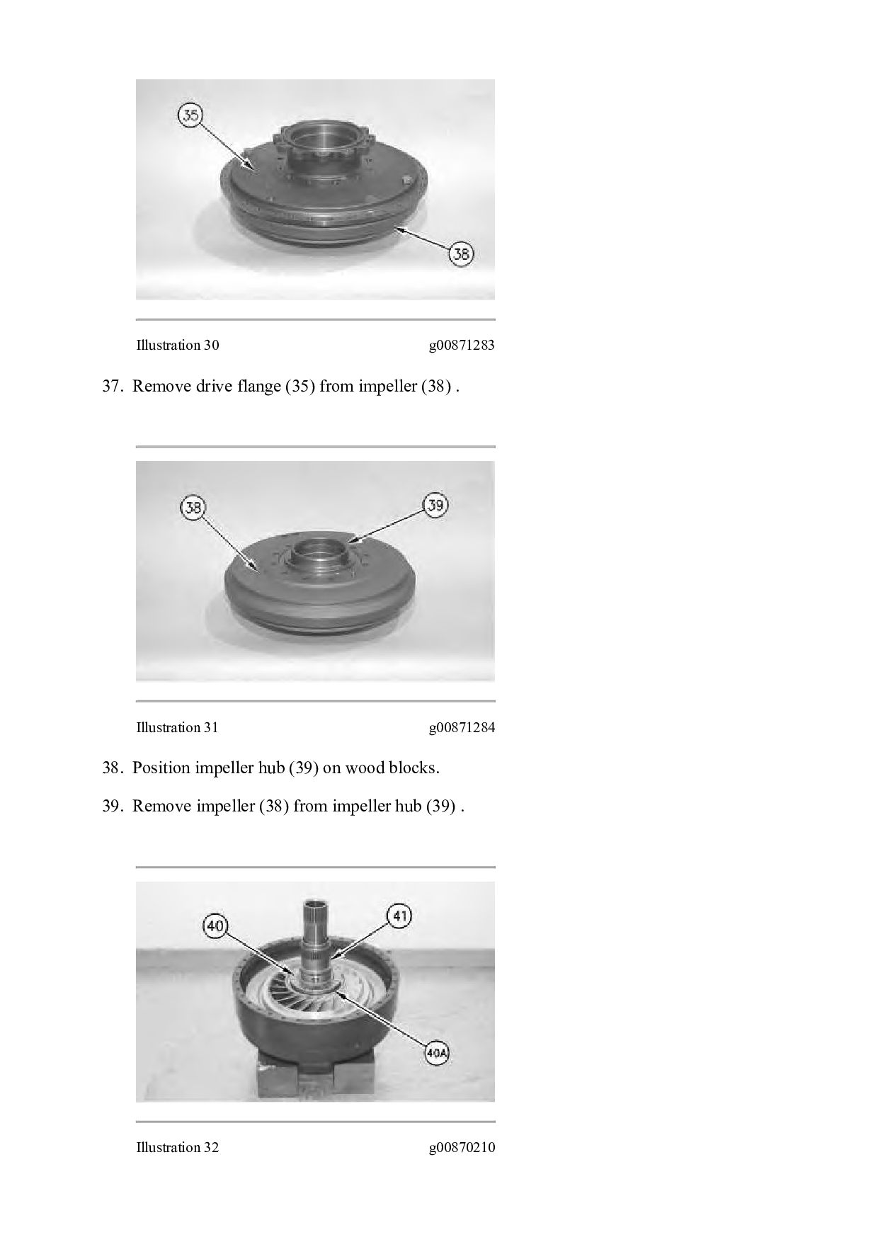
![Please write to us. Our email: [email protected] Please go to](https://files.speakerdeck.com/presentations/b2adb7934b3d450b9ad0941d53c2570a/slide_34.jpg)
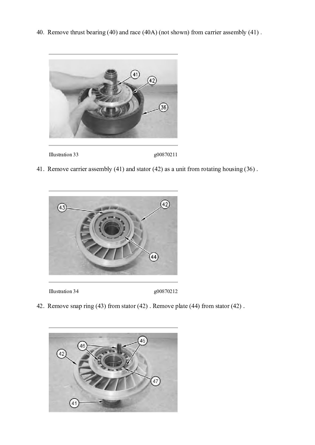