Upgrade to Pro — share decks privately, control downloads, hide ads and more …

Caterpillar_Cat_D6N_TRACK-TYPE_TRACTOR__Prefix_...

dcrfqdcnvk
May 21, 2024
7

 Caterpillar_Cat_D6N_TRACK-TYPE_TRACTOR__Prefix_DJY__Service_Repair_Manual__DJY00001_and_up_.pdf

dcrfqdcnvk

May 21, 2024
Tweet

More Decks by dcrfqdcnvk

Transcript

  1. Shutdown SIS Previous Screen Product: TRACK-TYPE TRACTOR Model: D6N TRACK-TYPE

    TRACTOR DJY Configuration: D6N TRACK-TYPE TRACTOR XL, LGP Differential Steering DJY00001-UP (MACHINE) POWERED BY C6.6 Engine Disassembly and Assembly D6N Track-Type Tractor Power Train Media Number -KENR5137-08 Publication Date -01/07/2018 Date Updated -25/07/2018 i04902472 Steering Planetary and Brake - Disassemble SMCS - 4132-015 Disassembly Procedure Table 1 Required Tools Tool Part Number Part Description Qty A 138-7575 Link Bracket 3 B 1P-0520 Driver Group 1 C - 3/8 × 16 Forcing Screw 3 Start By: a. Remove the right hand final drive, the planetary group, and the brake. Refer to Disassembly and Assembly, "Final Drive, Steering Planetary, and Brake (Right Side) - Remove". Illustration 1 g01234433
  2. 1. Position the final drive, the planetary group, and the

    brake. 2. Remove bolts (1A) (not shown) that hold the planetary group and brake (1) to final drive (2). 3. Attach Tooling (A) and a suitable lifting device (not shown) to the planetary group and brake (1). 4. Install Tooling (C) in the final drive hub. 5. Tighten Tooling (C) evenly in order to separate the planetary group and brake (1) from final drive (2). The weight of the planetary group and brake (1) is approximately 136 kg (300 lb). Illustration 2 g00622109 Personal injury can result from parts and/or covers under spring pressure. Spring force will be released when covers are removed. Be prepared to hold spring loaded covers as the bolts are loosened. 6. Remove bolts (3). 7. Remove ring gear (4) from housing (5).
  3. Illustration 3 g01234571 8. Remove friction discs (6) and the

    brake plates from housing (5). Illustration 4 g00622111 Illustration 5 g00622113 9. Remove bolts (7) and plate (8). Note: Do not allow carrier (10) to fall when the carrier is pressed from housing (5). Note: If a shim pack is present between the plate (9) and planetary carrier (10). Reuse the same shim pack during assembly only if reusing the same planetary carrier (10). If a new planetary carrier (10) is being used the shim pack should be discarded.
  4. 10. Use a suitable press and Tooling (B) to remove

    carrier (10) from housing (5). 11. Remove bearing cone (9) from housing (5). Illustration 6 g00622127 12. Remove ring (14) from planetary carrier (11). 13. Remove bolts (13). 14. Remove slinger (12) from planetary carrier (11). NOTICE The component is destroyed if the component is removed. 15. If necessary, remove bearing cone (15) from planetary carrier (11). Illustration 7 g00996861 16. Use a hammer and a suitable punch to push pin (21) in shaft (20).
  5. https://www.aservicemanualpdf.com/ My Dear Friend! Thank you very much for visiting.

    Full manual if required, please enter the following URL into your browser. https://www.aservicemanualpdf.com/
  6. Illustration 8 g00996857 17. Remove shaft (20), planetary gear (19),

    discs (17), and bearings (18) from planetary carrier (11). 18. Remove pin (21) from shaft (20). 19. Repeat Steps 16 through 18 for the remaining planetary gears. 20. Remove sun gear (16) from planetary carrier (11). Illustration 9 g00622132 Personal injury can result from parts and/or covers under spring pressure. Spring force will be released when covers are removed. Be prepared to hold spring loaded covers as the bolts are loosened. 21. Remove bolts (22) and the washers.
  7. 22. Remove retainer (23) from piston (24). Illustration 10 g00996858

    23. If necessary, remove bearing cups (25) from retainer (23). 24. Remove seal ring (26) from the retainer. Illustration 11 g00622156 25. Remove piston (24) and O-ring seal (27) from the housing. Illustration 12 g00996860 26. Remove seal ring (28) from piston (24).
  8. Illustration 13 g00819345 27. Remove spring (29) and ring (30)

    from housing (5). Copyright 1993 - 2021 Caterpillar Inc. All Rights Reserved. Private Network For SIS Licensees. Thu Oct 21 18:58:36 UTC+0800 2021
  9. Shutdown SIS Previous Screen Product: TRACK-TYPE TRACTOR Model: D6N TRACK-TYPE

    TRACTOR DJY Configuration: D6N TRACK-TYPE TRACTOR XL, LGP Differential Steering DJY00001-UP (MACHINE) POWERED BY C6.6 Engine Disassembly and Assembly D6N Track-Type Tractor Power Train Media Number -KENR5137-08 Publication Date -01/07/2018 Date Updated -25/07/2018 i04902802 Steering Planetary and Brake - Assemble SMCS - 4132-016 Assembly Procedure Table 1 Required Tools Tool Part Number Part Description Qty A 138-7575 Link Bracket 3 D 6V-6640 Sealant 1 Illustration 1 g00819345 Note: Orient the disc spring with the outer edge downward. 1. Install ring (30) and spring (29) in housing (5).
  10. Illustration 2 g00622157 2. Apply clean oil to seal ring

    (28). Note: Orient the seal ring with the lip downward. Refer to Illustration 2. 3. Install seal ring (28) in piston (24). Illustration 3 g00622156 4. Install piston (24) and O-ring seal (27) in the housing. Illustration 4 g00996858 5. Lower the temperature of bearing cups (25). Install bearing cups (25) in retainer (23).
  11. Note: Orient the seal ring with the lip downward. Refer

    to Illustration 4. 6. Apply clean oil to seal ring (26). Install seal ring (26) in retainer (23). Illustration 5 g00622132 7. Install retainer (23) on piston (24). Align the oil passage in retainer (23) with the oil passage and the O-ring seal in the housing. Install bolts (22). Illustration 6 g00996857 8. Install sun gear (16) in planetary carrier (11). 9. Install bearings (18) in planetary gear (19). 10. Install discs (17) and planetary gear (19) in planetary carrier (11). Install shaft (20).
  12. Illustration 7 g00996861 Note: If the rubber in pin (21)

    is damaged, replace pin (21). 11. Align the hole in shaft (20) with the hole in planetary carrier (11) and install pin (21). Install pin (21) until the pin is even with the surface of planetary carrier (11). 12. Repeat Steps 9 through 11 for the remaining planetary gears. Illustration 8 g00622127 Note: If bearing cone (15) was removed from planetary carrier (11), a new bearing must be installed. 13. Raise the temperature of bearing cone (15). Install the bearing cone on planetary carrier (11). 14. Apply Tooling (D) to the flange of slinger (12). 15. Install slinger (12) on planetary carrier (11). Install bolts (13). Tighten bolts (13) to a torque of 50 ± 10 N·m (37 ± 7 lb ft). 16. Install ring (14) in planetary carrier (11).
  13. Illustration 9 g00622176 17. Position housing (5) on planetary carrier

    (11). 18. Raise the temperature of bearing cone (9). Install bearing cone (9) on planetary carrier (11). Illustration 10 g00818972 19. Position plate (8) on the planetary carrier. Note: Install shim pack between plate (8) and planetary carrier (11), only if there was a shim pack originally installed in the differential group and if the same planetary carrier (11) is being reused. Shim pack thickness should be 0.31 mm (0.012nch). 20. Install bolts (7) .
  14. Illustration 11 g00622110 21. Install friction discs (6) and brake

    plates. Alternate the friction discs and the brake plates. Illustration 12 g00622109 22. Position ring gear (4) on housing (5). 23. Install bolts (3). Tighten bolts (3) to a torque of 135 ± 20 N·m (100 ± 15 lb ft). Illustration 13 g01234433 24. Use Tooling (A) and a suitable lifting device (not shown) in order to position the planetary group and brake (1) on final drive (2). The weight of the planetary group and brake (1) is approximately 135 kg (300 lb). 25. Install bolts (1A) that hold the planetary group and brake (1) on the final drive. End By: a. Install the right hand final drive, the planetary group, and the brake. Refer to Disassembly and Assembly, "Final Drive, Steering Planetary, and Brake (Right Side) - Install". Copyright 1993 - 2021 Caterpillar Inc. All Rights Reserved. Private Network For SIS Licensees. Thu Oct 21 18:59:32 UTC+0800 2021
  15. Shutdown SIS Previous Screen Product: TRACK-TYPE TRACTOR Model: D6N TRACK-TYPE

    TRACTOR DJY Configuration: D6N TRACK-TYPE TRACTOR XL, LGP Differential Steering DJY00001-UP (MACHINE) POWERED BY C6.6 Engine Disassembly and Assembly D6N Track-Type Tractor Power Train Media Number -KENR5137-08 Publication Date -01/07/2018 Date Updated -25/07/2018 i03630400 Final Drive, Steering Planetary, and Brake (Right Side) - Install SMCS - 4050-012-RI; 4132-012-RI Installation Procedure Table 1 Required Tools Tool Part Number Part Description Qty A 8T-3207 Lifting Bracket 1 5P-8622 Shackle 1 9S-9076 Spacer 1 7X-2557 Bolt 2 Note: Cleanliness is an important factor. Before you begin the installation procedure, the exterior of the components should be thoroughly cleaned. This will help to prevent dirt from entering the internal mechanism.
  16. Illustration 1 g01237378 1. Install O-ring seals (7) to the

    final drive, the steering planetary, and brake (3) . Illustration 2 g00956633 2. Adjust bracket (1) until Dimension (X) is equal to 55 mm (2.0 inch). Illustration 3 g01237459
  17. 3. Attach Tooling (A) and a suitable lifting device to

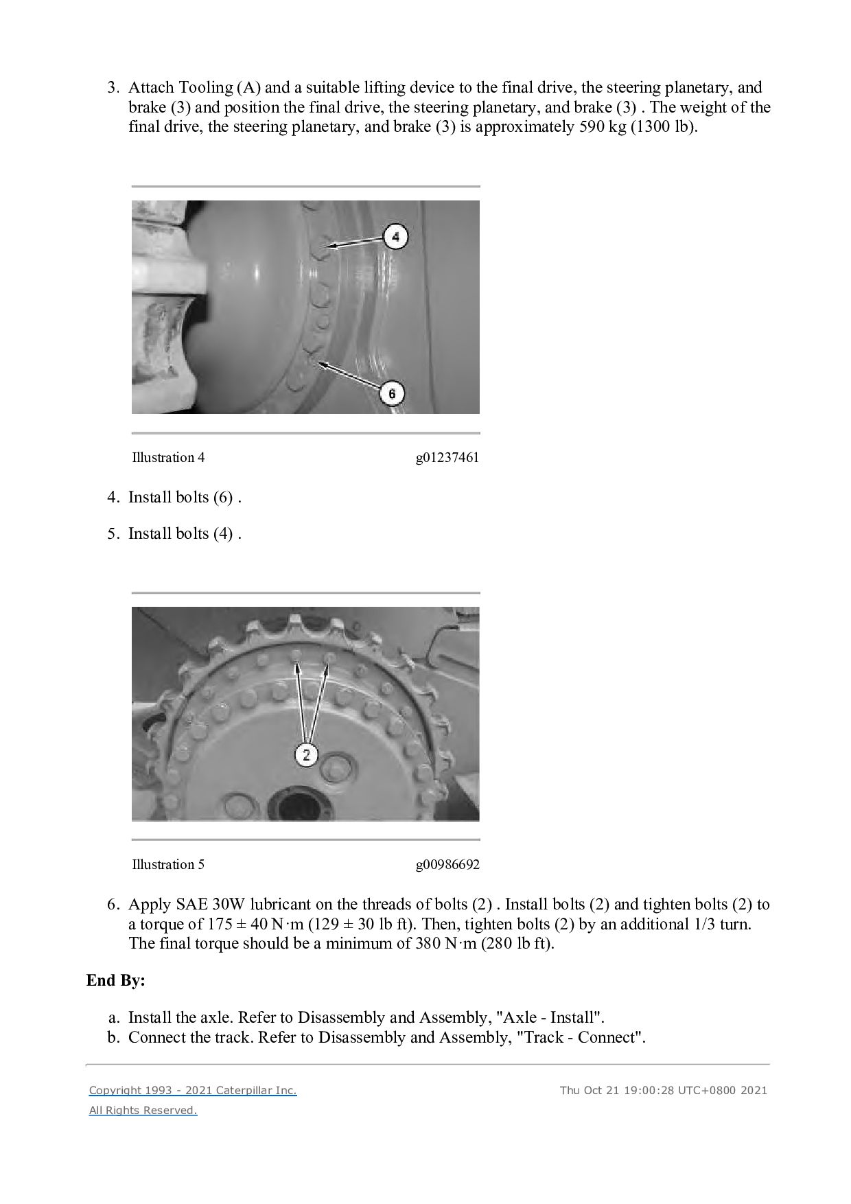
    the final drive, the steering planetary, and brake (3) and position the final drive, the steering planetary, and brake (3) . The weight of the final drive, the steering planetary, and brake (3) is approximately 590 kg (1300 lb). Illustration 4 g01237461 4. Install bolts (6) . 5. Install bolts (4) . Illustration 5 g00986692 6. Apply SAE 30W lubricant on the threads of bolts (2) . Install bolts (2) and tighten bolts (2) to a torque of 175 ± 40 N·m (129 ± 30 lb ft). Then, tighten bolts (2) by an additional 1/3 turn. The final torque should be a minimum of 380 N·m (280 lb ft). End By: a. Install the axle. Refer to Disassembly and Assembly, "Axle - Install". b. Connect the track. Refer to Disassembly and Assembly, "Track - Connect". Copyright 1993 - 2021 Caterpillar Inc. All Rights Reserved. Thu Oct 21 19:00:28 UTC+0800 2021
  18. Shutdown SIS Previous Screen Product: TRACK-TYPE TRACTOR Model: D6N TRACK-TYPE

    TRACTOR DJY Configuration: D6N TRACK-TYPE TRACTOR XL, LGP Differential Steering DJY00001-UP (MACHINE) POWERED BY C6.6 Engine Disassembly and Assembly D6N Track-Type Tractor Power Train Media Number -KENR5137-08 Publication Date -01/07/2018 Date Updated -25/07/2018 i02477788 Final Drive - Remove SMCS - 4050-011 Removal Procedure Table 1 Required Tools Tool Part Number Part Description Qty A 8T-3207 Lifting Bracket 1 5P-8622 Shackle 1 9S-9076 Spacer 1 7X-2557 Bolt 2 Start By: a. Separate the track. Refer to Disassembly and Assembly, "Track - Seperate". b. Remove the axle. Refer to Disassembly and Assembly, "Axle - Remove". NOTICE Care must be taken to ensure that fluids are contained during performance of inspection, maintenance, testing, adjusting, and repair of the product. Be prepared to collect the fluid with suitable containers before opening any compartment or disassembling any component containing fluids. Refer to Special Publication, NENG2500, "Dealer Service Tool Catalog" for tools and supplies suitable to collect and contain fluids on Cat products.
  19. Dispose of all fluids according to local regulations and mandates.

    Note: Cleanliness is an important factor. Before you begin the removal procedure, the exterior of the components should be thoroughly cleaned. This will help to prevent dirt from entering the internal mechanism. 1. Drain the oil from the final drive. Refer to Operation and Maintenance Manual, "Final Drive Oil - Change". Illustration 1 g00956633 2. Adjust bracket (1) until Dimension (X) is equal to 80 mm (3.0 inch). Illustration 2 g00986692 3. Remove bolts (2).
  20. Illustration 3 g01237341 Illustration 4 g01237514 4. Attach Tooling (A)

    and a suitable lifting device to final drive (3). 5. Remove bolts (4) and bolts (5). Note: Do not remove bolts (6). 6. Remove final drive (3). The weight of final drive (3) is approximately 408 kg (900 lb). Copyright 1993 - 2021 Caterpillar Inc. All Rights Reserved. Private Network For SIS Licensees. Thu Oct 21 19:01:23 UTC+0800 2021
  21. Shutdown SIS Previous Screen Product: TRACK-TYPE TRACTOR Model: D6N TRACK-TYPE

    TRACTOR DJY Configuration: D6N TRACK-TYPE TRACTOR XL, LGP Differential Steering DJY00001-UP (MACHINE) POWERED BY C6.6 Engine Disassembly and Assembly D6N Track-Type Tractor Power Train Media Number -KENR5137-08 Publication Date -01/07/2018 Date Updated -25/07/2018 i06691352 Final Drive - Disassemble SMCS - 4050-015 Disassembly Procedure Table 1 Required Tools Tool Part Number Part Description Qty A 439-3938 Link Bracket 3 B 1P-0074 Slide Hammer Puller Gp 1 C FT-1934 Puller Beam 1 - (16 mm x 190.5 mm) Bolt 4 5P-8247 Hard Washer 4 6V-3170 Double Acting Cylinder 1 9U-6600 Hand Hydraulic Pump 1 1P-0521 Driver Group 1 D 439-3940 Bracket As 2 Start By: a. Remove the final drive.
  22. Illustration 1 g01234745 1. Attach Tooling (A) and a suitable

    lifting device to carrier (1). The weight of carrier (1) is approximately 50 kg (110 lb). 2. Remove bolts (2) and carrier (1) from sprocket hub (3). Position carrier (1) onto suitable cribbing. Illustration 2 g01234760 3. Remove bolt (4), the washer, the retainer, and the O-ring seal from carrier (1). 4. Use a suitable press to remove shaft (5) from carrier (1). 5. Repeat Steps 3 and 4 for the remaining shafts.
  23. Illustration 3 g06077476 6. Remove planetary gear (8) from carrier

    (1). 7. Remove bearing cones (6) and (9) from planetary gear (8). 8. Remove bearing cups (7) from planetary gear (8). 9. Repeat Steps 6 through 8 for the remaining planetary gears.
  24. Illustration 4 g00988981 10. Remove bolts (10) and retainer (11).

    11. Remove ring gear hub (12) and ring gear (13). Illustration 5 g00988984 12. Remove ring (14) and ring gear hub (12) from ring gear (13). Illustration 6 g00988985 13. Use Tooling (B) to remove bushing (15) and lip-type seal (16) (not shown).
  25. Illustration 7 g00988979 14. Raise the temperature of bearing cone

    (17). 15. Use Tooling (C) to remove bearing cone (17) from the spindle. Note: Do not lift the sprocket hub so that the sprocket hub contacts the fittings that are on the hydraulic cylinder. Damage to the fittings could occur. 16. Remove Tooling (C). Illustration 8 g01235181 17. Attach Tooling (D) and a suitable lifting device to sprocket hub (3). The weight of sprocket hub (3) is approximately 135 kg (298 lb). Remove sprocket hub (3) from the spindle.
  26. Illustration 9 g01235238 18. Remove bearing cups (18) and (19)

    from sprocket hub (3). 19. Remove Duo-cone seal (20) from sprocket hub (3). Illustration 10 g01235241 20. Remove Duo-cone seal (22) from spindle (23). 21. Remove bearing cone (21) from spindle (23). Copyright 1993 - 2021 Caterpillar Inc. All Rights Reserved. Private Network For SIS Licensees. Thu Oct 21 19:02:19 UTC+0800 2021
  27. Shutdown SIS Previous Screen Product: TRACK-TYPE TRACTOR Model: D6N TRACK-TYPE

    TRACTOR DJY Configuration: D6N TRACK-TYPE TRACTOR XL, LGP Differential Steering DJY00001-UP (MACHINE) POWERED BY C6.6 Engine Disassembly and Assembly D6N Track-Type Tractor Power Train Media Number -KENR5137-08 Publication Date -01/07/2018 Date Updated -25/07/2018 i03902166 Final Drive - Assemble SMCS - 4050-016 Assembly Procedure Table 1 Required Tools Tool Part Number Part Description Qty A 138-7573 Link Bracket 3 D 138-7575 Link Bracket 2 E 1P-0520 Driver Gp 1 F 169-0503 Installation Kit 1 8M-9395 Seal Installer 1 G 1U-7234 Feeler Gauge 1
  28. Illustration 1 g01235241 1. Raise the temperature of bearing cone

    (21). Install bearing cone (21) onto spindle (23). 2. Use Tooling (F) (not shown) in order to install Duo-cone seal (22). Refer to Disassembly and Assembly, "Duo-Cone Conventional Seals - Install". Illustration 2 g01235238 3. Lower the temperature of bearing cups (19) and (18). 4. Install bearing cups (19) and (18) in hub (3). 5. Use Tooling (F) (not shown) in order to install Duo-cone seal (20) in hub (3). Refer to Disassembly and Assembly, "Duo-Cone Conventional Seals - Install".
  29. Illustration 3 g01235181 6. Install Tooling (D) and a suitable

    lifting device to hub (3). Install hub (3) onto the spindle. The weight of hub (3) is approximately 135 kg (298 lb). Illustration 4 g00990323 7. Install lip seal (16) and sleeve bearing (15).
  30. Thank you very much for your reading. Please Click Here.

    Then Get COMPLETE MANUAL. NO WAITING NOTE: If there is no response to click on the link above, please download the PDF document first and then click on it.
  31. Illustration 6 g02145273 9. Raise the temperature of bearing cone

    (17). Install bearing cone (17) on the spindle. 10. Install hub (12) and gear (13) as an assembly. 11. Install retainer (11) and bolts (10). Tighten all bolts (10) in a star pattern. Tighten bolts (10) to a torque of 120 ± 20 N·m (89 ± 15 lb ft). Continually rotate hub (12) in order to properly seat bearing cone (17). Tighten bolts (10) to a torque of 120 ± 20 N·m (89 ± 15 lb ft) in order to ensure the proper torque. 12. Use Tooling (G) (not shown) in order to verify that the spindle is touching the retainer. 13. If necessary, repeat Step 11 and Step 12 in order to verify that bearing cone (17) is seated properly.
  32. Illustration 7 g01234812 14. Lower the temperature of bearing cups

    (7). Install bearing cups (7) into gear (8). 15. Position bearing cones (6) and (9) into gear (8). 16. Position gear (8) into carrier (1). Illustration 8 g01235164 17. Lower the temperature of shaft (5). Use a suitable press in order to install shaft (5). Install shaft (5) until the end of the shaft is flush with the outer surface of carrier (1). 18. Install bolt (4) and the plate to carrier (1). 19. Verify that there is metal to metal contact between plates (4) and the shafts. 20. Repeat Steps 17 through 19 for the remaining shafts.
  33. Illustration 9 g01234745 21. Attach Tooling (A) to carrier (1).

    Position carrier (1) into hub (3). The weight of carrier (1) is approximately 41 kg (90 lb). 22. Install bolts (2). 23. Remove Tooling (A). End By: a. Install the final drive. Refer to Disassembly and Assembly, "Final Drive - Install". Copyright 1993 - 2021 Caterpillar Inc. All Rights Reserved. Private Network For SIS Licensees. Thu Oct 21 19:03:15 UTC+0800 2021
  34. https://www.aservicemanualpdf.com/ My Dear Friend! Thank you very much for visiting.

    Full manual if required, please enter the following URL into your browser. https://www.aservicemanualpdf.com/