Upgrade to Pro — share decks privately, control downloads, hide ads and more …

Caterpillar_Cat_980F_II_WHEEL_LOADER__Prefix_4RN__Service_Repair_Manual__4RN00001_and_up_.pdf

dcfv
May 20, 2024
4

 Caterpillar_Cat_980F_II_WHEEL_LOADER__Prefix_4RN__Service_Repair_Manual__4RN00001_and_up_.pdf

dcfv

May 20, 2024
Tweet

More Decks by dcfv

Transcript

  1. Shutdown SIS Previous Screen Product: WHEEL LOADER Model: 980F II

    WHEEL LOADER 4RN Configuration: 980F II WHEEL LOADER 4RN00001-UP (MACHINE) POWERED BY 3406C DI ENGINE Disassembly and Assembly 3406C DIESEL ENGINES FOR CATERPILLAR BUILT MACHINES Media Number -SENR6409-02 Publication Date -01/07/2006 Date Updated -19/05/2015 SENR64090009 Fuel Injection Pumps SMCS - 1251-011; 1251-012; 1251-017 Remove Fuel Injection Pumps Start By: a. remove fuel injection lines 1. Remove the plug, and move the race until Tool (A) can be installed to hold the rack in the center position. The rack must be in the center position to remove the fuel injection pumps. To prevent possible personal injury carefully follow the steps below.
  2. 2. Put Tool (B), except for the 8T5287 Wrench, in

    position on the fuel pump housing as shown. Lower the handle to center the adjusting screw with the fuel line seat. With the handle down in the locked position, the adjusting screw must just be in contact with fuel line seat (1). If force is needed to lower the handle or there is a gap, remove the tooling, and make an adjustment to the screw. 3. Loosen bushing (2) 1/4 of a turn. 4. Put Tool (B) in position on the pump housing with the handle down in the locked position as shown. 5. Remove bushing (2) from the pump housing. 6. Carefully and slowly lift the handle to release the spring force. Remove the tooling. 7. Install Tool (C) on fuel pump (4) as shown. 8. Remove seal (3) and fuel pump (4) from the fuel pump housing. 9. Remove spacers (5) from the pump housing. NOTE: There must be a pump installed on either side of the pump to be removed to install Tool (B). If there is no pump, take a pump already removed, and remove the spring so there will be no spring force, and install it in the pump housing. See Install Fuel Pump. NOTE: Spacers (5) are the same thickness for each fuel injection pump so they can be mixed. The fuel injection pump plungers and barrels are sets and cannot be mixed. Install Fuel Injection Pumps
  3. 1. Install spacers (5) in the fuel pump housing. 2.

    Move the rack until Tool (A) can be installed to hold the rack in the center position. The rack must be in the center position to install the fuel injection pumps. 3. Install a fuel pump without its spring so that Tool (B) can be installed. See Step 5 for correct fuel pump installation. 4. Install Tool (C) on the bonnet of the fuel pump as shown. 5. Install the fuel pump in the pump housing with the saw cut (slot) (9) in the gear in alignment with small pin (6) in the lifter assembly and groove (8) in the barrel in alignment with large pin (7) in the pump housing.
  4. 6. Install the seal and bushing (2) on the fuel

    pump. 7. Put Tool (B) in position on the fuel pump housing as shown. 8. Lower the handle slowly and carefully. If the fuel pump is not installed correctly, the handle will not go all the way down. Do not try to use force on it. Remove and install the tooling and the fuel pump again. 9. Make sure the seal is in its correct position, and start to tighten bushing (2). Remove the tooling, and tighten the bushing to a torque of 260 ± 15 N·m (190 ± 10 lb ft). Back off 180 degrees and tighten the bushing again to a torque of 260 ± 15 N·m (190 ± 10 lb ft). Typical Example 10. After each fuel pump has been installed, follow the steps below to check total race travel to make sure each pump has been installed correctly. a. Install Tool (D) on the fuel pump housing as shown and zero the dial indicator. b. Remove Tool (A) from the fuel pump housing. c. Move rack (10) in and out of the fuel pump housing to measure rack travel. Rack travel is approximately 9.62 mm (.379 in) in the plus (full fuel) direction and 10.40 mm (.410 in) in the minus (shutoff) direction. If this measurement is not obtained, center the rack, install Tool (A), and remove and install the fuel pump again. NOTE: One tooth off and rack travel is approximately 6.35 to 6.82 mm (.250 to .269 in) in the plus direction and 7.02 to 7.05 mm (.276 to .278 in) in the minus direction. End By: a. install fuel injection lines Disassemble & Assemble Fuel Injection Pumps See SMHS8378 for the correct tool usage. Start By:
  5. a. remove fuel injection pumps NOTICE Be careful when the

    injection pumps are disassembled. Do not damage the surfaces of the plungers, barrels and bonnets. Any scratches will cause leakage inside the fuel injection pump. The plunger and barrel for each pump are made as a set. Do not put the plunger of one pump in the barrel of another pump. If one part has wear, install a complete new pump assembly. Be careful when the plunger is put into the bore of the barrel. NOTE: Do not remove the gear from the plunger. The gear and plunger are assembled and adjusted at the factory. 1. Pull plunger (4) and washer (3) out of barrel (1) and spring (2). 2. Remove spring (2) from barrel (1). 3. Use the following procedure to put the fuel pump in position on Tool (A): a. Select the correct turret position. b. Place a barrel assembly into the turret.
  6. https://www.aservicemanualpdf.com/ My Dear Friend! Thank you very much for visiting.

    Full manual if required, please enter the following URL into your browser. https://www.aservicemanualpdf.com/
  7. c. Loosen the nut on the clamp. d. Adjust clamp

    end (6) until the bonnet is almost touching the barrel when the clamp handle is in the locked position. e. Tighten the nut on the clamp. 4. Use Tool (B) to expand ring (5), and carefully lift it off the fuel pump. 5. Slowly release the clamp handle of Tool (A), and remove the lockring. 6. Remove bonnet (7), spring (8) and valve (9) from barrel (1). NOTE: The following steps are for assembly of the fuel injection pumps. NOTICE Put clean fuel on all parts during assembly. 7. Put spring (8) and valve (9) in bonnet (7). 8. Put bonnet (7) barrel (1) and ring (5) in position on Tool (A). 9. Put the barrel assembly in position on Tool (A). Lower the handle on Tool group (A) to hold the fuel pump together. 10. Use Tool (B), and lower ring (5) on to the barrel and the bonnet to hold them together. 11. Remove the barrel assembly from Tool (B). 12. Install spring (2) on barrel (1). 13. Install washer (3) on plunger (4). Make sure the spring seat on the washer is away from the gear on the plunger. 14. Install plunger (4) in barrel (1). Make sure spring (2) is engaged in the spring seat on washer (3). End By: a. install fuel injection pumps Copyright 1993 - 2021 Caterpillar Inc. All Rights Reserved. Private Network For SIS Licensees. Fri Dec 24 14:56:01 UTC+0800 2021
  8. Shutdown SIS Previous Screen Product: WHEEL LOADER Model: 980F II

    WHEEL LOADER 4RN Configuration: 980F II WHEEL LOADER 4RN00001-UP (MACHINE) POWERED BY 3406C DI ENGINE Disassembly and Assembly 3406C DIESEL ENGINES FOR CATERPILLAR BUILT MACHINES Media Number -SENR6409-02 Publication Date -01/07/2006 Date Updated -19/05/2015 SENR64090010 Fuel Injection Pump Housing SMCS - 1253-015; 1253-016 Disassemble Fuel Injection Pump Housing Start By: a. disassemble governor b. remove fuel injection pumps 1. Remove the six lifters from the fuel pump housing. 2. Remove rack (1) and camshaft (2) from the fuel pump housing. If necessary, use a soft hammer to push the camshaft out the governor end.
  9. 3. Use Tool (A) and remove the three camshaft bearings

    from the fuel pump housing. 4. Remove rack bearing (4) and the other rack bearing from the fuel pump housing. 5. Remove dowel (3) from the fuel pump housing. 6. Remove bolts (6), cover (5) and the gasket from the fuel pump housing. Assemble Fuel Injection Pump Housing
  10. 1. Install gasket (7) and cover (5) on the side

    of the fuel pump housing. 2. Use Tool (B) and install the D shaped rack bearing into the governor and fuel pump drive side of the fuel pump housing 87.0 ± 0.5 mm (3.42 ± .02 in) from outside surface (X). 3. The inside flat diameter after assembly must be 11.178 ± 0.050 mm (.440 ± .002 in) and the inside large diameter must be 12.767 ± 0.058 mm (.503 ± .002 in). 4. Install dowel (3) in the fuel pump housing 6.0 ± 0.5 (.24 ± .02 in) above the outside surface. 5. Use Tool (C) and install the rack bearing into the fuel pump housing 7.16 ± 0.13 mm (.282 ± .005 in) below the surface of the pump housing. 6. The inside diameter of the bearing after assembly must be 12.746 ± 0.045 (.502 ± .002 in). 7. Use Tool (A) and install the three camshaft bearings in the fuel pump housing with the oil holes in the bearings 30 ± 3 degrees from the horizontal center line toward the plugged holes in the fuel pump housing.
  11. 8. The inside diameter of all three bearings after assembly

    must be 68.399 ± 0.038 mm (2.6905 ± .0015 in). 9. Make sure bearing (8) on the governor and fuel pump drive is installed 1.0 ± 0.5 mm (.04 ± .02 in) below surface (Y). 10. Make sure middle bearing (9) is 218 ± 0.3 mm (8.6 ± .01 in) below surface (Y). 11. Make sure bearing (10) governor side is 1.00 ± 0.25 mm (.040 ± .010 in) below the outside surface. 12. Remove the plugs from the side of the fuel pump housing. The oil holes in the bearings must in alignment with holes (11) in the fuel pump housing. If the bearings are not in alignment, remove them and install again. 13. Make an alignment of rack (1) and install it in the fuel pump housing. 14. Install the six lifters in the fuel pump housing. Make sure the pins in the lifter are on the same side as the dowels in the fuel pump housing. End By: a. install fuel injection pumps b. assemble governor Fri Dec 24 14:56:48 UTC+0800 2021
  12. Shutdown SIS Previous Screen Product: WHEEL LOADER Model: 980F II

    WHEEL LOADER 4RN Configuration: 980F II WHEEL LOADER 4RN00001-UP (MACHINE) POWERED BY 3406C DI ENGINE Disassembly and Assembly 3406C DIESEL ENGINES FOR CATERPILLAR BUILT MACHINES Media Number -SENR6409-02 Publication Date -01/07/2006 Date Updated -19/05/2015 SENR64090011 Fuel Ratio Control SMCS - 1278-010; 1278-017 Remove & Install Fuel Ration Control 1. Disconnect air line (1) from the fuel ratio control. 2. Remove wire seal (4) from the bolts. 3. Remove bolts (3) that hold fuel ratio control (2). 4. Remove the fuel ratio control by pulling down and out from the collar. NOTE: The following steps are for the installation of the fuel ratio control. 5. Put fuel ratio control (2) in position on the governor. Make sure the valve head of the fuel ratio control is connected in the groove of the collar. 6. Install bolts (3) that hold the fuel ratio control to the governor. Connect air line (1) to the fuel ratio control.
  13. 7. To make an adjustment to the fuel ratio control,

    see the topic "Governor Adjustment For The Air Fuel Ratio Control" in, Testing & Adjusting Manual SENR6471. 8. Install wire seal (4) on the bolts with Tool (A). Disassemble & Assemble Fuel Ratio Control Start By: a. remove fuel ratio control 1. Put Tool (A) in a vise so that the station being used is not over the vise jaw. Place the fuel ratio control over the pins in Tool (A). Remove bolts (3) and remove cover (26) and gasket (24). NOTICE There is spring force behind cover (7). Hold cover (7) in position, and slowly remove the bolts that hold it to release the spring force.
  14. 2. Remove bolts (6). Remove cover (7) from housing (10).

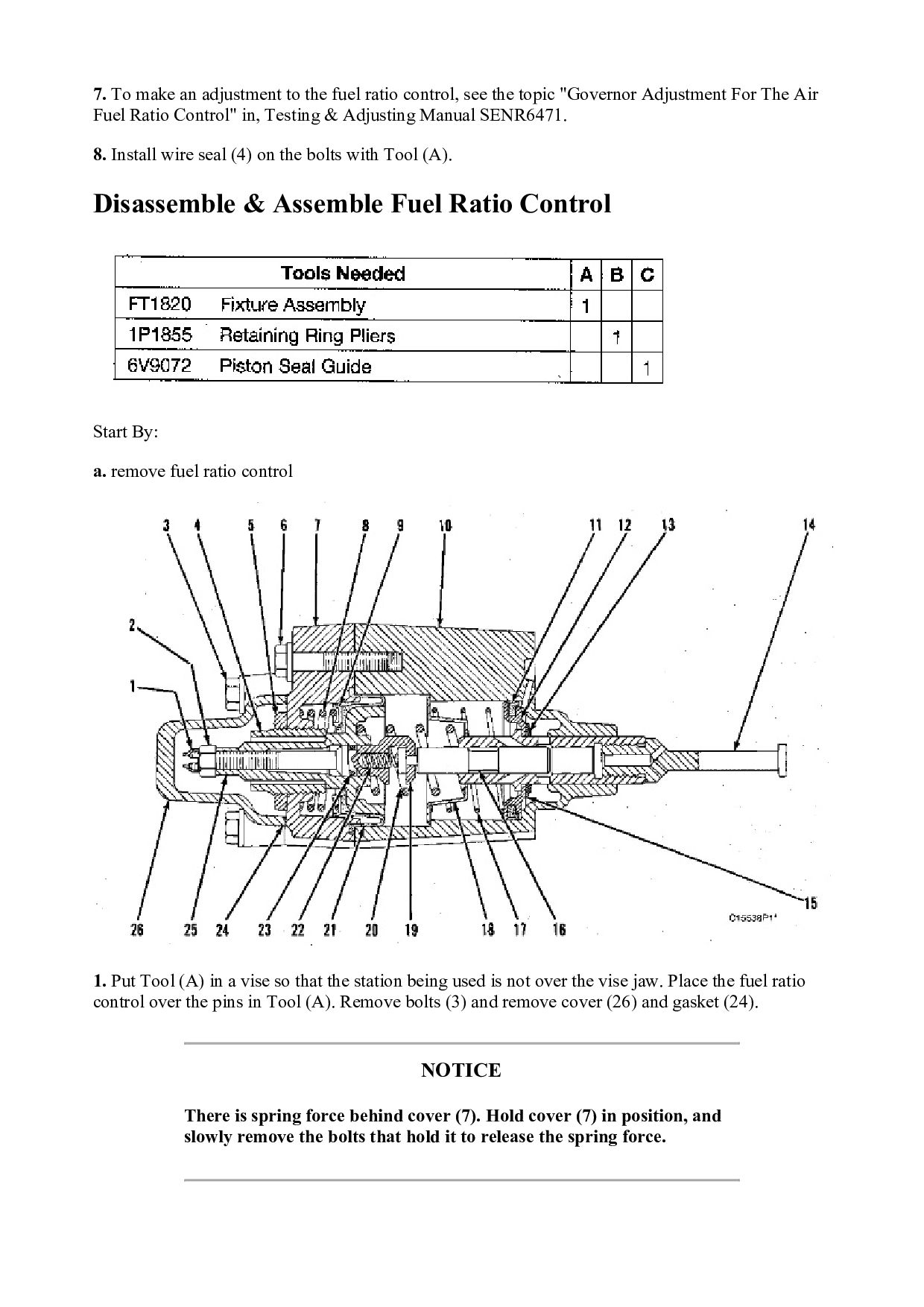
    3. Remove nut (5) and stop (4) from cover (7). 4. Remove spring (8), washer (9) and diaphragm (21) from retainer (25). Remove retainer (25) from housing (10). 5. Remove tube (1) from the end of extension (19). Remove nut (2) from extension (19) and remove the extension from retainer (25). Remove valve (16), spring (22) and O-ring seal (23) from the extension. 6. Remove spring (20), retainer (18) and spring (17) from housing (10). 7. Remove piston (12) and valve assembly (14) from the housing. 8. Use Tool (B) and remove snap ring (13) and washer (15) from the valve assembly. Remove piston (12) from the valve assembly. 9. Remove seal (11) from piston (12). 10. If necessary, remove the stem portion from valve assembly (14). 11. Clean and inspect all parts. Make a replacement of all parts that are worn and damaged. NOTE: The following steps are for the assembly of the fuel ratio control. 12. If removed during disassembly, assemble the stem portion of valve assembly (14) on the valve using 9S3265 Retaining Compound. 13. Lubricate seal (11) lightly with the lubricant being sealed. Put seal (11) on piston (12) and put piston (12) on valve assembly (14). 14. Put washer (15) in position on the valve assembly and use Tool (B) to install snap ring (13) on the valve assembly. 15. Place housing (10) on Tool (A), and put Tool (C) into the bore of the housing. Lubricate Tool (C) with clean engine oil. 16. Push piston (12) into position with a smooth swift motion. Remove Tool (C) from the housing. Place spring (17), retainer (18) and spring (20) in housing (10). 17. Put O-ring seal (23) on extension (19). Put spring (22) and valve (16) in position on the extension. 18. Lubricate the bore of retainer (25) and O-ring seal (23) with clean engine oil. Install extension (19) in retainer (25). Install nut (2) on extension (19). 19. Place tube (1) on the end of extension (19). Heat the tube to a temperature of 149°C (300°F) or until the tube shrinks. 20. Put diaphragm (21), washer (9) and spring (8) in position on retainer (25). Install retainer (25) in housing (10). 21. Install stop (4) and nut (5) in cover (7). Hold retainer (25) in position and install cover (7) on housing (10). Install bolts (6) that hold the cover and tighten them to a torque of 9 ± 3 N·m (7 ± 2 lb ft).
  15. 22. Make a replacement of gasket (24) and install the

    gasket and cover (26) with bolts (3). End By: a. install fuel ratio control Copyright 1993 - 2021 Caterpillar Inc. All Rights Reserved. Private Network For SIS Licensees. Fri Dec 24 14:57:36 UTC+0800 2021
  16. Shutdown SIS Previous Screen Product: WHEEL LOADER Model: 980F II

    WHEEL LOADER 4RN Configuration: 980F II WHEEL LOADER 4RN00001-UP (MACHINE) POWERED BY 3406C DI ENGINE Disassembly and Assembly 3406C DIESEL ENGINES FOR CATERPILLAR BUILT MACHINES Media Number -SENR6409-02 Publication Date -01/07/2006 Date Updated -19/05/2015 SENR64090012 Fuel Injection Lines SMCS - 1252-010 Remove & Install Fuel Injection Lines If fuel line clamps are not installed in their exact location, vibration can cause the fuel lines to break and cause possible personal injury, or damage to the machine.
  17. 1. Disconnect front fuel injection lines (1), disconnect middle fuel

    injection lines (2) and rear fuel injection lines (3) from the fuel injection pump and the cylinder head assembly. 2. Remove fuel injection lines (1), (2) and (3). Put caps or plugs on all fuel line connections to keep foreign material out of the fuel system. 3. If a separation of the fuel lines has to be made, make sure the exact location of the clamps are marked for assembly purposes. Remove the clamps and make a separation of the fuel lines. NOTE: The following steps are for the installation of the fuel injection lines. 4. Remove the caps or plugs for the fuel injection line connections. 5. If removed, connect the fuel lines with the clamps. Make sure the clamps are installed back in their correct location. Use Tool (A) to tighten the clamp bolts to a torque of 2.3 N·m (20 lb in). For more information, see Specifications Manual SENR6470, of Testing & Adjusting Manual SENR6471. 6. Install front fuel injection lines (1) on the fuel injection pump and cylinder head assembly. 7 Install middle fuel injection lines (2) on the fuel injection pump and the cylinder head assembly. 8. Install rear fuel injection lines (3) on the fuel injection pump and the cylinder head assembly. 9. Tighten the fuel injection line nuts to a torque of 40 ± 7 N·m (30 ± 5 lb ft). Copyright 1993 - 2021 Caterpillar Inc. All Rights Reserved. Private Network For SIS Licensees. Fri Dec 24 14:58:24 UTC+0800 2021
  18. Shutdown SIS Previous Screen Product: WHEEL LOADER Model: 980F II

    WHEEL LOADER 4RN Configuration: 980F II WHEEL LOADER 4RN00001-UP (MACHINE) POWERED BY 3406C DI ENGINE Disassembly and Assembly 3406C DIESEL ENGINES FOR CATERPILLAR BUILT MACHINES Media Number -SENR6409-02 Publication Date -01/07/2006 Date Updated -19/05/2015 SENR64090013 Fuel Transfer Pump SMCS - 1256-010; 1256-017 Remove & Install Fuel Transfer Pump 1. Disconnect fuel line (3) from the fuel transfer pump. Cap or plug immediately. 2. Disconnect fuel line (4) from the fuel transfer pump. Cap or plug immediately. 3. Remove bolts (1). 4. Remove fuel transfer pump (2). Check the condition of the O-ring seal on the fuel transfer pump. If necessary, make a replacement. Put clean engine oil on the O-ring seal when assembling fuel transfer pump. NOTE: For installation of the fuel transfer pump, reverse the removal steps. Disassemble & Assemble Fuel Transfer Pump Start By: a. remove fuel transfer pump
  19. 1. Remove seal (1) from the fuel transfer pump. Cover

    (2) is under spring tension. Remove the bolts that hold cover (2) slowly to prevent injury. 2. Remove bolts (3) and cover (2) the housing. 3. Remove seals (4) and valve (5) from cover (2). 4. Remove spring (6) from the piston.
  20. NOTICE Mark the orientation of valve (8) as to its

    location in the housing. 5. Remove washer (7) and valve (8) from the housing. 6. Remove piston (9) and sleeve (10) from the housing. 7. Remove seal (11) from sleeve (12). 8. Remove guide and tappet assembly (13) from the housing.
  21. 9. Remove seal (14) from guide (15). NOTICE If tappet

    (17) or guide (15) are damaged or worn, they must be replaced as a unit. 10. Remove ring (16) from tappet (17) and the tappet from guide (15). 11. Remove the bolts and cover (18) from the housing. 12. Remove seal (19) from cover (18).
  22. 13. Remove valve (20) from the housing. NOTE: The following

    steps are for the assembly of the fuel transfer pump. 14. Install valve (20) in the housing. Put clean fuel on seal (19) and install it on cover (18). Install the cover on the housing. 15. Install tappet (17) in guide (15). Install ring (16) on tappet (17) to hold the tappet in the guide. 16. Put clean fuel on seal (14) and install it on the guide and tappet assembly (13). Install guide and tappet assembly (13) in the housing. 17. Put clean fuel on seal (11) and install it on sleeve (12). Install sleeve (12) in the housing. 18. Install piston (9) in the housing. Install valve (8) and washer (7) in the housing. Install spring (6) in the piston. 19. Install valve (5) in cover (2). 20. Put clean fuel on seals (4) and put them in position on cover (2). Install cover (2) on the housing. 21. Put seal (1) in position on the fuel transfer pump. End By: a. install fuel transfer pump Copyright 1993 - 2021 Caterpillar Inc. All Rights Reserved. Private Network For SIS Licensees. Fri Dec 24 14:59:12 UTC+0800 2021
  23. Shutdown SIS Previous Screen Product: WHEEL LOADER Model: 980F II

    WHEEL LOADER 4RN Configuration: 980F II WHEEL LOADER 4RN00001-UP (MACHINE) POWERED BY 3406C DI ENGINE Disassembly and Assembly 3406C DIESEL ENGINES FOR CATERPILLAR BUILT MACHINES Media Number -SENR6409-02 Publication Date -01/07/2006 Date Updated -19/05/2015 SENR64090014 Oil Filter & Base Assembly SMCS - 1306-010; 1306-017; 1318 Remove & Install Oil Filter & Base Assembly 1. Use Tool (A) to remove oil filter (3) from oil filter base assembly (2). Upon installation, follow the instructions on the oil filter for the correct installation procedure. 2. Remove four bolts (1). 3. Remove oil filter base assembly (2). 4. Check the gasket between the oil filter base and the adapter for wear or damage. Replace with a new part if necessary. NOTE: For installation of the oil filter & base, reverse the removal steps. 5. Check the engine oil level. See the Operation & Maintenance Manual.
  24. Disassemble & Assemble Oil Filter Base Start By: a. remove

    oil filter base 1. Remove bolts (1) and cover (2) from oil filter base. 2. Remove spring (3) and valve (4) from oil filter base. 3. Remove bolts (5) and cover (6). 4. Remove gasket (7) and replace if necessary. NOTE: For assembly of the oil filter base, reverse the disassembly steps. End By:
  25. a. install oil filter base Copyright 1993 - 2021 Caterpillar

    Inc. All Rights Reserved. Private Network For SIS Licensees. Fri Dec 24 14:59:59 UTC+0800 2021
  26. Please write to us. Our email: [email protected] Please go to

    the homepage to get the full manual, or other brand PDF manuals. Home Site: aservicemanualpdf.com
  27. Thank you very much for your reading. Please Click Here.

    Then Get COMPLETE MANUAL. NO WAITING NOTE: If there is no response to click on the link above, please download the PDF document first and then click on it.
  28. Shutdown SIS Previous Screen Product: WHEEL LOADER Model: 980F II

    WHEEL LOADER 4RN Configuration: 980F II WHEEL LOADER 4RN00001-UP (MACHINE) POWERED BY 3406C DI ENGINE Disassembly and Assembly 3406C DIESEL ENGINES FOR CATERPILLAR BUILT MACHINES Media Number -SENR6409-02 Publication Date -01/07/2006 Date Updated -19/05/2015 SENR64090015 Shutoff Solenoid SMCS - 1259-010 Remove & Install Shutoff Solenoid 1. Disconnect wires (3) to shutoff solenoid (4). (Previously disconnected). 2. Remove two bolts (1) and spacers (2). 3. Remove shutoff solenoid (4). NOTE: For installation of the shutoff solenoid, reverse the removal steps. Copyright 1993 - 2021 Caterpillar Inc. All Rights Reserved. Private Network For SIS Licensees. Fri Dec 24 15:00:47 UTC+0800 2021
  29. Shutdown SIS Previous Screen Product: WHEEL LOADER Model: 980F II

    WHEEL LOADER 4RN Configuration: 980F II WHEEL LOADER 4RN00001-UP (MACHINE) POWERED BY 3406C DI ENGINE Disassembly and Assembly 3406C DIESEL ENGINES FOR CATERPILLAR BUILT MACHINES Media Number -SENR6409-02 Publication Date -01/07/2006 Date Updated -19/05/2015 SENR64090016 Exhaust Manifold SMCS - 1059-010 Remove & Install Exhaust Manifold Start By: a. remove turbocharger Typical Example 1. Loosen hose clamp (1). Remove bolt (2) that holds the pipe to the engine block. 2. Turn breather tube (3) away from the exhaust manifold. Typical Example
  30. 3. Remove nuts (4) and the spacers that hold the

    exhaust manifold to the cylinder head. 4. Remove exhaust manifold (5) and the gaskets. NOTE: The following steps are for the installation of the exhaust manifold. 5. To install, put new gaskets in position on the cylinder head. Put exhaust manifold (5) in position on the studs. 6. Put 5P3931 AntiSeize Compound on the studs. Install spacers and nuts (4) that hold the exhaust manifold. Tighten the nuts in the numerical sequence shown to a torque of 51 ± 7 N·m (38 ± 5 lb ft). 7. Put breather tube (3) in position and install pipe clamp with bolt (2) and hose clamp (1). End By: a. install turbocharger Copyright 1993 - 2021 Caterpillar Inc. All Rights Reserved. Private Network For SIS Licensees. Fri Dec 24 15:01:35 UTC+0800 2021
  31. https://www.aservicemanualpdf.com/ My Dear Friend! Thank you very much for visiting.

    Full manual if required, please enter the following URL into your browser. https://www.aservicemanualpdf.com/