Upgrade to Pro — share decks privately, control downloads, hide ads and more …

Caterpillar_Cat_980G_II_Wheel_Loader__Prefix_AXG__Service_Repair_Manual__AXG00001_and_up_.pdf

dcfv
May 20, 2024
5

 Caterpillar_Cat_980G_II_Wheel_Loader__Prefix_AXG__Service_Repair_Manual__AXG00001_and_up_.pdf

dcfv

May 20, 2024
Tweet

More Decks by dcfv

Transcript

  1. Shutdown SIS Previous Screen Product: WHEEL LOADER Model: 980G II

    WHEEL LOADER AXG Configuration: 980G II Wheel Loader AXG00001-UP (MACHINE) POWERED BY 3406E Engine Disassembly and Assembly 3406E and 3456 Engines for Caterpillar Built Machines Media Number -RENR1364-06 Publication Date -01/05/2008 Date Updated -20/05/2008 i02241902 Gear Group (Front) - Install SMCS - 1206-012 Installation Procedure Table 1 Required Tools Tool Part Number Part Description Qty B 9S-3263 Thread Lock Compound 1 C 8T-2998 Lubricant 1 NOTICE Keep all parts clean from contaminants. Contaminants may cause rapid wear and shortened component life.
  2. Illustration 1 g01039504 1. Thoroughly clean the gasket material from

    the cylinder block. 2. Install a new gasket (25) and O-ring seals (26) on the cylinder block. Note: On newer blocks, an integral seal is used instead of O-ring seals (26) and gasket (25) . Illustration 2 g00576208
  3. Illustration 3 g01032116 3. Thoroughly clean all gasket material from

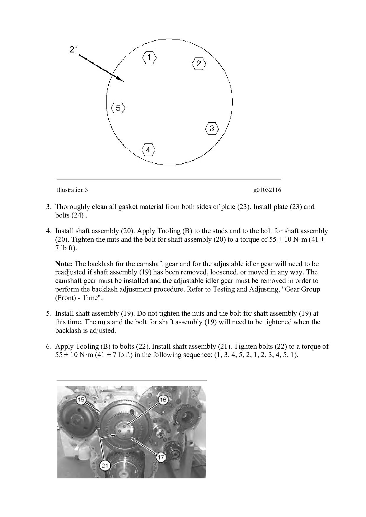
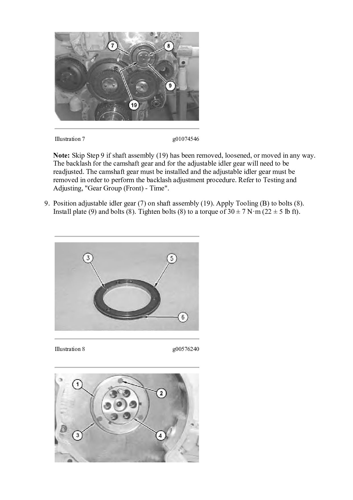
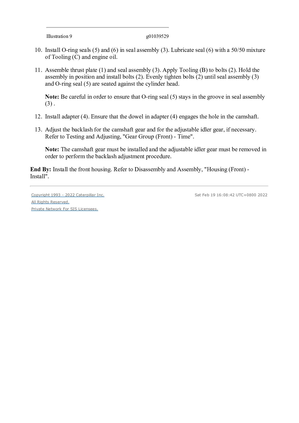
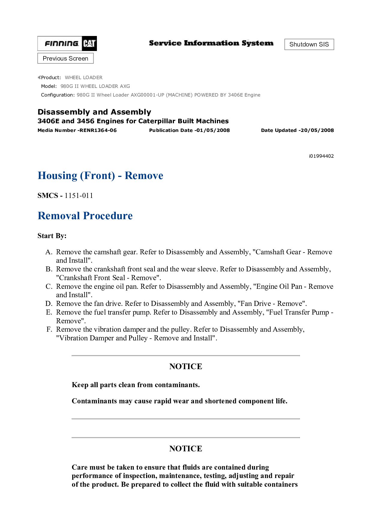
    both sides of plate (23). Install plate (23) and bolts (24) . 4. Install shaft assembly (20). Apply Tooling (B) to the studs and to the bolt for shaft assembly (20). Tighten the nuts and the bolt for shaft assembly (20) to a torque of 55 ± 10 N·m (41 ± 7 lb ft). Note: The backlash for the camshaft gear and for the adjustable idler gear will need to be readjusted if shaft assembly (19) has been removed, loosened, or moved in any way. The camshaft gear must be installed and the adjustable idler gear must be removed in order to perform the backlash adjustment procedure. Refer to Testing and Adjusting, "Gear Group (Front) - Time". 5. Install shaft assembly (19). Do not tighten the nuts and the bolt for shaft assembly (19) at this time. The nuts and the bolt for shaft assembly (19) will need to be tightened when the backlash is adjusted. 6. Apply Tooling (B) to bolts (22). Install shaft assembly (21). Tighten bolts (22) to a torque of 55 ± 10 N·m (41 ± 7 lb ft) in the following sequence: (1, 3, 4, 5, 2, 1, 2, 3, 4, 5, 1).
  4. Illustration 4 g01074541 Illustration 5 g00516404 7. Put cluster gear

    (15) on shaft assembly (21). Ensure that Timing Marks (V) are aligned on the cluster gear and on the crankshaft gear. Apply Tooling (B) to bolts (16). Install plate (17) and bolts (16). Tighten bolts (16) to a torque of 30 ± 7 N·m (22 ± 5 lb ft). Illustration 6 g01074542 8. Position idler gear (11) on shaft assembly (20). Apply Tooling (B) to bolts (12). Install plate (13) with the oil groove toward the gear face. Install bolts (12) and tighten the bolts to a torque of 30 ± 7 N·m (22 ± 5 lb ft).
  5. Illustration 7 g01074546 Note: Skip Step 9 if shaft assembly

    (19) has been removed, loosened, or moved in any way. The backlash for the camshaft gear and for the adjustable idler gear will need to be readjusted. The camshaft gear must be installed and the adjustable idler gear must be removed in order to perform the backlash adjustment procedure. Refer to Testing and Adjusting, "Gear Group (Front) - Time". 9. Position adjustable idler gear (7) on shaft assembly (19). Apply Tooling (B) to bolts (8). Install plate (9) and bolts (8). Tighten bolts (8) to a torque of 30 ± 7 N·m (22 ± 5 lb ft). Illustration 8 g00576240
  6. https://www.aservicemanualpdf.com/ My Dear Friend! Thank you very much for visiting.

    Full manual if required, please enter the following URL into your browser. https://www.aservicemanualpdf.com/
  7. Illustration 9 g01039529 10. Install O-ring seals (5) and (6)

    in seal assembly (3). Lubricate seal (6) with a 50/50 mixture of Tooling (C) and engine oil. 11. Assemble thrust plate (1) and seal assembly (3). Apply Tooling (B) to bolts (2). Hold the assembly in position and install bolts (2). Evenly tighten bolts (2) until seal assembly (3) and O-ring seal (5) are seated against the cylinder head. Note: Be careful in order to ensure that O-ring seal (5) stays in the groove in seal assembly (3) . 12. Install adapter (4). Ensure that the dowel in adapter (4) engages the hole in the camshaft. 13. Adjust the backlash for the camshaft gear and for the adjustable idler gear, if necessary. Refer to Testing and Adjusting, "Gear Group (Front) - Time". Note: The camshaft gear must be installed and the adjustable idler gear must be removed in order to perform the backlash adjustment procedure. End By: Install the front housing. Refer to Disassembly and Assembly, "Housing (Front) - Install". Copyright 1993 - 2022 Caterpillar Inc. All Rights Reserved. Private Network For SIS Licensees. Sat Feb 19 16:08:42 UTC+0800 2022
  8. Shutdown SIS Previous Screen Product: WHEEL LOADER Model: 980G II

    WHEEL LOADER AXG Configuration: 980G II Wheel Loader AXG00001-UP (MACHINE) POWERED BY 3406E Engine Disassembly and Assembly 3406E and 3456 Engines for Caterpillar Built Machines Media Number -RENR1364-06 Publication Date -01/05/2008 Date Updated -20/05/2008 i01994402 Housing (Front) - Remove SMCS - 1151-011 Removal Procedure Start By: A. Remove the camshaft gear. Refer to Disassembly and Assembly, "Camshaft Gear - Remove and Install". B. Remove the crankshaft front seal and the wear sleeve. Refer to Disassembly and Assembly, "Crankshaft Front Seal - Remove". C. Remove the engine oil pan. Refer to Disassembly and Assembly, "Engine Oil Pan - Remove and Install". D. Remove the fan drive. Refer to Disassembly and Assembly, "Fan Drive - Remove". E. Remove the fuel transfer pump. Refer to Disassembly and Assembly, "Fuel Transfer Pump - Remove". F. Remove the vibration damper and the pulley. Refer to Disassembly and Assembly, "Vibration Damper and Pulley - Remove and Install". NOTICE Keep all parts clean from contaminants. Contaminants may cause rapid wear and shortened component life. NOTICE Care must be taken to ensure that fluids are contained during performance of inspection, maintenance, testing, adjusting and repair of the product. Be prepared to collect the fluid with suitable containers
  9. before opening any compartment or disassembling any component containing fluids.

    Refer to Special Publication, NENG2500, "Caterpillar Tools and Shop Products Guide" for tools and supplies suitable to collect and contain fluids on Caterpillar products. Dispose of all fluids according to local regulations and mandates. Illustration 1 g00579579 NOTICE Do not turn the crankshaft or the camshaft while the camshaft gear is removed. If the front gear group is not correctly timed during installation, interference can occur between the pistons and the valves, resulting in damage to the engine. 1. Remove nut (1) from the stud.
  10. Illustration 2 g00579581 2. Remove bolts (4) that fasten front

    plate (3) to front housing (2) . Illustration 3 g00579582 3. Remove bolts (5), nut (6), and nuts (7) from front housing (2) .
  11. Illustration 4 g00579584 4. Remove front housing (2) . Illustration

    5 g00579585 5. Remove gasket (8) from front plate (3) .
  12. Copyright 1993 - 2022 Caterpillar Inc. All Rights Reserved. Private

    Network For SIS Licensees. Sat Feb 19 16:09:38 UTC+0800 2022
  13. Shutdown SIS Previous Screen Product: WHEEL LOADER Model: 980G II

    WHEEL LOADER AXG Configuration: 980G II Wheel Loader AXG00001-UP (MACHINE) POWERED BY 3406E Engine Disassembly and Assembly 3406E and 3456 Engines for Caterpillar Built Machines Media Number -RENR1364-06 Publication Date -01/05/2008 Date Updated -20/05/2008 i01994404 Housing (Front) - Install SMCS - 1151-012 Installation Procedure NOTICE Keep all parts clean from contaminants. Contaminants may cause rapid wear and shortened component life. NOTICE Do not turn the crankshaft or the camshaft while the camshaft gear is removed. If the front gear group is not correctly timed during installation, interference can occur between the pistons and the valves, resulting in damage to the engine.
  14. Illustration 1 g00579585 1. Thoroughly clean the old gasket material

    from front plate (3). Install a new gasket (8) on front plate (3) . Illustration 2 g00579584 2. Thoroughly clean the old gasket material from front housing (2) and install front housing (2) on the two dowel pins.
  15. Illustration 3 g00579582 3. Install bolts (5), nut (6), and

    nuts (7) on front housing (2) . Illustration 4 g00579581 4. Install bolts (4) that fasten front plate (3) to front housing (2) .
  16. Illustration 5 g00579579 5. Install nut (1) on the stud.

    End By: a. Install the vibration damper and the pulley. Refer to Disassembly and Assembly, "Vibration Damper and Pulley - Remove and Install". b. Install the fuel transfer pump. Refer to Disassembly and Assembly, "Fuel Transfer Pump - Install". c. Install the fan drive. Refer to Disassembly and Assembly, "Fan Drive - Install". d. Install the engine oil pan. Refer to Disassembly and Assembly, "Engine Oil Pan - Remove and Install". e. Install the crankshaft front seal and the wear sleeve. Refer to Disassembly and Assembly, "Crankshaft Front Seal - Install". f. Install the camshaft gear. Refer to Disassembly and Assembly, "Camshaft Gear - Remove and Install". Copyright 1993 - 2022 Caterpillar Inc. All Rights Reserved. Private Network For SIS Licensees. Sat Feb 19 16:10:34 UTC+0800 2022
  17. Shutdown SIS Previous Screen Product: WHEEL LOADER Model: 980G II

    WHEEL LOADER AXG Configuration: 980G II Wheel Loader AXG00001-UP (MACHINE) POWERED BY 3406E Engine Disassembly and Assembly 3406E and 3456 Engines for Caterpillar Built Machines Media Number -RENR1364-06 Publication Date -01/05/2008 Date Updated -20/05/2008 i01994409 Valve Mechanism Cover - Remove and Install SMCS - 1107-010 Removal Procedure NOTICE Keep all parts clean from contaminants. Contaminants may cause rapid wear and shortened component life.
  18. Illustration 1 g01033224 1. Remove bolts (1). 2. Remove valve

    mechanism cover (2). Installation Procedure NOTICE Keep all parts clean from contaminants. Contaminants may cause rapid wear and shortened component life.
  19. Illustration 2 g01033224 Illustration 3 g00579295 1. Position valve mechanism

    cover (2) on the valve cover base. Tighten bolts (1) to a torque of 18 ± 3 N·m (13 ± 2 lb ft) in the numerical sequence that is shown in Illustration 3.
  20. Copyright 1993 - 2022 Caterpillar Inc. All Rights Reserved. Private

    Network For SIS Licensees. Sat Feb 19 16:11:30 UTC+0800 2022
  21. Shutdown SIS Previous Screen Product: WHEEL LOADER Model: 980G II

    WHEEL LOADER AXG Configuration: 980G II Wheel Loader AXG00001-UP (MACHINE) POWERED BY 3406E Engine Disassembly and Assembly 3406E and 3456 Engines for Caterpillar Built Machines Media Number -RENR1364-06 Publication Date -01/05/2008 Date Updated -20/05/2008 i01985327 Valve Mechanism Cover Base - Remove and Install SMCS - 1120-010 Removal Procedure Start By: a. Remove the valve mechanism covers. Refer to Disassembly and Assembly, "Valve Mechanism Cover - Remove and Install". NOTICE Keep all parts clean from contaminants. Contaminants may cause rapid wear and shortened component life.
  22. Illustration 1 g01028794 1. Disconnect harness assembly (3) from the

    electronic unit injector. 2. Disconnect harness assembly (1) from valve cover base (2). 3. Remove bolts (4). 4. Remove valve cover base (2). Installation Procedure NOTICE Keep all parts clean from contaminants. Contaminants may cause rapid wear and shortened component life. Note: Before assembly, check the condition of the seal. If the seal is worn or damaged, use a new part for replacement.
  23. Illustration 2 g01028794 Illustration 3 g00579307 1. Position valve cover

    base (2) on the cylinder head and install bolts (4). Tighten bolts (4) to a torque of 18 ± 3 N·m (13 ± 2 lb ft) in the numerical sequence that is shown in Illustration 3. 2. Connect harness assembly (1).
  24. 3. Position harness assembly (3) on the electronic unit injector.

    Tighten the cap nuts to a torque of 2.5 ± 0.25 N·m (22 ± 2 lb in). End By: a. Install the valve mechanism covers. Refer to Disassembly and Assembly, "Valve Mechanism Cover - Remove and Install". Copyright 1993 - 2022 Caterpillar Inc. All Rights Reserved. Private Network For SIS Licensees. Sat Feb 19 16:12:25 UTC+0800 2022
  25. Shutdown SIS Previous Screen Product: WHEEL LOADER Model: 980G II

    WHEEL LOADER AXG Configuration: 980G II Wheel Loader AXG00001-UP (MACHINE) POWERED BY 3406E Engine Disassembly and Assembly 3406E and 3456 Engines for Caterpillar Built Machines Media Number -RENR1364-06 Publication Date -01/05/2008 Date Updated -20/05/2008 i01994416 Compression Brake - Remove - If Equipped SMCS - 1119-011 Removal Procedure Start By: A. Remove the valve mechanism covers. Refer to Disassembly and Assembly, "Valve Mechanism Cover - Remove and Install". NOTICE Keep all parts clean from contaminants. Contaminants may cause rapid wear and shortened component life. NOTICE Care must be taken to ensure that fluids are contained during performance of inspection, maintenance, testing, adjusting and repair of the product. Be prepared to collect the fluid with suitable containers before opening any compartment or disassembling any component containing fluids. Refer to Special Publication, NENG2500, "Caterpillar Tools and Shop Products Guide" for tools and supplies suitable to collect and contain fluids on Caterpillar products. Dispose of all fluids according to local regulations and mandates.
  26. Illustration 1 g00619974 Note: The removal procedure is identical for

    all three compression brake housings. 1. Disconnect wires (4) . 2. Remove bolts (1) and bolts (2) . 3. Remove nut (3) . Note: Some of the early 340, 340A, and 340B compression brakes utilized two mounting studs that are located in the front of the brake housing. 4. Remove compression brake housing (5) . Copyright 1993 - 2022 Caterpillar Inc. All Rights Reserved. Private Network For SIS Licensees. Sat Feb 19 16:13:21 UTC+0800 2022
  27. Shutdown SIS Previous Screen Product: WHEEL LOADER Model: 980G II

    WHEEL LOADER AXG Configuration: 980G II Wheel Loader AXG00001-UP (MACHINE) POWERED BY 3406E Engine Disassembly and Assembly 3406E and 3456 Engines for Caterpillar Built Machines Media Number -RENR1364-06 Publication Date -01/05/2008 Date Updated -20/05/2008 i01933918 Compression Brake - Disassemble - If Equipped SMCS - 1119-015 Disassembly Procedure Table 1 Required Tools Tool Part Number Part Description Qty A 134-2837 Piston Compressor 1 Start By: A. Remove the compression brake. Refer to Disassembly and Assembly, "Compression Brake - Remove". NOTICE Keep all parts clean from contaminants. Contaminants may cause rapid wear and shortened component life. NOTICE Care must be taken to ensure that fluids are contained during performance of inspection, maintenance, testing, adjusting and repair of the product. Be prepared to collect the fluid with suitable containers before opening any compartment or disassembling any component containing fluids.
  28. Refer to Special Publication, NENG2500, "Caterpillar Tools and Shop Products

    Guide" for tools and supplies suitable to collect and contain fluids on Caterpillar products. Dispose of all fluids according to local regulations and mandates. Illustration 1 g00512487 Typical example NOTICE Do not disassemble or tamper with the solenoid valve. Engine damage could result. 1. Remove solenoid valve (1) . 2. Remove seals (2) from the solenoid valve. Remove seal (2) from the bottom of the bore for the solenoid valve. Discard the seals. 3. Wash solenoid valve (1) with approved cleaning solvent. Use a brush to clean the oil screen. Dry solenoid valve (1) with 103 to 138 kPa (15 to 20 psi) of compressed air.
  29. Illustration 2 g01009776 Typical example Remove control valve covers carefully.

    Control valve spring covers are under load from the control valve springs. Remove with care to avoid personal injury. Personal injury can result from parts and/or covers under spring pressure. Spring force will be released when covers are removed. Be prepared to hold spring loaded covers as the bolts are loosened. 4. Compress control valve cover (3) in order to relieve any spring pressure when allen head screw (4) is removed. 5. Remove allen head screw (4) . 6. Slowly remove control valve cover (3) in order to relieve spring tension force. Then remove control springs (6) .
  30. Please write to us. Our email: [email protected] Please go to

    the homepage to get the full manual, or other brand PDF manuals. Home Site: aservicemanualpdf.com
  31. Thank you very much for your reading. Please Click Here.

    Then Get COMPLETE MANUAL. NO WAITING NOTE: If there is no response to click on the link above, please download the PDF document first and then click on it.
  32. 7. Remove control valve (5) . Illustration 3 g01009783 Typical

    example NOTICE Do not diassemble or tamper with slave piston adjusting screw. Engine damage could result. 8. Loosen slave piston adjustment screw locknut (8) and loosen slave piston adjustment screw (7) until the slave piston is fully retracted. Slave piston adjusting screw (7) should be loose.
  33. Illustration 5 g01009784 Typical example Remove slave pistons carefully. The

    slave pistons are under spring pressure. Remove with care to avoid personal injury. 10. Slowly turn the handle on Tooling (A) until retaining washer (13) is compressed approximately 1.00 mm (0.040 inch) in order to relieve the spring pressure from retaining ring (14) . 11. Remove retaining ring (14) for the slave piston. Back out the handle on Tooling (A) until the springs are loose. Remove Tooling (A) . 12. Remove retaining washer (13), and the inner spring (12), pushrod (11), outer spring (10), and slave piston (9). Ensure that the components are not in a bind. Components must be free of metal burrs. 13. Clean the components with an approved cleaning solvent. Inspect the contact point between slave piston (9) and pushrod (11). Inspect the other components for damage or wear. Components that are pitted, cracked, or galled should be replaced with new parts.
  34. https://www.aservicemanualpdf.com/ My Dear Friend! Thank you very much for visiting.

    Full manual if required, please enter the following URL into your browser. https://www.aservicemanualpdf.com/