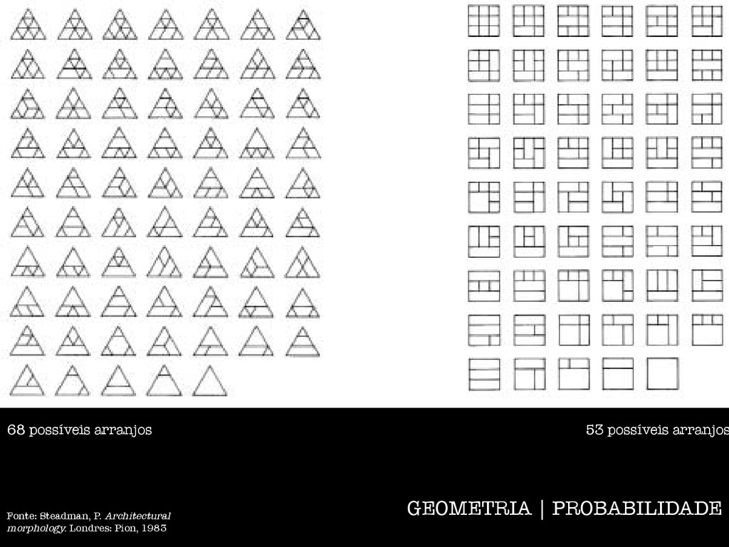
units, although more numerous, cannot 11 12 13 9 Plan of Sundt house project by Frank Lloyd Wright, 1941, laid out on a triangular grid 10 Plan of house for Joe Price by Bruce Goff, Bartlesville, Oklahoma, 1956-, also laid out on a triangular grid 11 Fragments of grids, each comprised of nine cells whose shapes are squares, equilateral triangles, and regular hexagons 12 The six possible convex shapes made by aggregating unit cells in the square grid of Figure 11 13 The 10 possible convex shapes made by aggregating unit cells in the triangular grid of Figure 11 15 14 All 53 possible arrangements in which combinations of the rectangular shapes shown in Figure 12 can be packed, without interstices, into the 15 All 68 possible arrangements in which combinations of the shapes shown in Figure 13 can be packed, without interstices, into the triangular grid of 68 possíveis arranjos 53 possíveis arranjos Fonte: Steadman, P. Architectural morphology. Londres: Pion, 1983
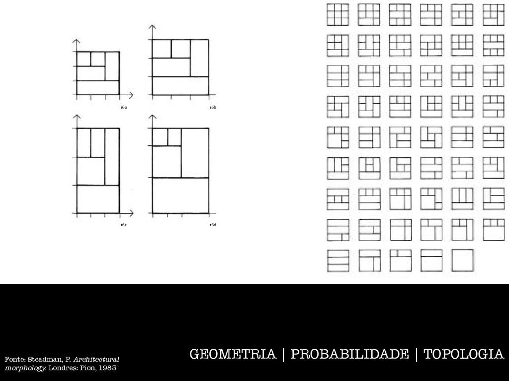
aggregating triangular units, although more numerous, cannot 11 12 13 9 Plan of Sundt house project by Frank Lloyd Wright, 1941, laid out on a triangular grid 10 Plan of house for Joe Price by Bruce Goff, Bartlesville, Oklahoma, 1956-, also laid out on a triangular grid 11 Fragments of grids, each comprised of nine cells whose shapes are squares, equilateral triangles, and regular hexagons 12 The six possible convex shapes made by aggregating unit cells in the square grid of Figure 11 13 The 10 possible convex shapes made by aggregating unit cells in the triangular grid of Figure 11 arrangements of shapes than does the square grid. 16a 16b stretched, by a shear transformation c The same packing stretched, by a shear of octagons and squares 17a 17b 16c 16d 17c 17d Fonte: Steadman, P. Architectural morphology. Londres: Pion, 1983
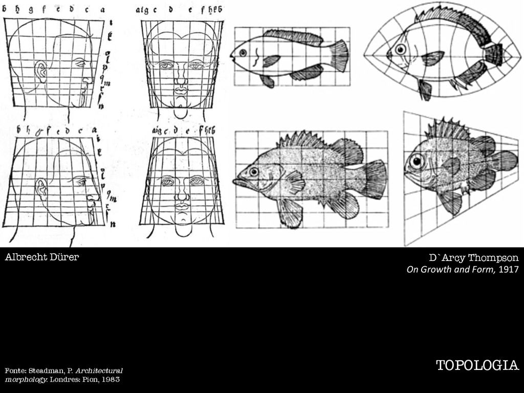
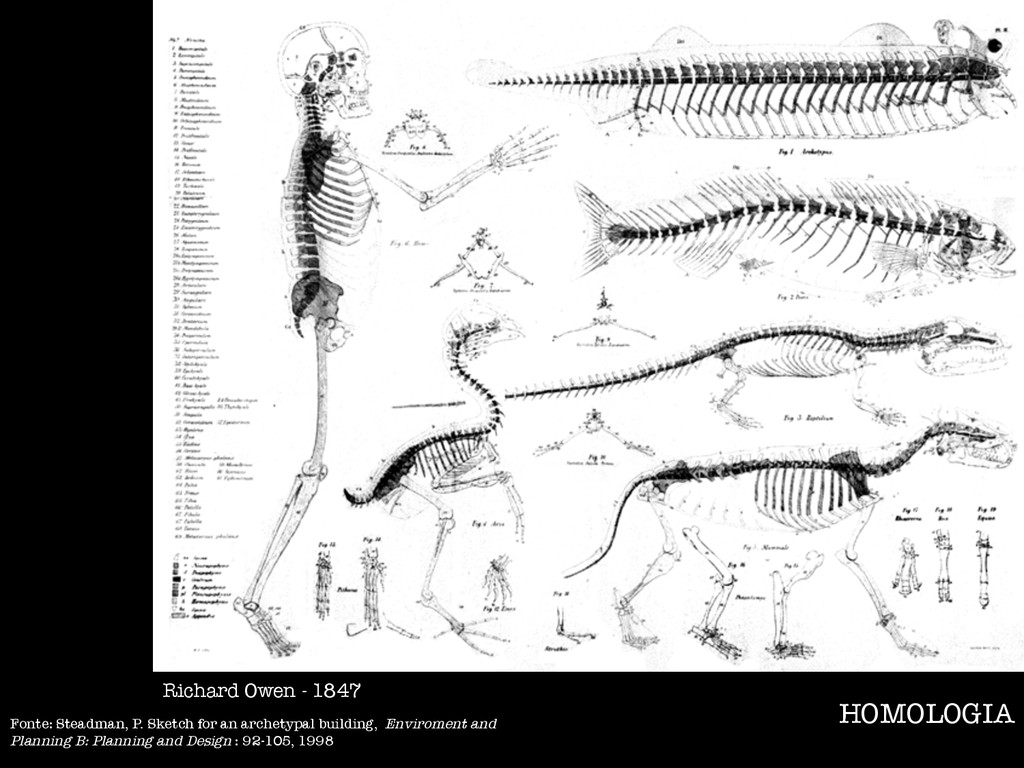
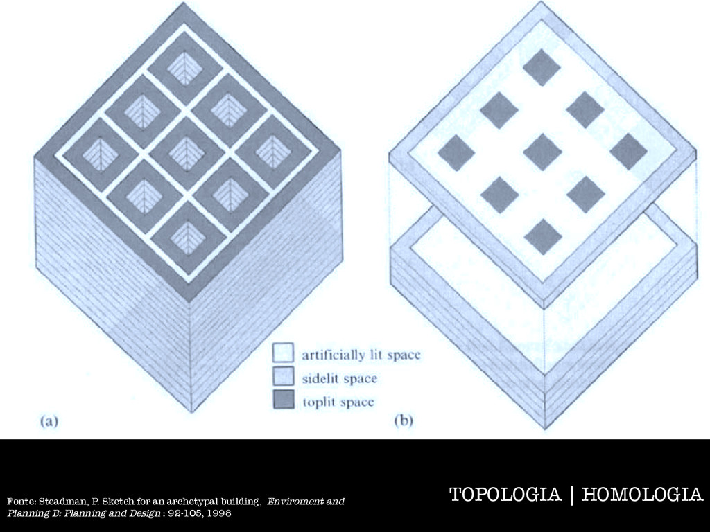
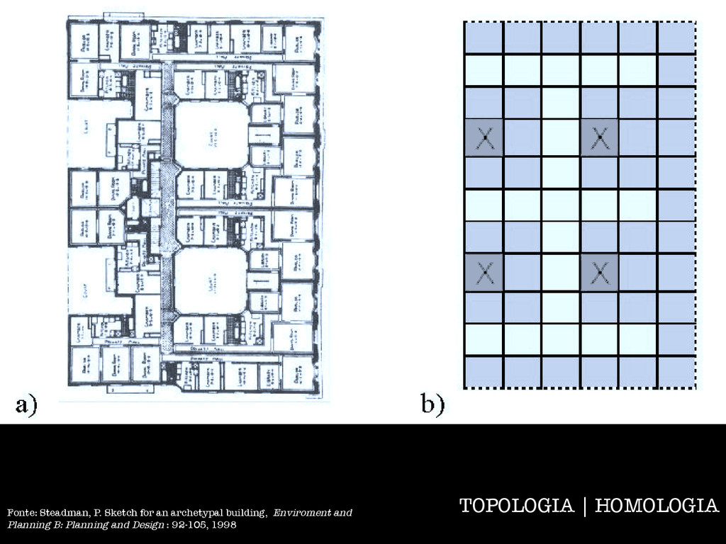
a) The archetypal form. b) TOPOLOGIA | HOMOLOGIA Fonte: Steadman, P. Sketch for an archetypal building, Enviroment and Planning B: Planning and Design : 92-105, 1998
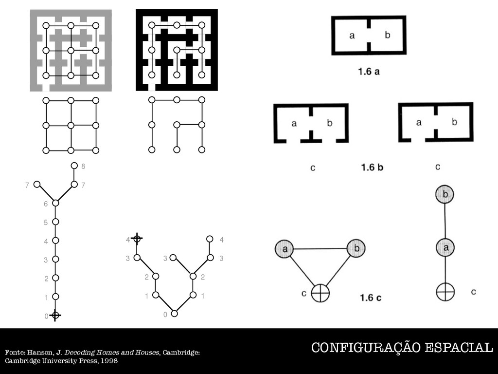
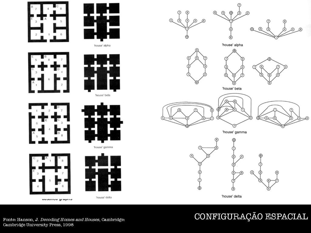
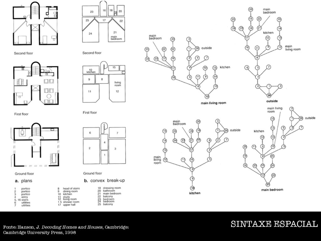
reaking the the nodes) he attern. notypes ial he ving lation all of nique aph is a kinship, e Figure 1. Adjacency Graph Figure 2. Permeability Graph page 2 relations as a graph and analysing the by treating them as elements (or nodes) ge; erns such as those often found in the tures, or different types of urban pattern. hemes across different cultural genotypes ltural comparative analysis of spatial lture and social behaviour. This is the echniques are techniques for observing cal techniques for analysing the relation w they are used. We will deal with all of with space syntax as a set of technique re around the idea of a graph. A graph is a ns between elements: relations of kinship, on, amongst spaces, and so on. The a small circle, or node, and the relation with oining the circles. There are two obvious gs: to make a graph of the adjacency ms (see Figure 1), which is called an ph of the access relations between the which is called a permeability graph, or not be a relation of direct permeability cency (but not vice versa). The access graph acency graph. permeability rather than adjacency (for n's Architectural Morphology), because this is a building. The simplest kind of permeability ies of a space define each spatial element. We ure 3). Figure 2. Permeability Graph Figure 3. Plan and Boundary Graph Figure 4a. Plan and its corresponding Permeability Graph 0 1 2 3 4 5 6 7 7 8 s r u e root el of ginal ed to the two f you u have he ally and like a f ation n an and ns. Figure 4b. Justified Permeability Graph from the carrier space (outside space) with depths indicated. 4 5 page 3 0 1 2 3 4 5 6 7 7 depth until you have made all the links and shown all the spaces in the original permeability graph. If in doubt, number up you unjustified graph from the chosen root: all spaces directly connected to it are at level one, all connected to that at level two and so on (Figure 4c). The numbers should step out from the root evenly. If you have a jump of more than one whole number between two points directly joined by a line you have numbered the graph incorrectly. If you have crossed a line more than one level of depth in the justified graph, you have drawn one or more spaces at the wrong levels of depth. If you draw up the justified graph from different roots, you will see that the shape of the graph changes (see Figure 5). This is because spaces are normally differentially related within the configuration as a whole. It is not worth redrawing graphs to show what it looks like from each and every point, especially for large complexes of rooms, but it is often worth looking for a particularly well-connected space somewhere in the heart of the complex, and drawing it from there or even redrawing from an important labelled space like a courtyard. Drawing graphs from different points in a configuration is a graphic way of illustrating how more integrated spaces pull the configuration close to the root and how more segregated spaces push the remainder of the configuration away. The shape of the graph captures a depth distribution from a point in an overall shape. This shape will show how examples differ in terms of depth and rings, the two fundamental syntactic properties of all spatial configurations. Figure 4b. Justified Permeability Graph from the carrier space (outside space) with depths indicated. 0 1 2 3 4 5 6 7 7 8 Figure 4c. Unjustified Permeability Graph from the carrier space (outside space) with depths indicated. Figure 5a. Unjustified Permeability Graph with depths from the root indicated at depth 0. 4 3 2 1 0 1 2 3 3 4 1 0 1 2 2 3 3 3 4 4 Figure 5b. Justified Permeability Graph with depths from the root indicated at depth 0. CONFIGURAÇÃO ESPACIAL Fonte: Hanson, J. Decoding Homes and Houses, Cambridge: Cambridge University Press, 1998
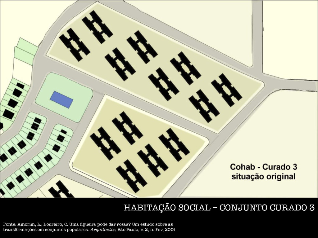
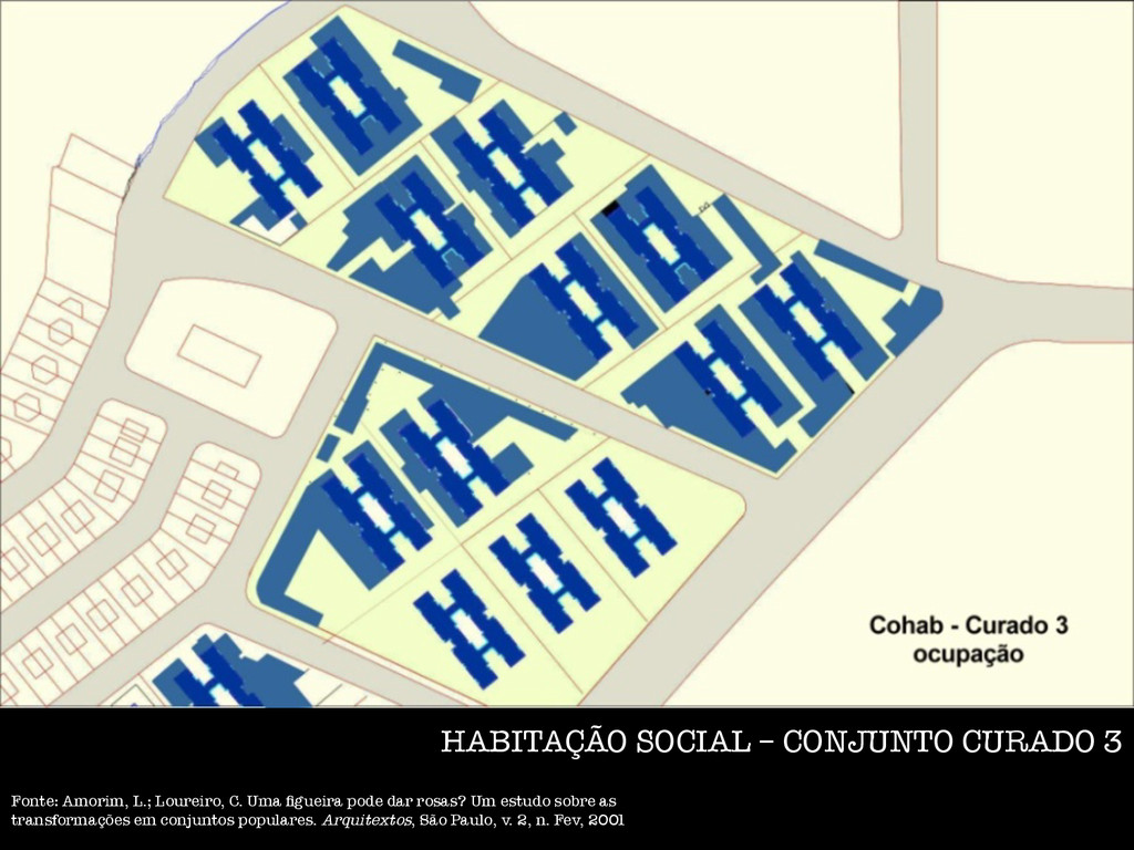
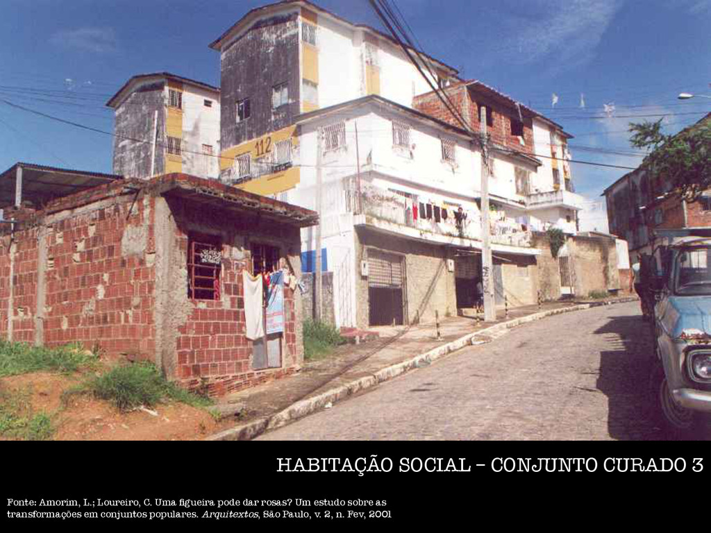
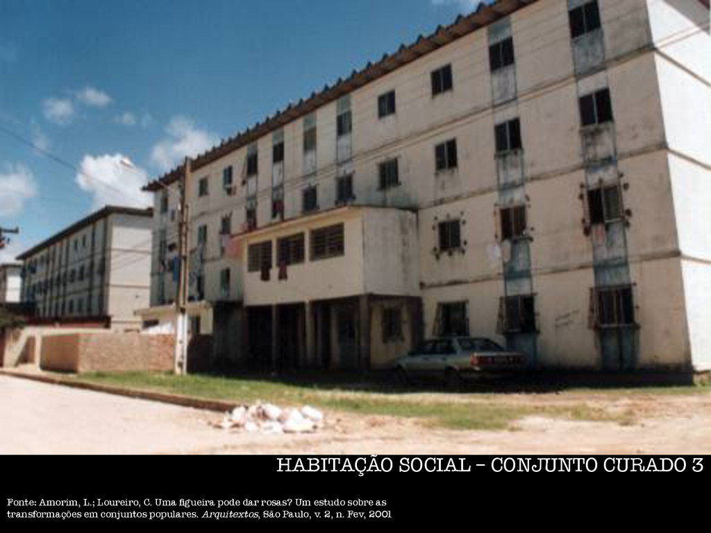
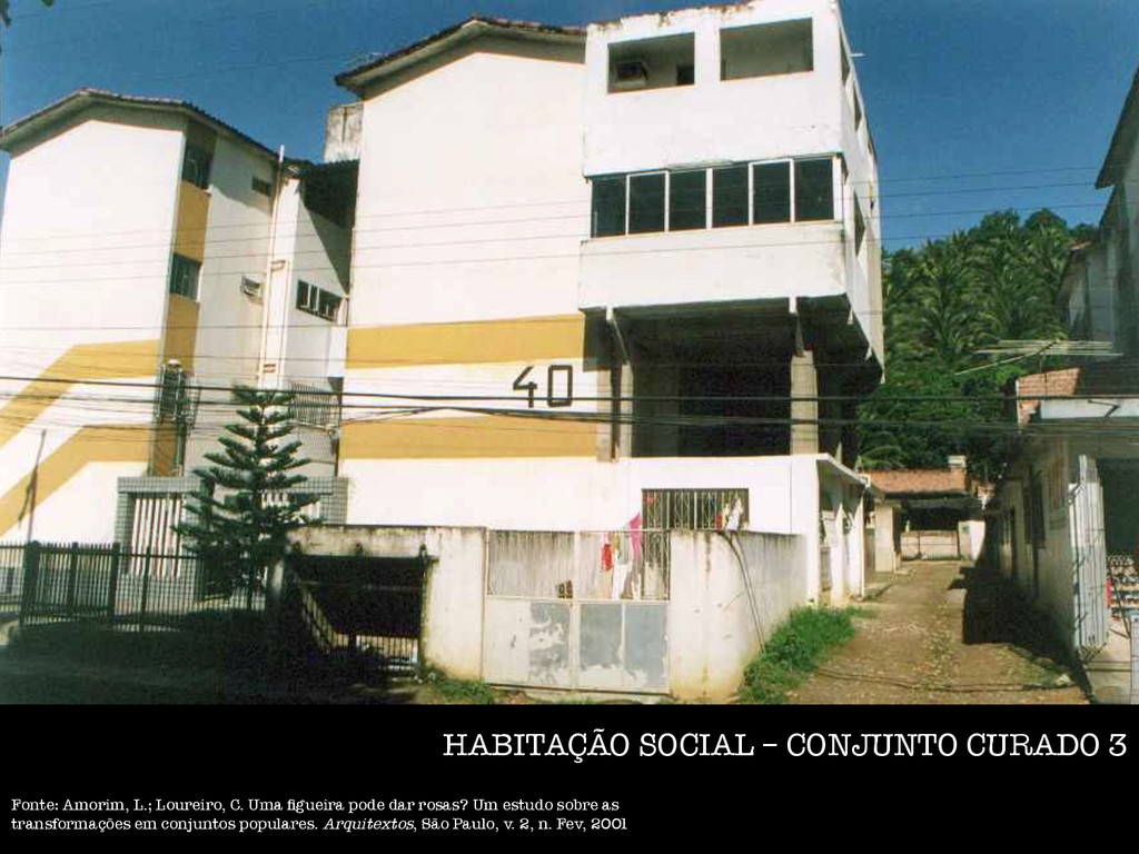
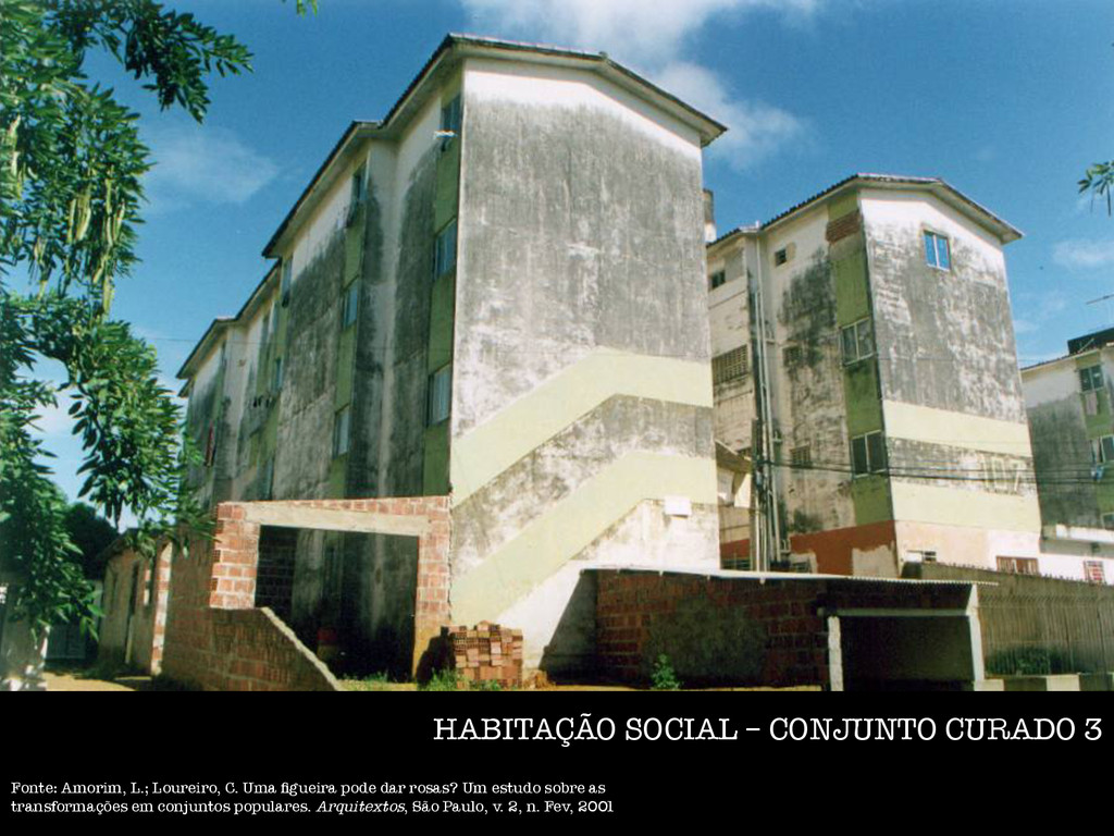
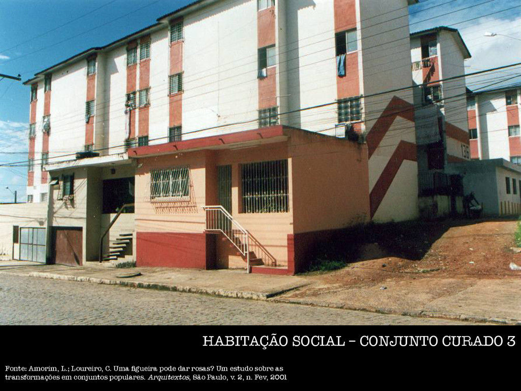
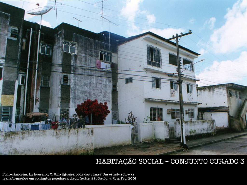
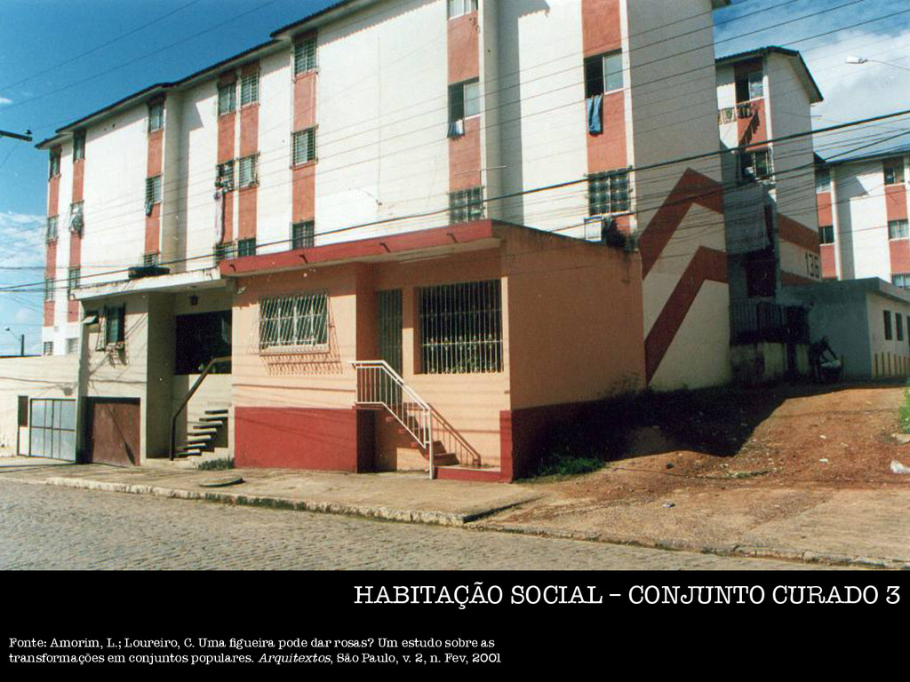
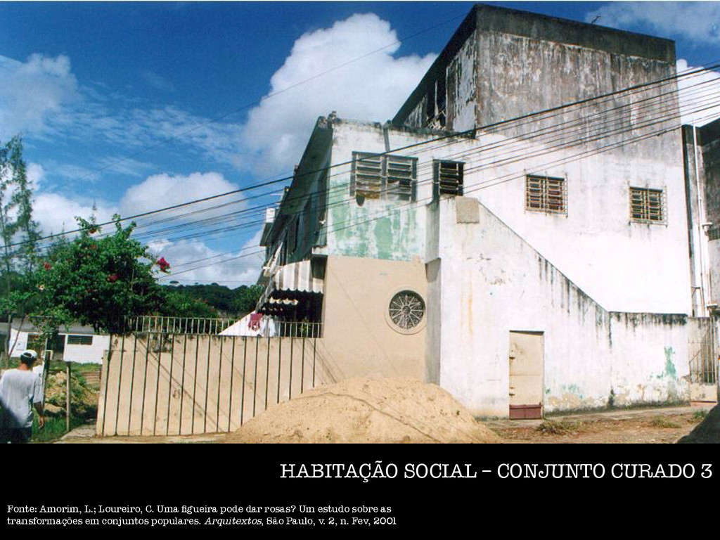
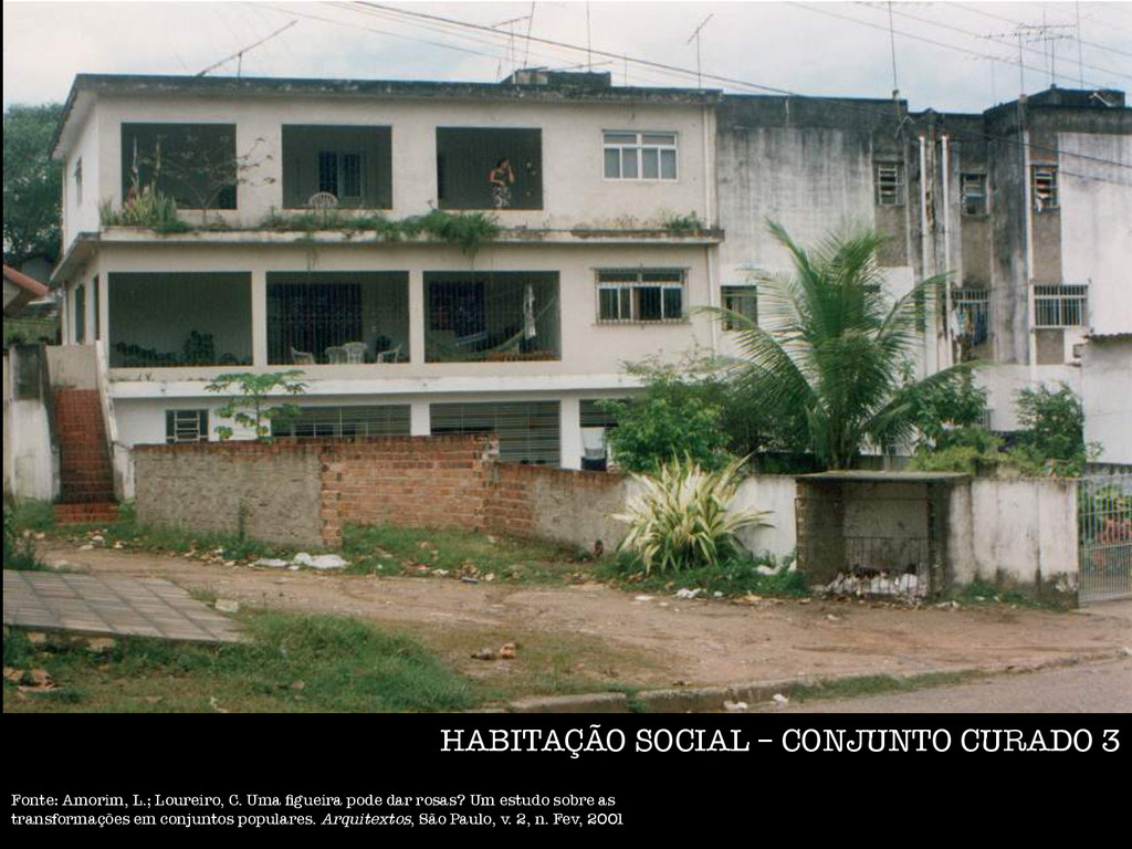
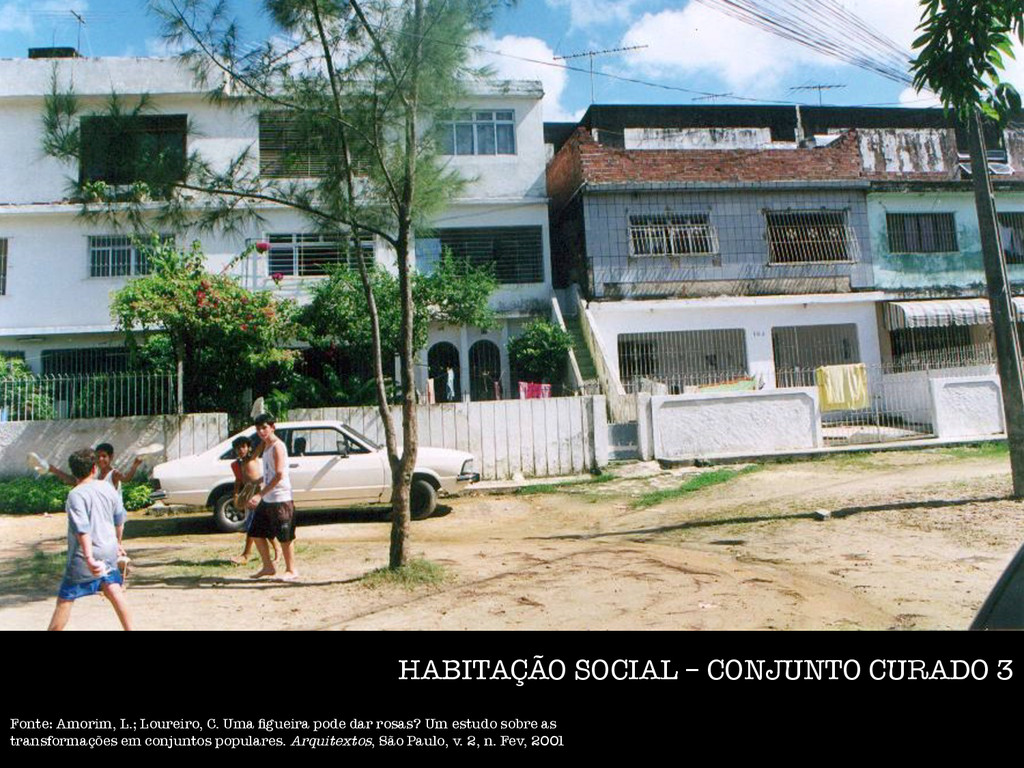
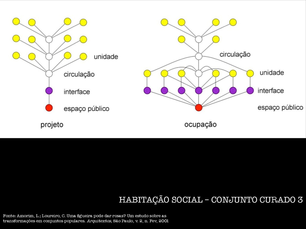
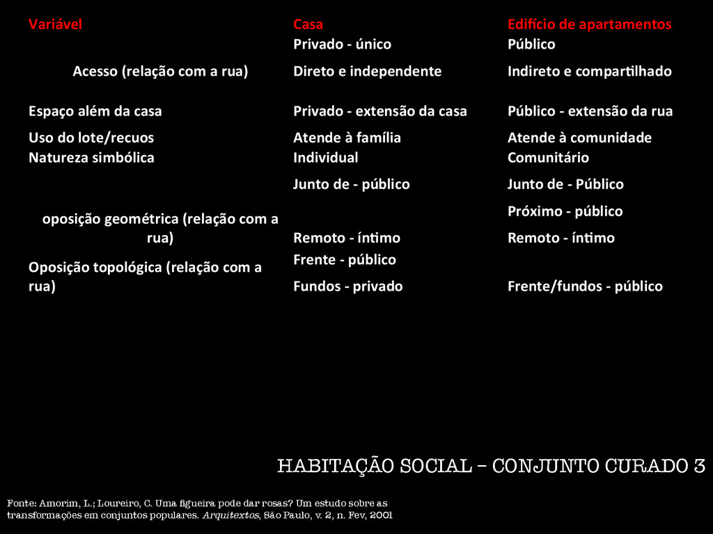
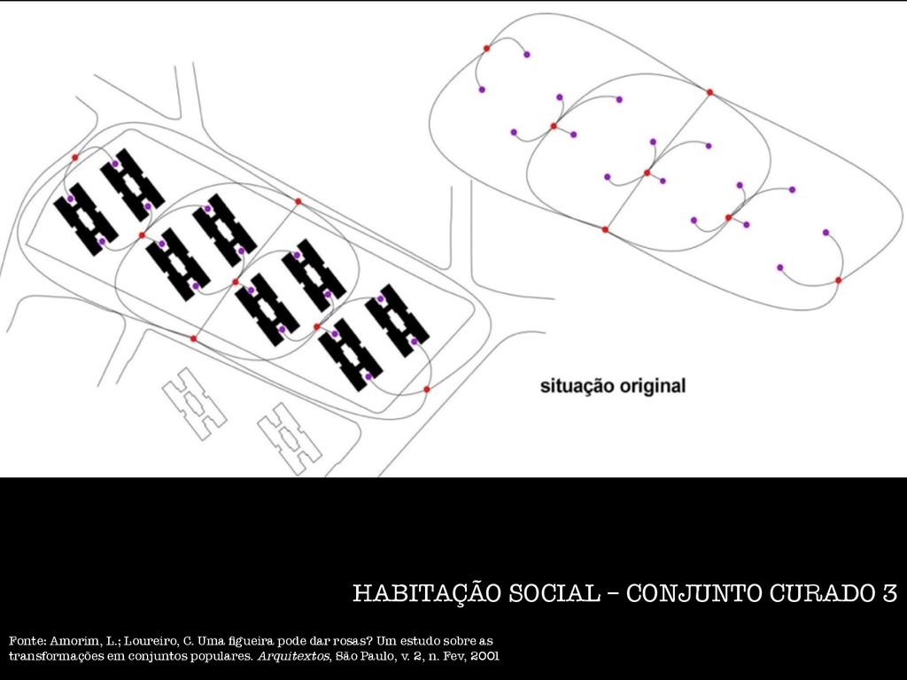
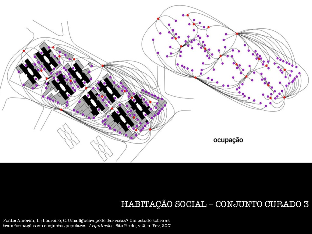
CASA ISOLADA. Variável Casa Edi.cio de apartamentos Acesso (relação com a rua) Privado -‐ único Público Direto e independente Indireto e comparAlhado Espaço além da casa Privado -‐ extensão da casa Público -‐ extensão da rua Uso do lote/recuos Atende à família Atende à comunidade Natureza simbólica Individual Comunitário oposição geométrica (relação com a rua) Junto de -‐ público Junto de -‐ Público Remoto -‐ ínAmo Próximo -‐ público Remoto -‐ ínAmo Oposição topológica (relação com a rua) Frente -‐ público Frente/fundos -‐ público Fundos -‐ privado HABITAÇÃO SOCIAL – CONJUNTO CURADO 3 Fonte: Amorim, L.; Loureiro, C. Uma figueira pode dar rosas? Um estudo sobre as transformações em conjuntos populares. Arquitextos, São Paulo, v. 2, n. Fev, 2001
como parte da Escola de Química da Universidade do Recife; Idealizado e dirigido pelo professor Oswaldo Gonçalves de Lima parte da Escola de Química como “um organismo satélite na esfera técnico-científica do ensino superior, semi-auto-suficiente relativamente à Escola Mater” (UNIVERSIDADE DO RECIFE, 1955, p. s/n); Desenvolver atividades de pesquisa nos campos de química, microbiologia e farmacologia; Ordens institucionais: a. uma organização gestora, hierárquica, centralizada na direção executiva e conselhos gestores; b. uma organização científica, fundamentada na relação entre as diversas unidades laboratoriais e seus respectivos suportes. CRIAÇÃO OBJETIVOS ORGANIZAÇÃO SOCIAL
química – extração de substâncias ativas da flora nativa; b. Microbiologia – teste de eficiência das drogas; c. Farmacologia – produção de agentes ativos, após avaliações sistemáticas em cobaias. A ordem social é alterada pelo n.º 62.483, de 1º de abril de 1968, que extinguiu as unidades exclusivamente dedicadas à pesquisa. Pesquisadores passam a ser docentes.. O Instituto, passa a Departamento, fica subordinado ao Centro de Ciências Biológicas: a. redução de sua autonomia gestora e de sua importância hierárquica na universidade; b. introdução das atividades pedagógicas, em consonância com as de pesquisa, e conseqüente criação de unidades de gestão, pessoal e pedagógica, fragmentando o modelo gestor original; CICLO DE INVESTIGAÇÃO ALTERAÇÃO DA ORDEM SOCIAL
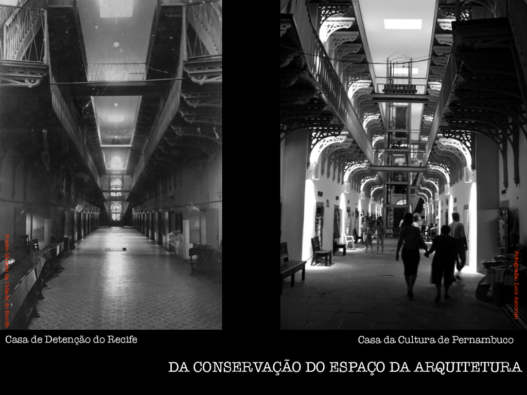
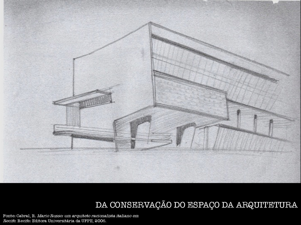
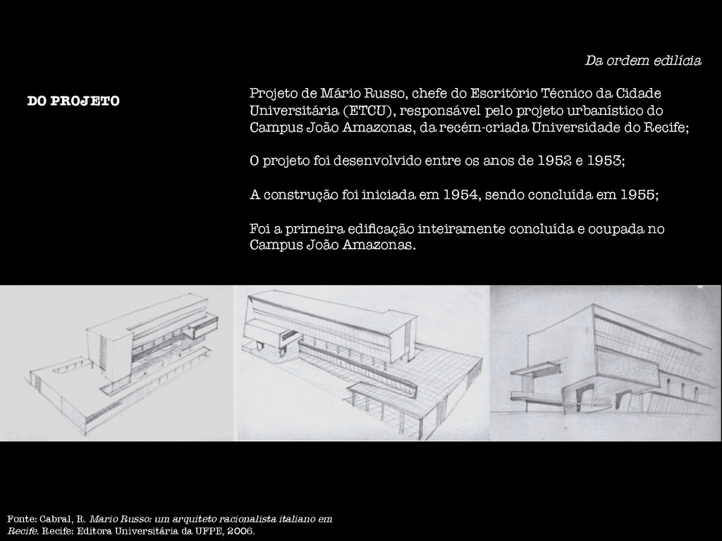
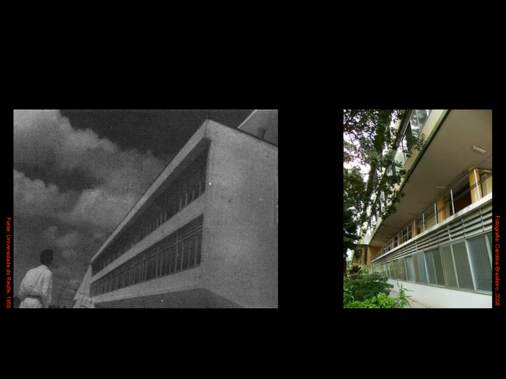
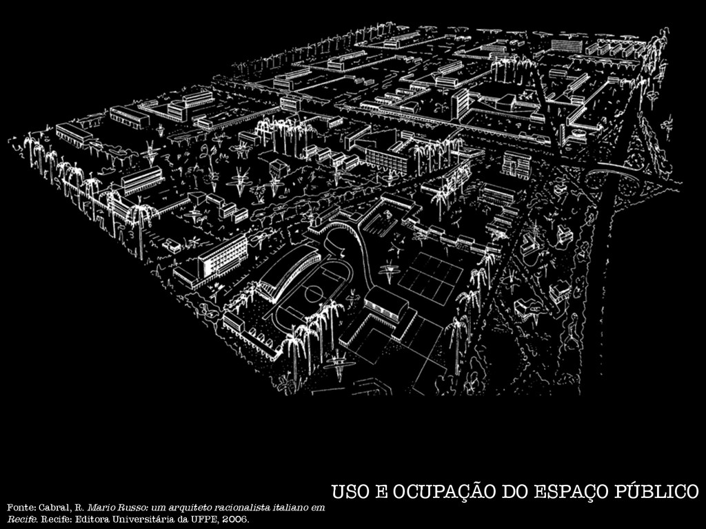
Técnico da Cidade Universitária (ETCU), responsável pelo projeto urbanístico do Campus João Amazonas, da recém-criada Universidade do Recife; O projeto foi desenvolvido entre os anos de 1952 e 1953; A construção foi iniciada em 1954, sendo concluída em 1955; Foi a primeira edificação inteiramente concluída e ocupada no Campus João Amazonas. Fonte: Cabral, R. Mario Russo: um arquiteto racionalista italiano em Recife. Recife: Editora Universitária da UFPE, 2006. DO PROJETO
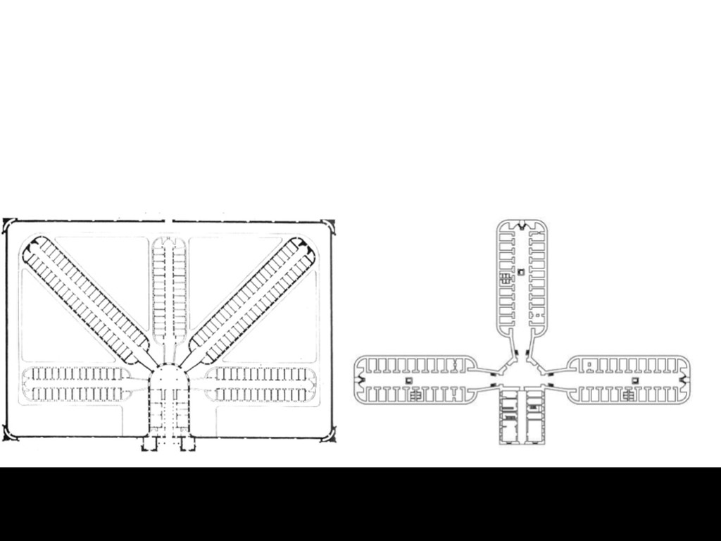
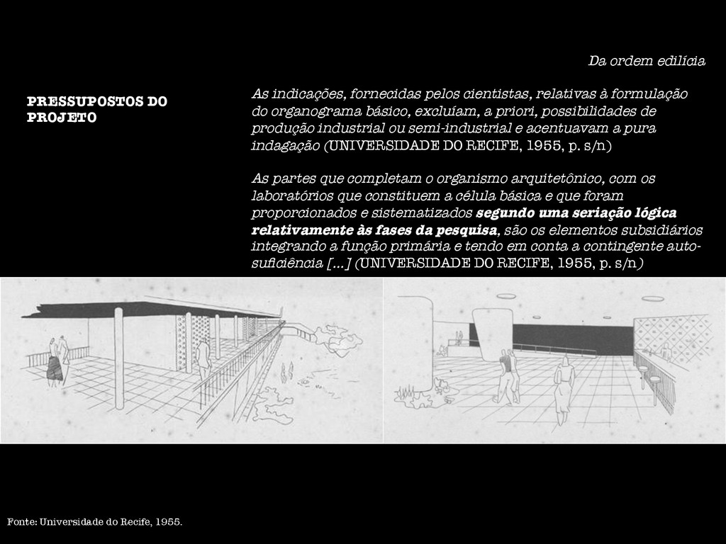
formulação do organograma básico, excluíam, a priori, possibilidades de produção industrial ou semi-industrial e acentuavam a pura indagação (UNIVERSIDADE DO RECIFE, 1955, p. s/n) As partes que completam o organismo arquitetônico, com os laboratórios que constituem a célula básica e que foram proporcionados e sistematizados segundo uma seriação lógica relativamente às fases da pesquisa, são os elementos subsidiários integrando a função primária e tendo em conta a contingente auto- suficiência [...] (UNIVERSIDADE DO RECIFE, 1955, p. s/n) PRESSUPOSTOS DO PROJETO Fonte: Universidade do Recife, 1955.
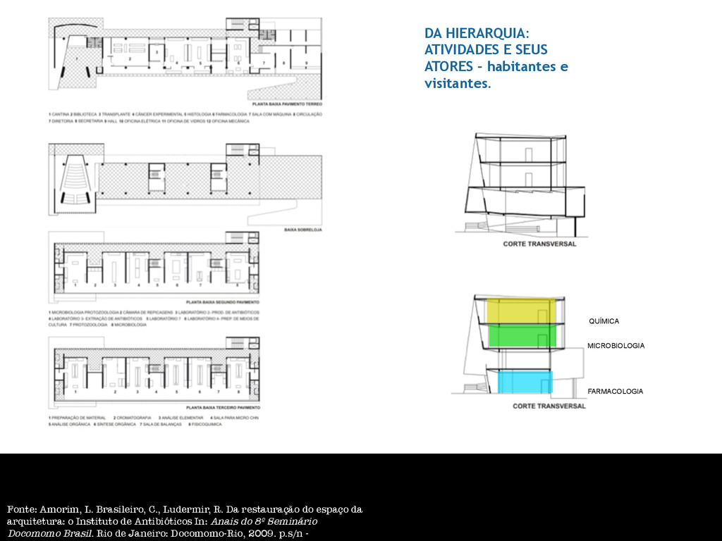
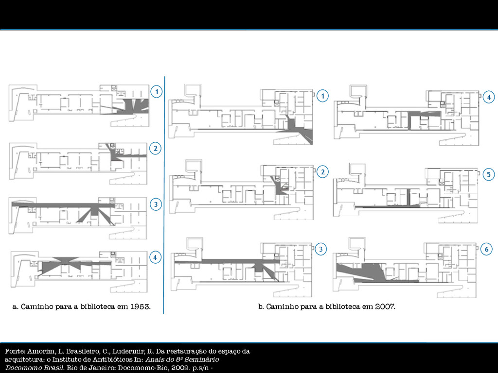
habitantes e visitantes. Fonte: Amorim, L. Brasileiro, C., Ludermir, R. Da restauração do espaço da arquitetura: o Instituto de Antibióticos In: Anais do 8º Seminário Docomomo Brasil. Rio de Janeiro: Docomomo-Rio, 2009. p.s/n -
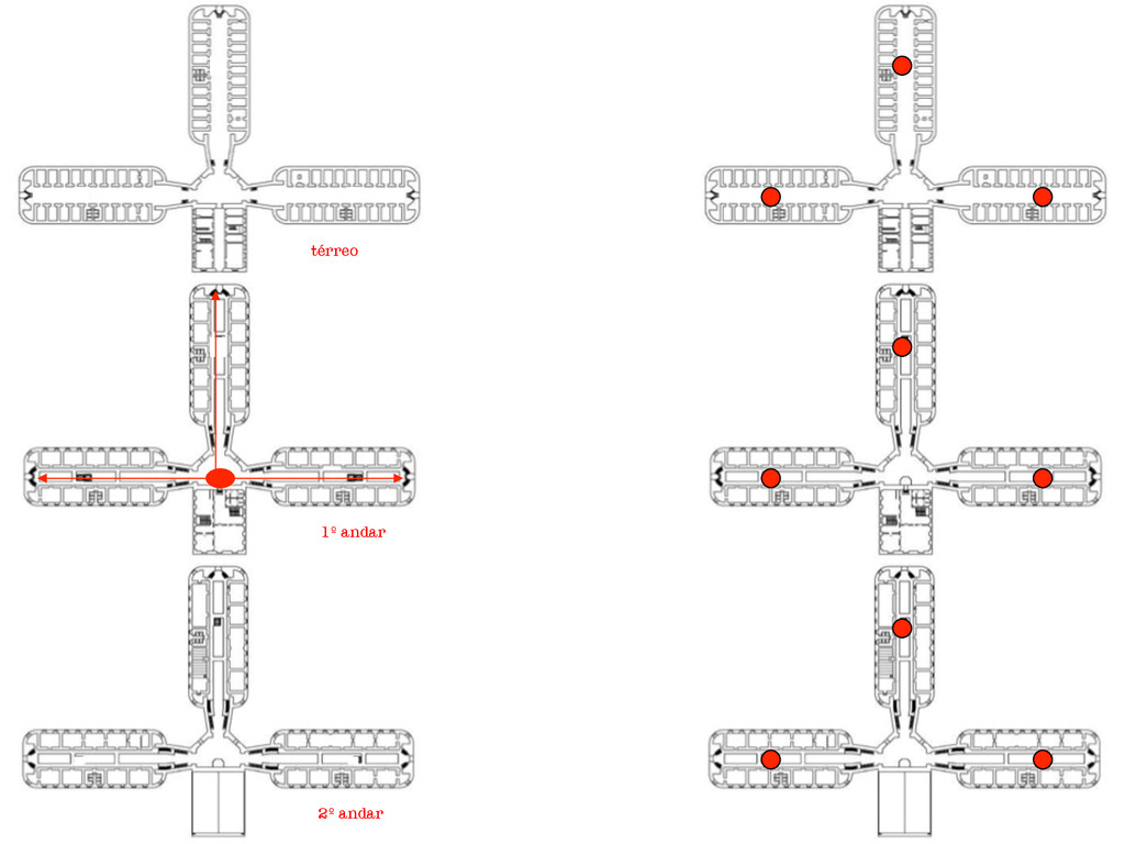
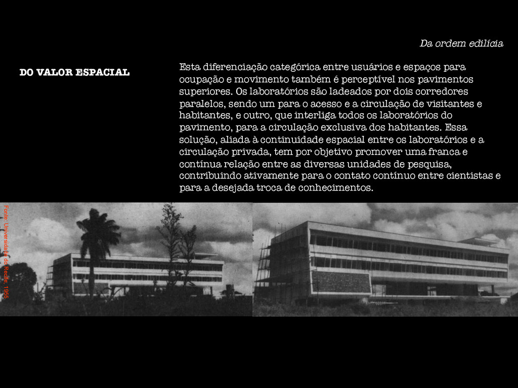
para ocupação e movimento também é perceptível nos pavimentos superiores. Os laboratórios são ladeados por dois corredores paralelos, sendo um para o acesso e a circulação de visitantes e habitantes, e outro, que interliga todos os laboratórios do pavimento, para a circulação exclusiva dos habitantes. Essa solução, aliada à continuidade espacial entre os laboratórios e a circulação privada, tem por objetivo promover uma franca e contínua relação entre as diversas unidades de pesquisa, contribuindo ativamente para o contato contínuo entre cientistas e para a desejada troca de conhecimentos. DO VALOR ESPACIAL Fonte: Universidade do Recife, 1955
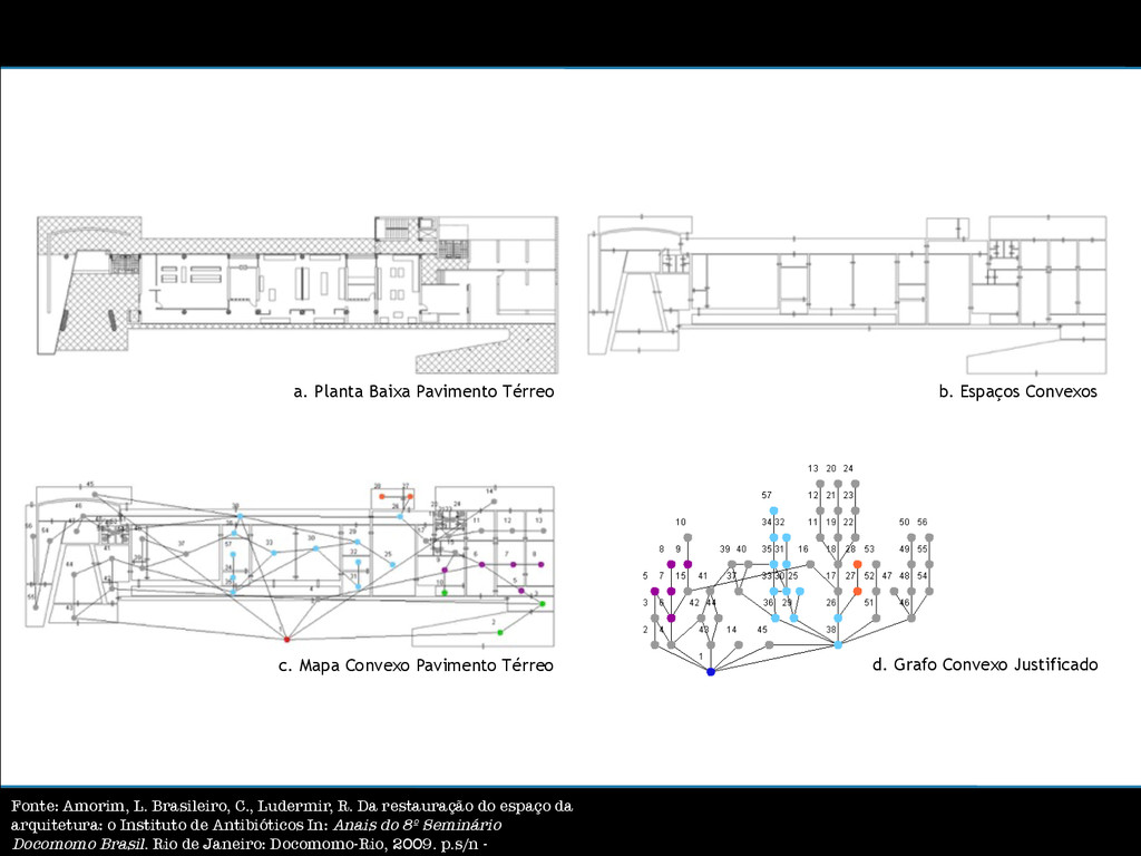
d. Grafo Convexo Justificado b. Espaços Convexos Fonte: Amorim, L. Brasileiro, C., Ludermir, R. Da restauração do espaço da arquitetura: o Instituto de Antibióticos In: Anais do 8º Seminário Docomomo Brasil. Rio de Janeiro: Docomomo-Rio, 2009. p.s/n -
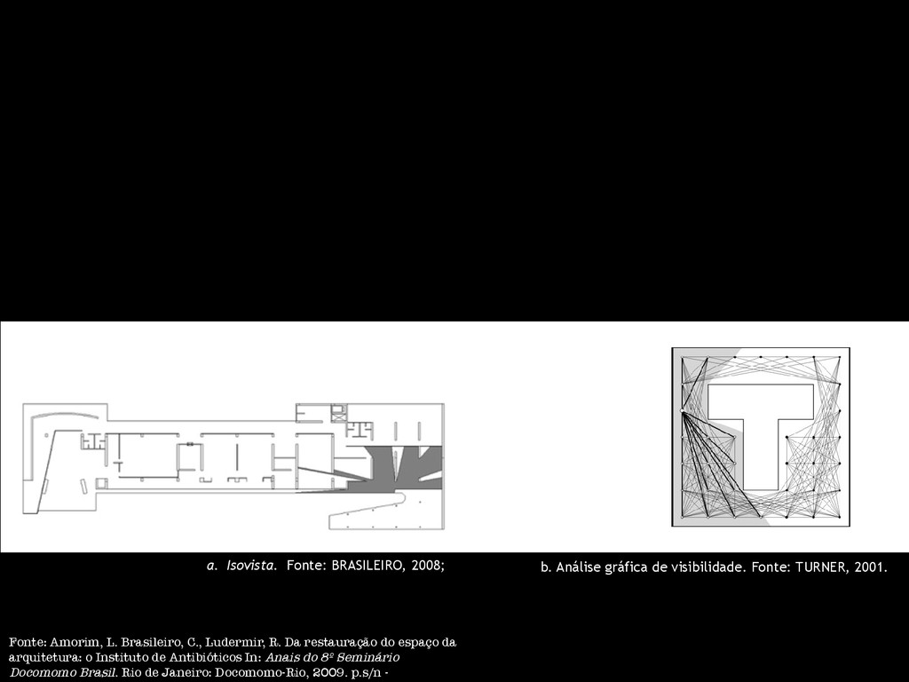
Fonte: TURNER, 2001. Fonte: Amorim, L. Brasileiro, C., Ludermir, R. Da restauração do espaço da arquitetura: o Instituto de Antibióticos In: Anais do 8º Seminário Docomomo Brasil. Rio de Janeiro: Docomomo-Rio, 2009. p.s/n -
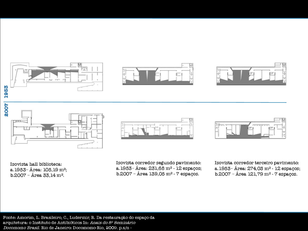
33,14 mƱ. Isovista corredor segundo pavimento: a. 1953– Área: 231,68 mƱ - 12 espaços; b. 2007 – Área 139,05 mƱ - 7 espaços. Isovista corredor terceiro pavimento: a. 1953– Área: 274,03 mƱ - 12 espaços; b. 2007 – Área 121,79 mƱ - 7 espaços. 1953 2007 Fonte: Amorim, L. Brasileiro, C., Ludermir, R. Da restauração do espaço da arquitetura: o Instituto de Antibióticos In: Anais do 8º Seminário Docomomo Brasil. Rio de Janeiro: Docomomo-Rio, 2009. p.s/n -
a biblioteca em 2007. 1 2 3 4 1 2 3 4 5 6 Fonte: Amorim, L. Brasileiro, C., Ludermir, R. Da restauração do espaço da arquitetura: o Instituto de Antibióticos In: Anais do 8º Seminário Docomomo Brasil. Rio de Janeiro: Docomomo-Rio, 2009. p.s/n -
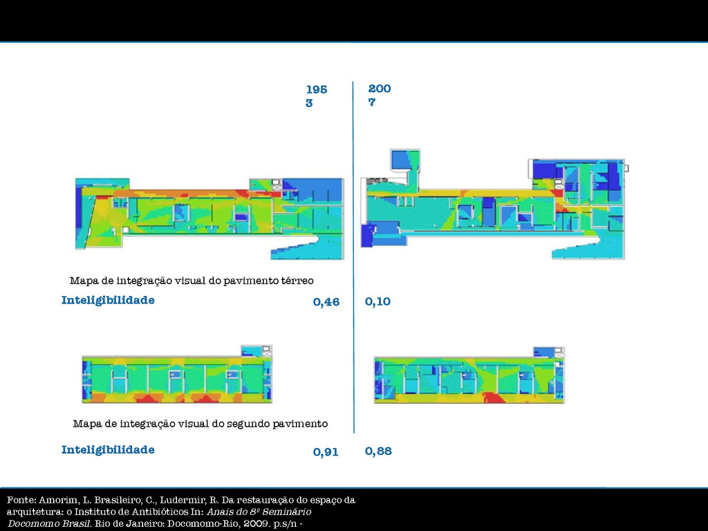
visual do segundo pavimento 195 3 200 7 Inteligibilidade 0,91 0,88 Inteligibilidade 0,46 0,10 Fonte: Amorim, L. Brasileiro, C., Ludermir, R. Da restauração do espaço da arquitetura: o Instituto de Antibióticos In: Anais do 8º Seminário Docomomo Brasil. Rio de Janeiro: Docomomo-Rio, 2009. p.s/n -
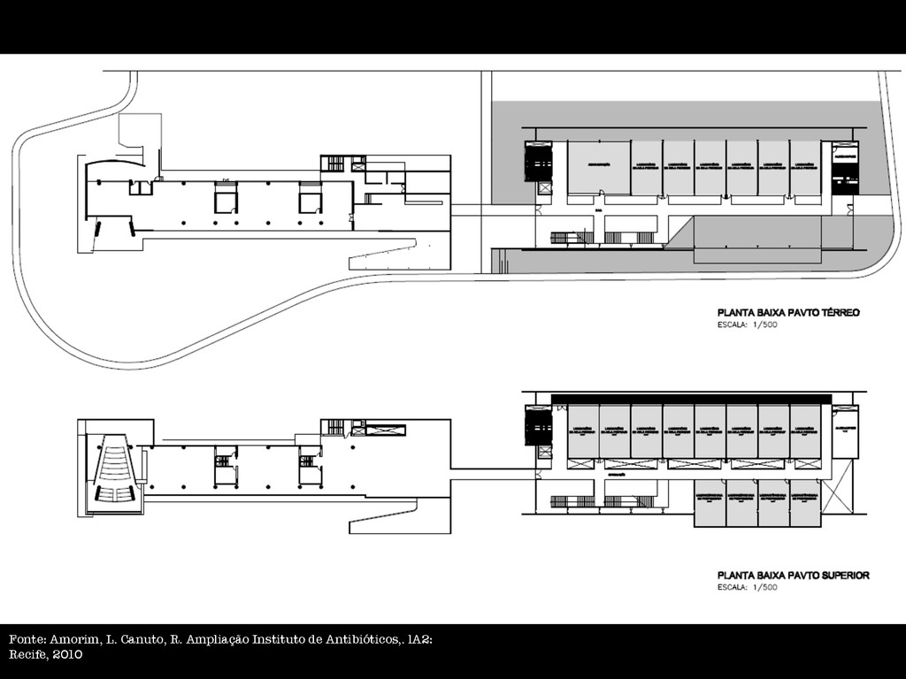
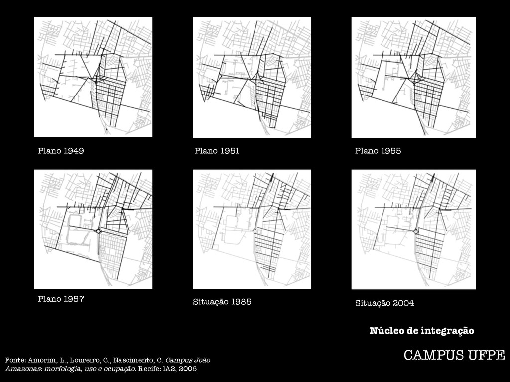
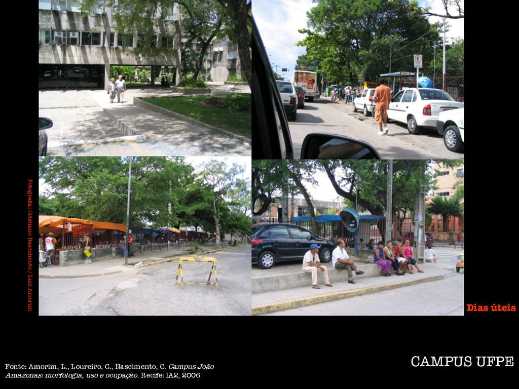
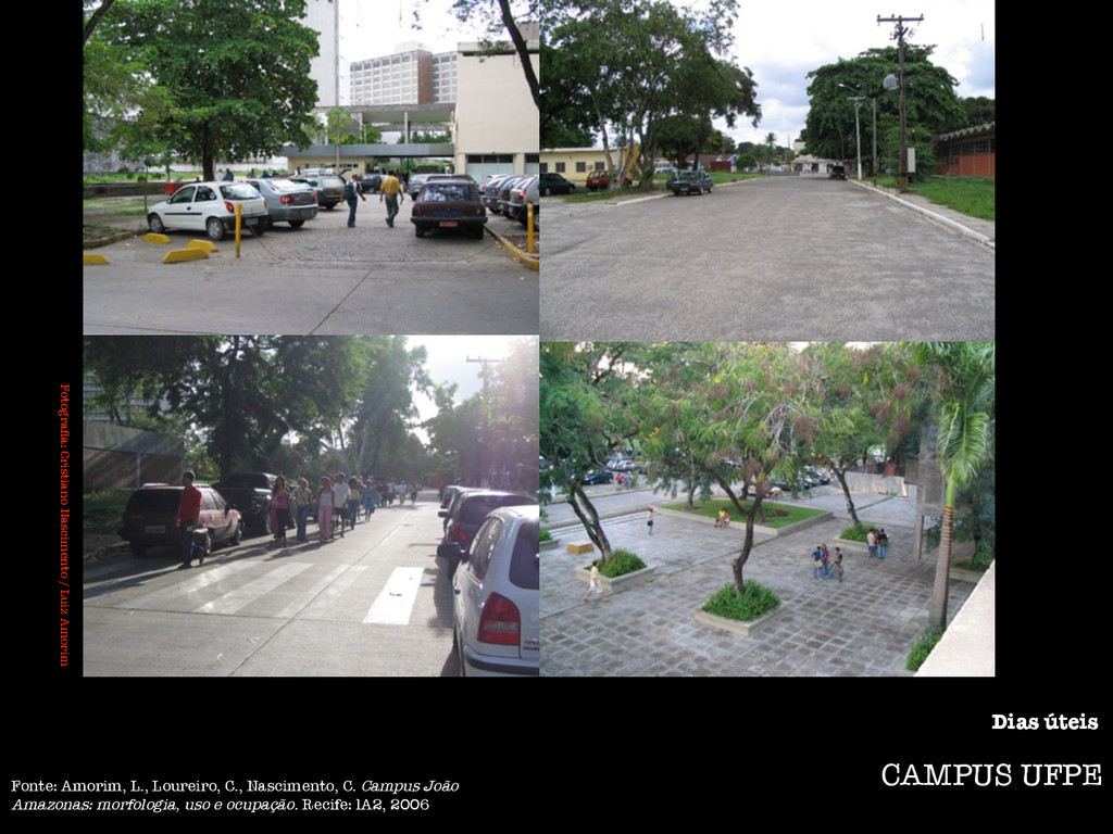
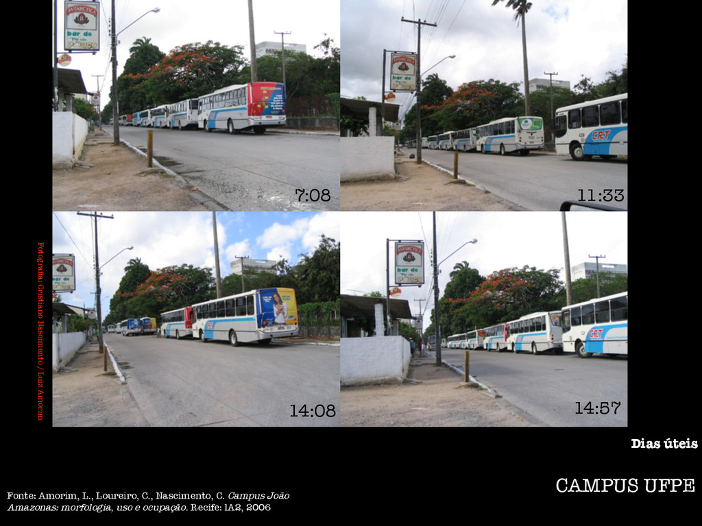
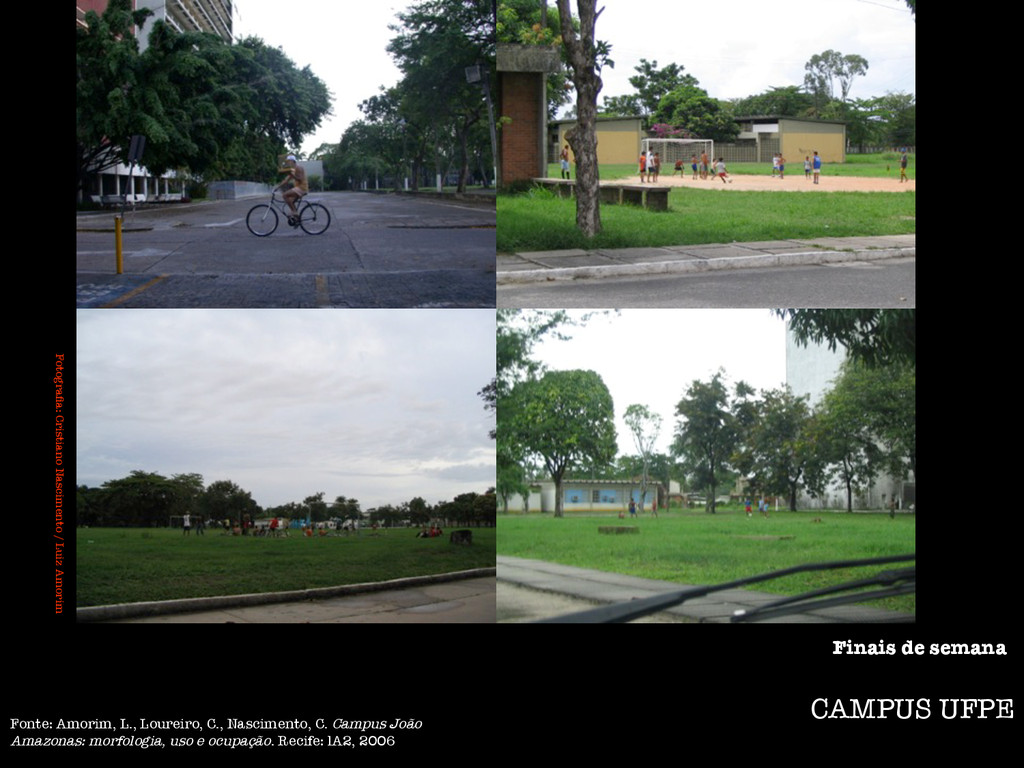
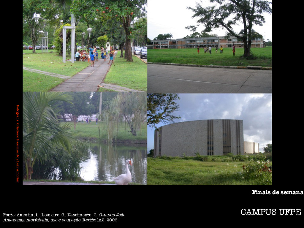
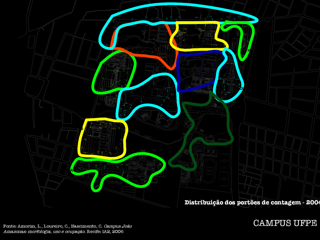
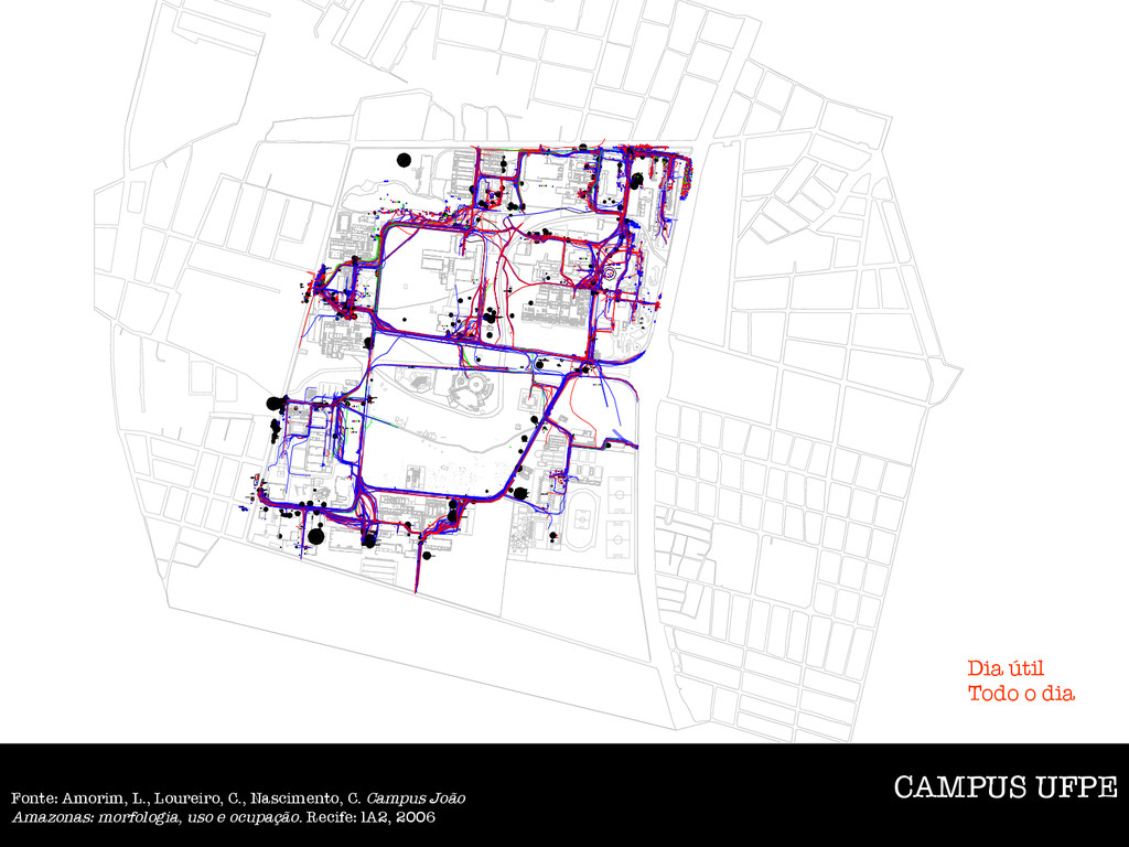
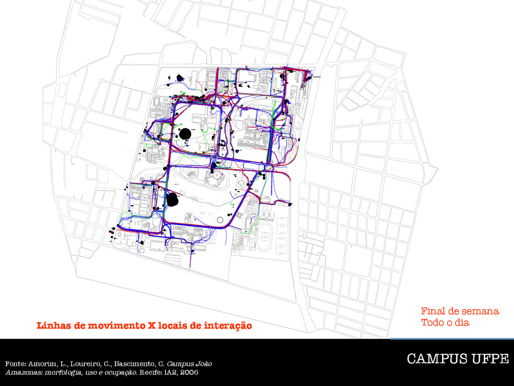
Situação 2004 Núcleo de integração CAMPUS UFPE Fonte: Amorim, L., Loureiro, C., Nascimento, C. Campus João Amazonas: morfologia, uso e ocupação. Recife: lA2, 2006