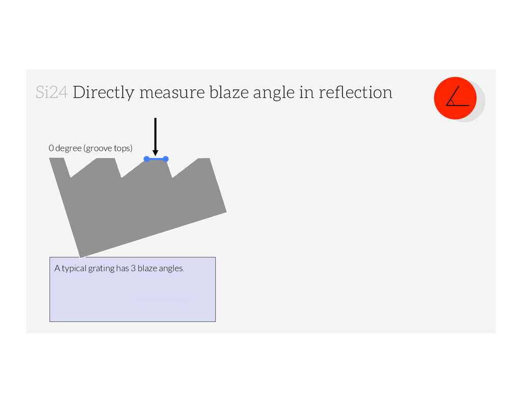
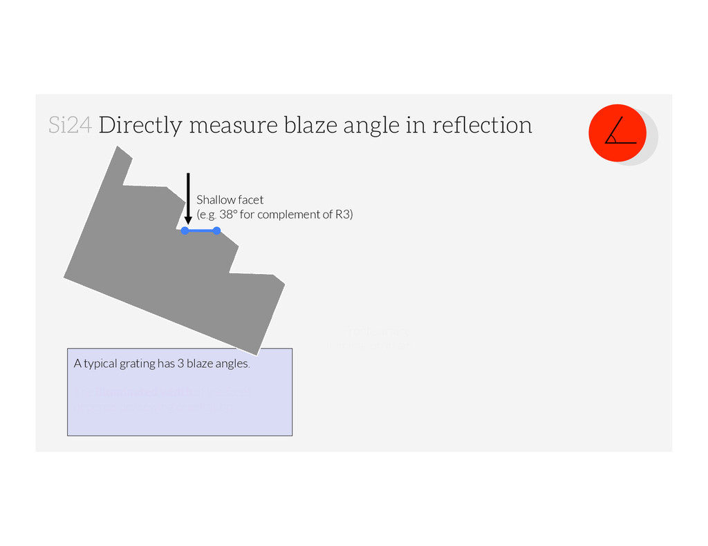
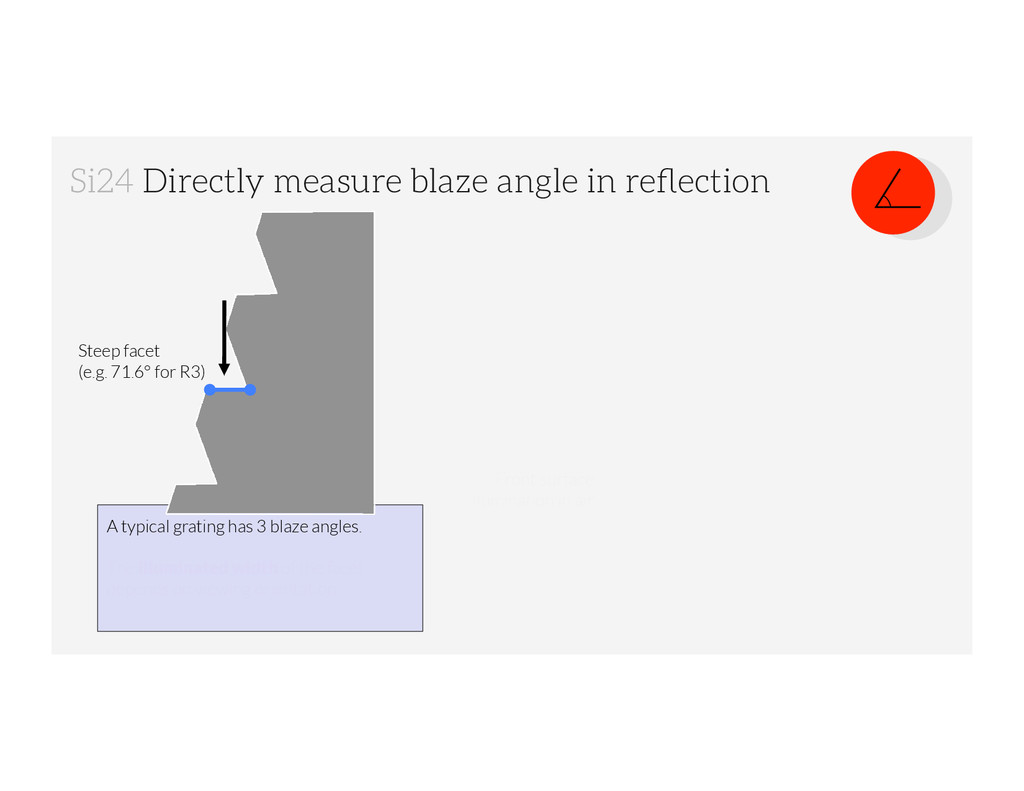
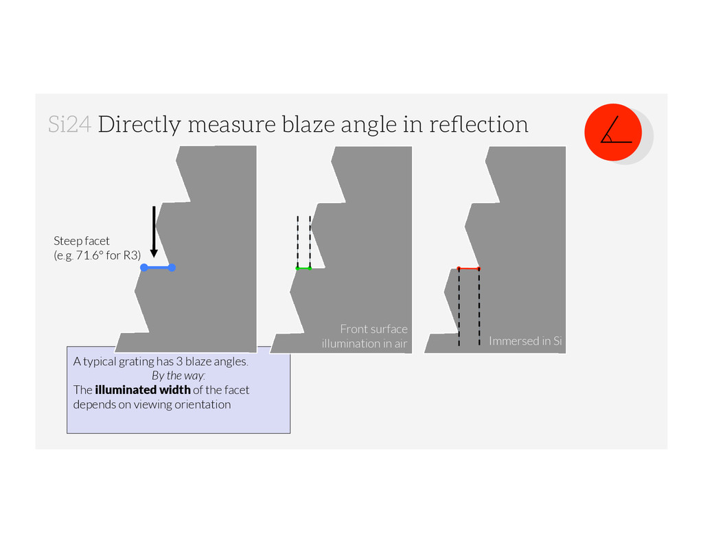
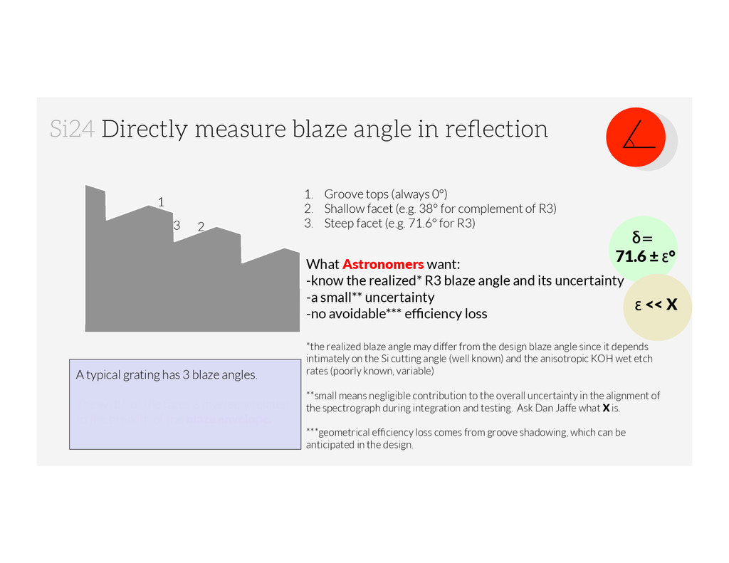
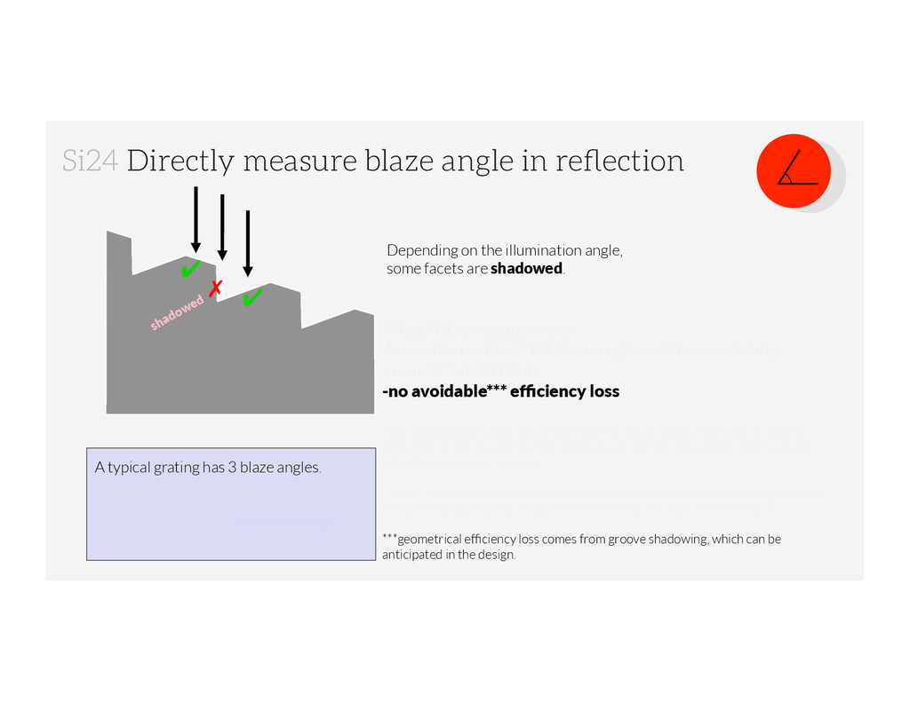
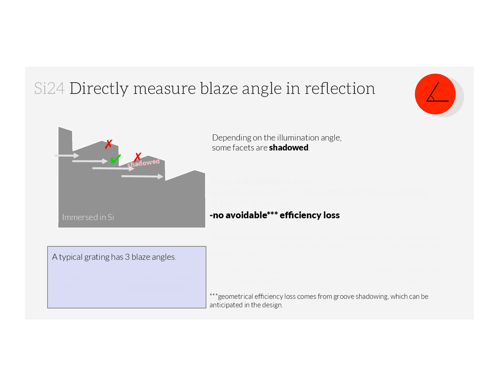
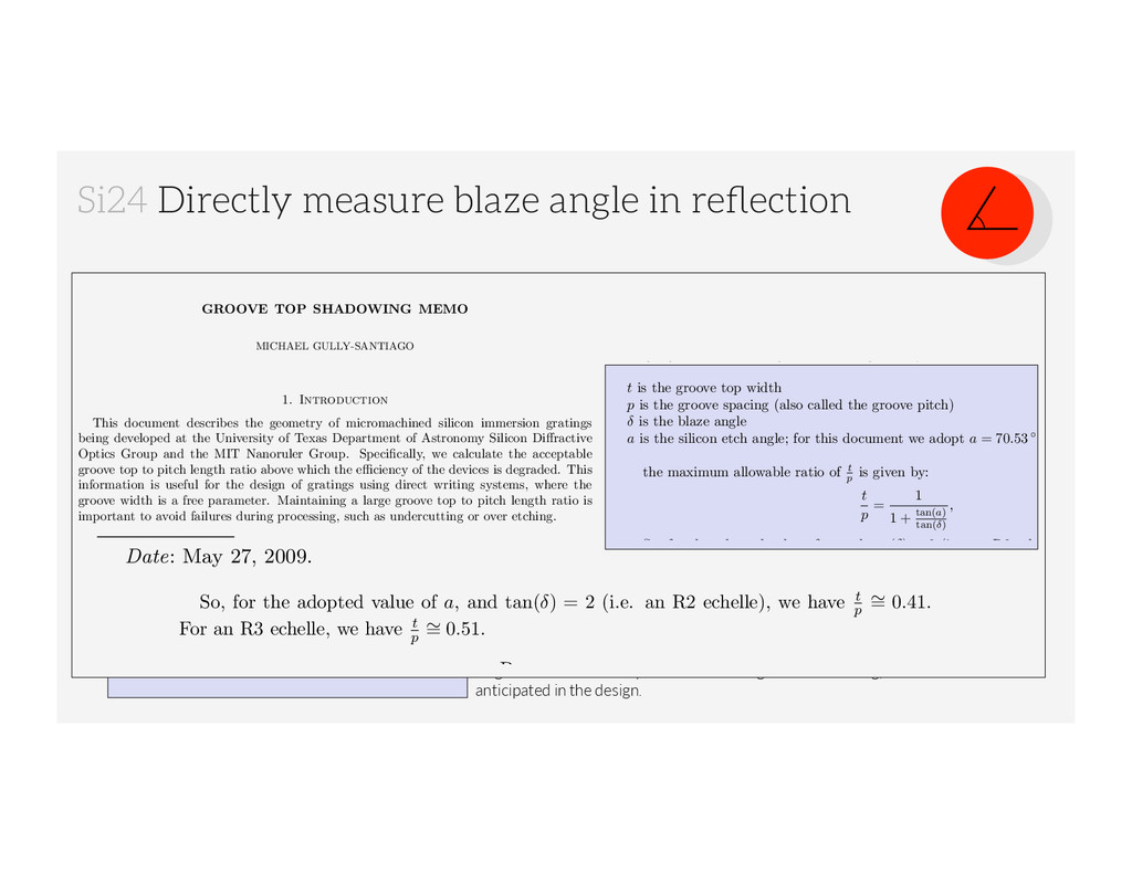
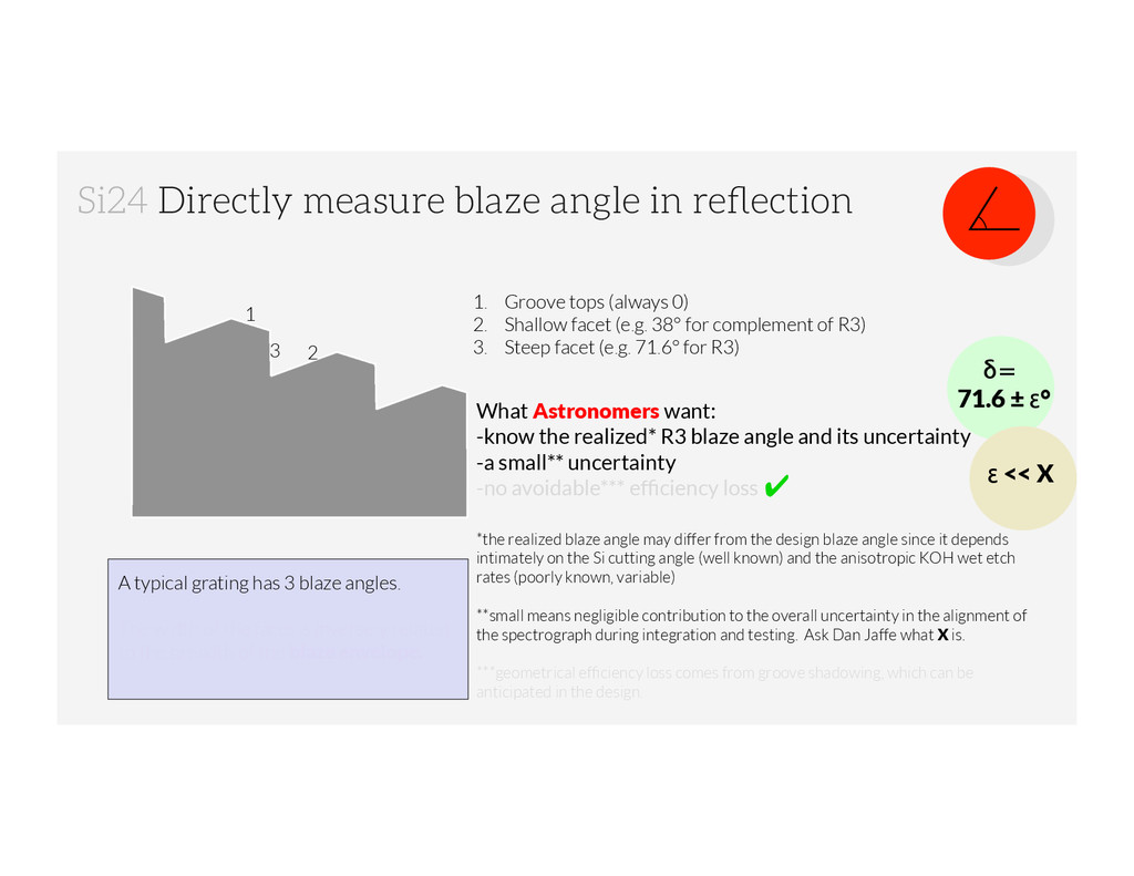
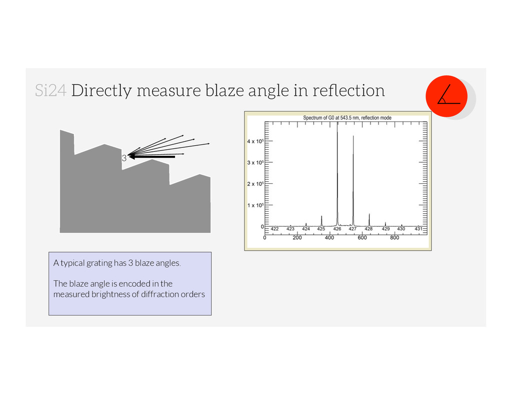
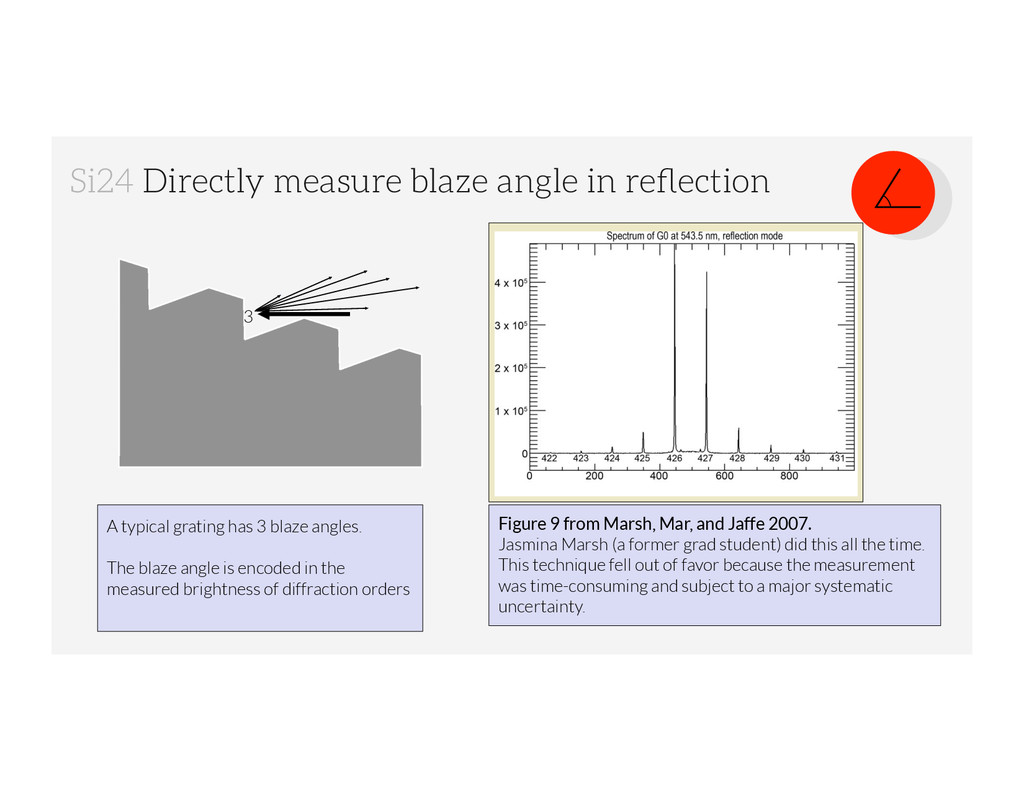
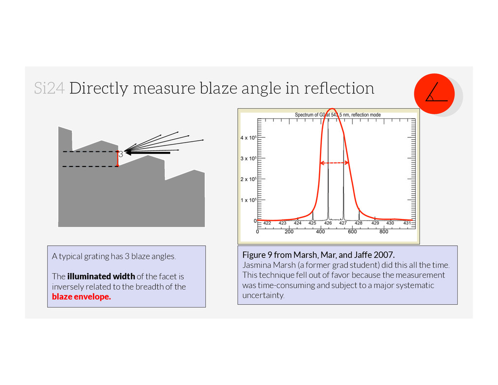
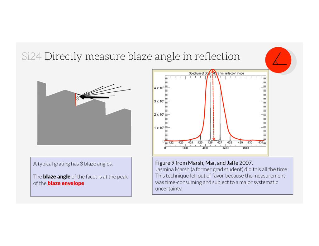
has 3 blaze angles. The width of the facet is inversely related to the breadth of the blaze envelope. Depending on the illumination angle, some facets are shadowed. shadowed ✔ ✗ What Astronomers want: -know the realized* R3 blaze angle and its uncertainty -a small** uncertainty -no avoidable*** efficiency loss *the realized blaze angle may differ from the design blaze angle since it depends intimately on the Si cutting angle (well known) and the anisotropic KOH wet etch rates (poorly known, variable) **small means negligible contribution to the overall uncertainty in the alignment of the spectrograph during integration and testing. Ask Dan Jaffe what X is. ***geometrical efficiency loss comes from groove shadowing, which can be anticipated in the design. ✗ Immersed in Si GROOVE TOP SHADOWING MEMO MICHAEL GULLY-SANTIAGO 1. Introduction This document describes the geometry of micromachined silicon immersion gratings being developed at the University of Texas Department of Astronomy Silicon Diffractive Optics Group and the MIT Nanoruler Group. Specifically, we calculate the acceptable groove top to pitch length ratio above which the efficiency of the devices is degraded. This information is useful for the design of gratings using direct writing systems, where the groove width is a free parameter. Maintaining a large groove top to pitch length ratio is important to avoid failures during processing, such as undercutting or over etching. 2. Geometry Figure 1 shows an overview of a silicon immersion grating. Figure 2 shows a detail of a single groove, chronicling the relevant geometry; the parameters are listed below. t is the groove top width p is the groove spacing (also called the groove pitch) δ is the blaze angle a is the silicon etch angle; for this document we adopt a = 70.53 ◦ , the maximum allowable ratio of t p is given by: t p = 1 1 + tan(a) tan(δ) , So, for the adopted value of a, and tan(δ) = 2 (i.e. an R2 echelle), we have t p ∼ = 0.41. For an R3 echelle, we have t p ∼ = 0.51. References [Marsh et al.(2007)] Marsh, J. P., Mar, D. J., & Jaffe, D. T. 2007, Applied Optics, 46, 3400 MICHAEL GULLY-SANTIAGO 1. Introduction This document describes the geometry of micromachined silicon immersion gratings being developed at the University of Texas Department of Astronomy Silicon Diffractive Optics Group and the MIT Nanoruler Group. Specifically, we calculate the acceptable groove top to pitch length ratio above which the efficiency of the devices is degraded. This information is useful for the design of gratings using direct writing systems, where the groove width is a free parameter. Maintaining a large groove top to pitch length ratio is important to avoid failures during processing, such as undercutting or over etching. 2. Geometry Figure 1 shows an overview of a silicon immersion grating. Figure 2 shows a detail of a single groove, chronicling the relevant geometry; the parameters are listed below. t is the groove top width p is the groove spacing (also called the groove pitch) δ is the blaze angle a is the silicon etch angle; for this document we adopt a = 70.53 ◦ , the maximum allowable ratio of t p is given by: t p = 1 1 + tan(a) tan(δ) , So, for the adopted value of a, and tan(δ) = 2 (i.e. an R2 echelle), we have t p ∼ = 0.41. For an R3 echelle, we have t p ∼ = 0.51. References [Marsh et al.(2007)] Marsh, J. P., Mar, D. J., & Jaffe, D. T. 2007, Applied Optics, 46, 3400 Date: May 27, 2009. 1 δ is the blaze angle a is the silicon etch angle; for this document we adopt a = 70.53 ◦ , the maximum allowable ratio of t p is given by: t p = 1 1 + tan(a) tan(δ) , So, for the adopted value of a, and tan(δ) = 2 (i.e. an R2 echelle), we have t p ∼ = 0.41. For an R3 echelle, we have t p ∼ = 0.51. References [Marsh et al.(2007)] Marsh, J. P., Mar, D. J., & Jaffe, D. T. 2007, Applied Optics, 46, 3400 Date: May 27, 2009. 1 GROOVE TOP SHADOWING MEMO MICHAEL GULLY-SANTIAGO 1. Introduction This document describes the geometry of micromachined silicon immersion being developed at the University of Texas Department of Astronomy Silicon Di Optics Group and the MIT Nanoruler Group. Specifically, we calculate the ac groove top to pitch length ratio above which the efficiency of the devices is degrad information is useful for the design of gratings using direct writing systems, w groove width is a free parameter. Maintaining a large groove top to pitch length important to avoid failures during processing, such as undercutting or over etchin 2. Geometry Figure 1 shows an overview of a silicon immersion grating. Figure 2 shows a de single groove, chronicling the relevant geometry; the parameters are listed below. t is the groove top width p is the groove spacing (also called the groove pitch) δ is the blaze angle a is the silicon etch angle; for this document we adopt a = 70.53 ◦ , the maximum allowable ratio of t p is given by: t p = 1 1 + tan(a) tan(δ) , So, for the adopted value of a, and tan(δ) = 2 (i.e. an R2 echelle), we have t p For an R3 echelle, we have t p ∼ = 0.51. References [Marsh et al.(2007)] Marsh, J. P., Mar, D. J., & Jaffe, D. T. 2007, Applied Optics, 46, 3400 Date: May 27, 2009. 1
![[email protected] | astronomer and engineer attribution to: les vieux garçons,](https://files.speakerdeck.com/presentations/a4e6255084bb01328fc62e7b8af14da2/slide_54.jpg)