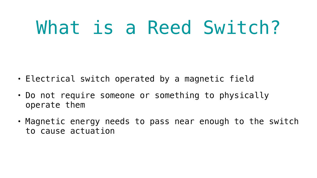
a magnetic field • Do not require someone or something to physically operate them • Magnetic energy needs to pass near enough to the switch to cause actuation
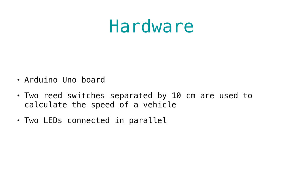
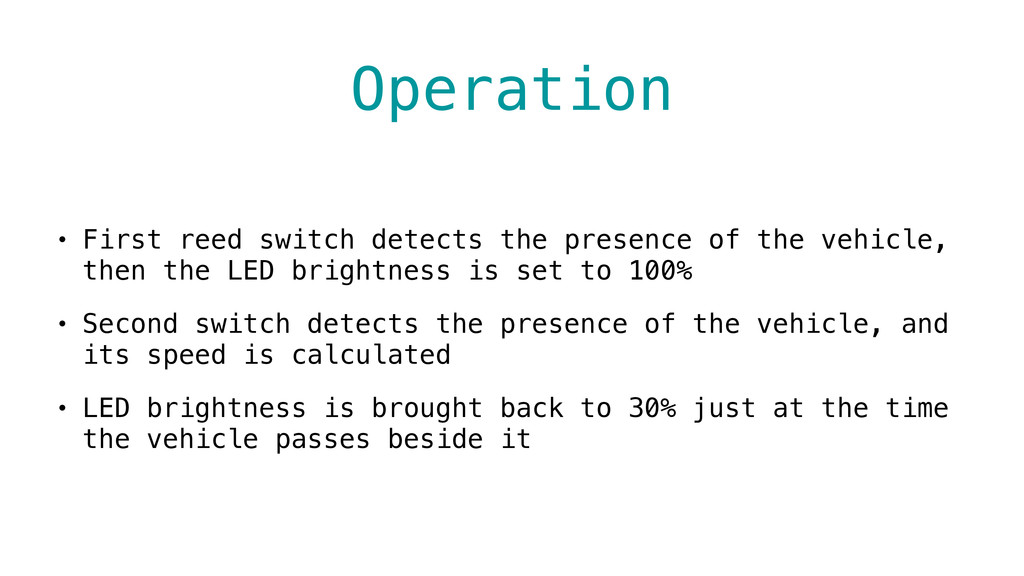
vehicle, then the LED brightness is set to 100% • Second switch detects the presence of the vehicle, and its speed is calculated • LED brightness is brought back to 30% just at the time the vehicle passes beside it
the LED is attached to const int switchAPin = 2; // the pin that the reed switch A is attached to const int switchBPin = 3; // the pin that the reed switch B is attached to const byte partialBrightness = 77; // 30% of brightness based in a 0 to 255 scale const byte fullBrightness = 255; // 100% of brightness based in a 0 to 255 scale const float distance = 0.10; // distance between reed switches (10 cm) int switchAReading; int switchBReading; unsigned long switchATime; unsigned long switchBTime; void setup() { // initialize the LED pin as an output: pinMode(ledPin, OUTPUT); analogWrite(ledPin, partialBrightness); // set LED brightness to 30% // initialize the reed switches pins as inputs: pinMode(switchAPin, INPUT); pinMode(switchBPin, INPUT); }
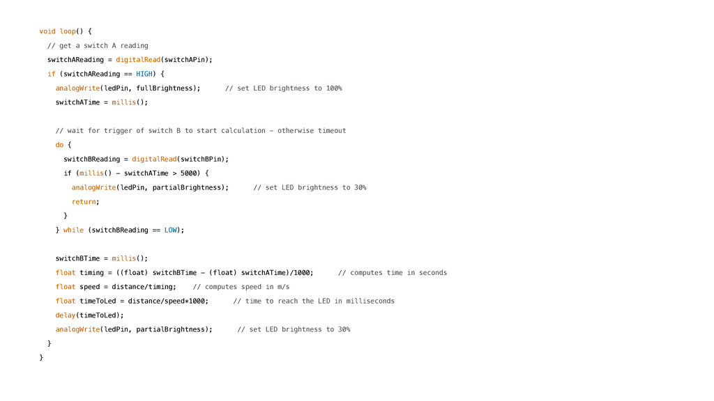
= digitalRead(switchAPin); if (switchAReading == HIGH) { analogWrite(ledPin, fullBrightness); // set LED brightness to 100% switchATime = millis(); // wait for trigger of switch B to start calculation - otherwise timeout do { switchBReading = digitalRead(switchBPin); if (millis() - switchATime > 5000) { analogWrite(ledPin, partialBrightness); // set LED brightness to 30% return; } } while (switchBReading == LOW); switchBTime = millis(); float timing = ((float) switchBTime - (float) switchATime)/1000; // computes time in seconds float speed = distance/timing; // computes speed in m/s float timeToLed = distance/speed*1000; // time to reach the LED in milliseconds delay(timeToLed); analogWrite(ledPin, partialBrightness); // set LED brightness to 30% } }
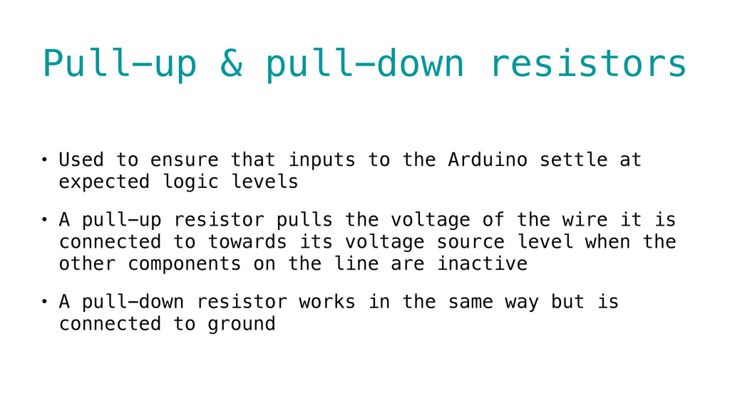
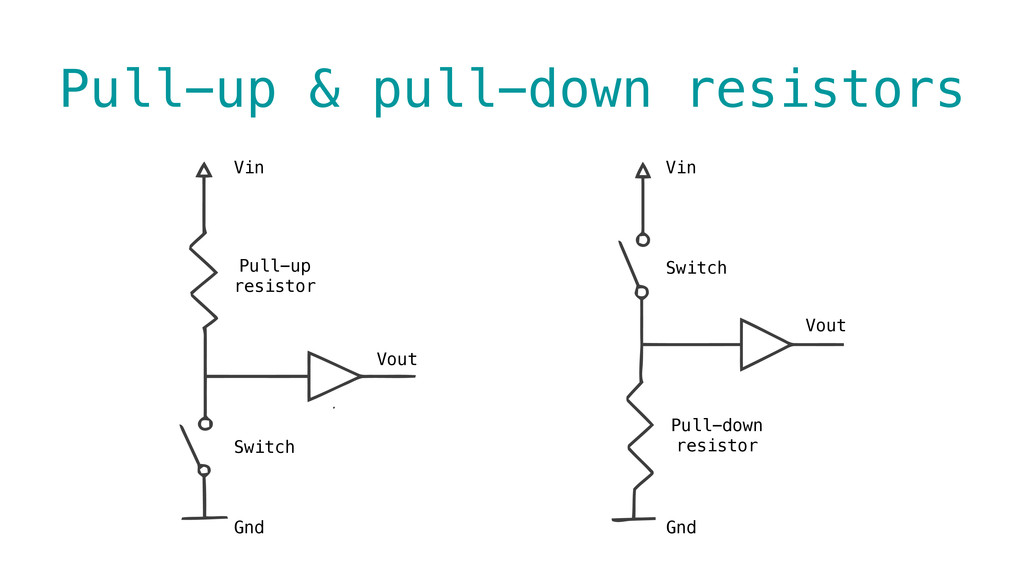
to the Arduino settle at expected logic levels • A pull-up resistor pulls the voltage of the wire it is connected to towards its voltage source level when the other components on the line are inactive • A pull-down resistor works in the same way but is connected to ground