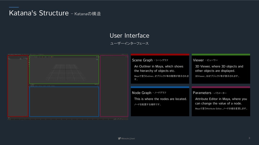
Graph - シーングラフ An Outliner in Maya, which shows the hierarchy of objects etc. Mayaで言うOutliner。オブジェクト等の階層が表示されま す。 Viewer - ビューワー 3D Viewer, where 3D objects and other objects are displayed. 3DViewer。3Dオブジェクト等が表示されます。 Node Graph - ノードグラフ This is where the nodes are located. ノードを配置する場所です。 Parameters - パラメーター Attribute Editor in Maya, where you can change the value of a node. Mayaで言うAttribute Editor。ノードの値を変更します。
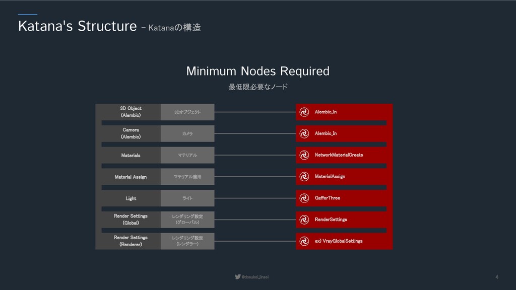
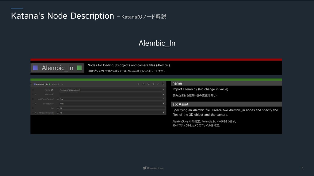
(値の変更は無し) Import Hierarchy (No change in value) abcAsset Alembicファイルの指定。「Alembic_In」ノードを2つ作り、 3Dオブジェクトとカメラのファイルを指定。 Specifying an Alembic file. Create two Alembic_in nodes and specify the files of the 3D object and the camera. 3Dオブジェクトやカメラのファイル(Alembic)を読み込むノードです。 Nodes for loading 3D objects and camera files (Alembic).
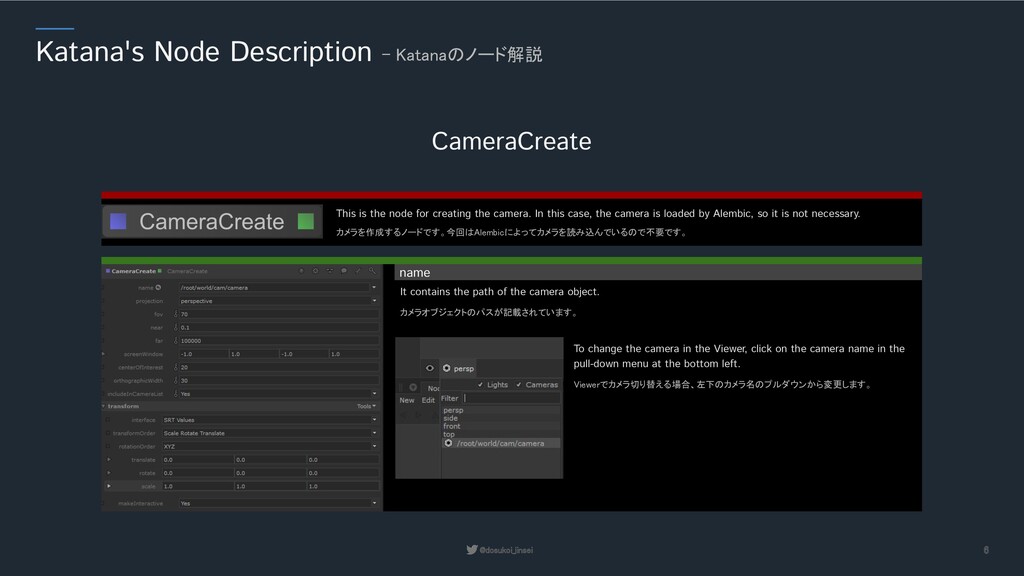
It contains the path of the camera object. カメラを作成するノードです。今回はAlembicによってカメラを読み込んでいるので不要です。 This is the node for creating the camera. In this case, the camera is loaded by Alembic, so it is not necessary. Viewerでカメラ切り替える場合、左下のカメラ名のプルダウンから変更します。 To change the camera in the Viewer, click on the camera name in the pull-down menu at the bottom left.
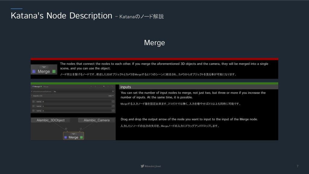
You can set the number of input nodes to merge, not just two, but three or more if you increase the number of inputs. At the same time, it is possible. ノード同士を繋げるノードです。前述した3DオブジェクトとカメラをMergeすると1つのシーンに統合され、カメラからオブジェクトを見る事が可能になります。 The nodes that connect the nodes to each other. If you merge the aforementioned 3D objects and the camera, they will be merged into a single scene, and you can use the object. 入力したいノードの出力の矢印を、Mergeノードの入力にドラッグアンドドロップします。 Drag and drop the output arrow of the node you want to input to the input of the Merge node.
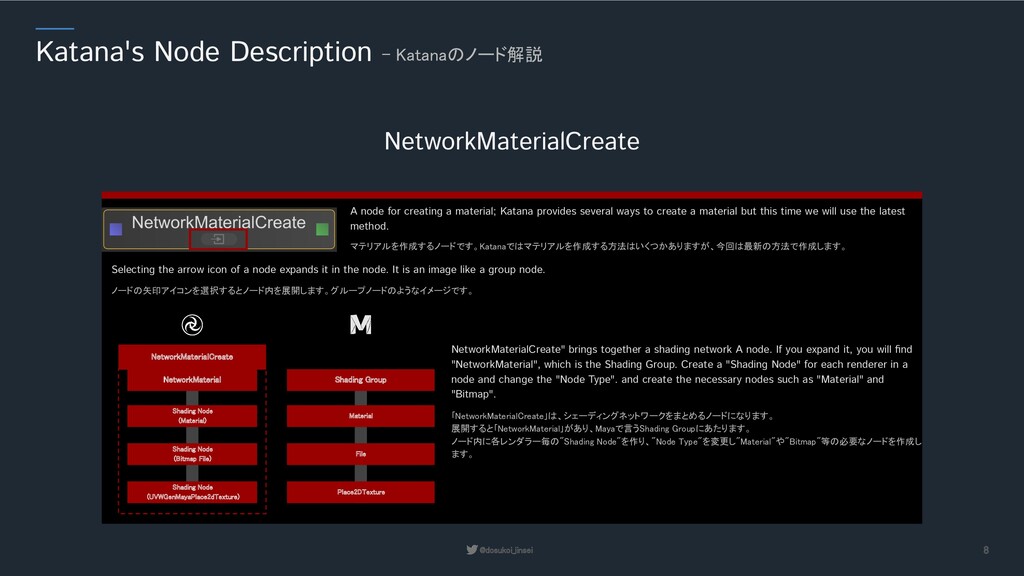
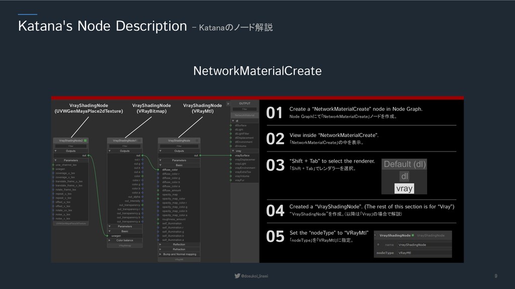
A node for creating a material; Katana provides several ways to create a material but this time we will use the latest method. ノードの矢印アイコンを選択するとノード内を展開します。グループノードのようなイメージです。 Selecting the arrow icon of a node expands it in the node. It is an image like a group node. Shading Node (Material) Shading Node (Bitmap File) Shading Node (UVWGenMayaPlace2dTexture) NetworkMaterialCreate Material File Place2DTexture Shading Group 「NetworkMaterialCreate」は、シェーディングネットワークをまとめるノードになります。 展開すると「NetworkMaterial」があり、Mayaで言うShading Groupにあたります。 ノード内に各レンダラー毎の"Shading Node"を作り、"Node Type"を変更し"Material"や"Bitmap"等の必要なノードを作成し ます。 NetworkMaterialCreate" brings together a shading network A node. If you expand it, you will find "NetworkMaterial", which is the Shading Group. Create a "Shading Node" for each renderer in a node and change the "Node Type". and create the necessary nodes such as "Material" and "Bitmap". NetworkMaterial
VrayShadingNode (VRayBitmap) VrayShadingNode (UVWGenMayaPlace2dTexture) 01 Create a “NetworkMaterialCreate” node in Node Graph. Node Graphにて「NetworkMaterialCreate」ノードを作成。 03 “Shift + Tab” to select the renderer. 「Shift + Tab」でレンダラーを選択。 02 View inside “NetworkMaterialCreate”. 「NetworkMaterialCreate」の中を表示。 04 Created a “VrayShadingNode”. (The rest of this section is for “Vray”) “VrayShadingNode”を作成。(以降は「Vray」の場合で解説) 05 Set the “nodeType” to “VRayMtl” 「nodeType」を「VRayMtl」に指定。
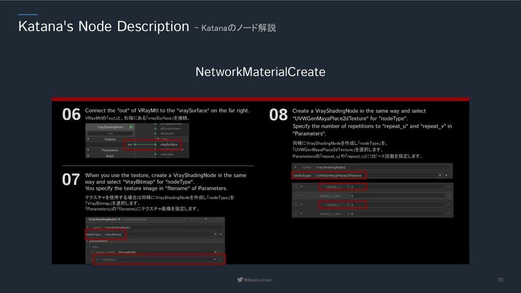
the "out" of VRayMtl to the "vraySurface" on the far right. VRayMtlの「out」と、右端にある「vraySurface」を接続。 07 When you use the texture, create a VrayShadingNode in the same way and select "VrayBitmap" for "nodeType". You specify the texture image in "filename" of Parameters. テクスチャを使用する場合は同様にVrayShadingNodeを作成し「nodeType」を 「VrayBitmap」を選択します。 「Parameters」の「filename」にテクスチャ画像を指定します。 08 Create a VrayShadingNode in the same way and select "UVWGenMayaPlace2dTexture" for "nodeType". Specify the number of repetitions to "repeat_u" and "repeat_v" in "Parameters". 同様にVrayShadingNodeを作成し「nodeType」を、 「UVWGenMayaPlace2dTexture」を選択します。 Parametersの「repeat_u」や「repeat_v」にリピート回数を指定します。
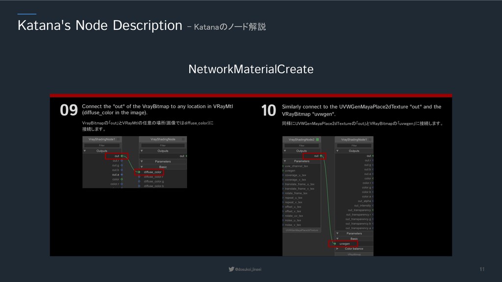
the "out" of the VrayBitmap to any location in VRayMtl (diffuse_color in the image). VrayBitmapの「out」とVRayMtlの任意の場所(画像ではdiffuse_color)に 接続します。 10 Similarly connect to the UVWGenMayaPlace2dTexture "out" and the VRayBitmap "uvwgen". 同様にUVWGenMayaPlace2dTextureの「out」とVRayBitmapの「uvwgen」に接続します。
some things to keep in mind when moving from Maya (Vray) to Katana (Vray). There are some parameters that are enabled by default in Maya but not in Katana, so we will explain them here. Maya(Vray)からKatana(Vray)に移行する際に注意点があります。 Mayaではデフォルトで有効になっていてKatanaでは有効になっていないパラメーター等がありますので、ここではそれを解説していきます。 Maya and Katana Compatibility (Vray) - MayaとKatanaの互換性(Vray) Material - Refraction Affect Shadows "Affect Shadows" accurately renders the shadows cast by transparent objects. It is not enabled by default in Katana, so it is recommended that you enable it. "Affect Shadows"は透明なオブジェクトが落とす影を正確に描画します。 Katanaではデフォルトで有効化されていないので、必ず有効化するのを推奨しま す。
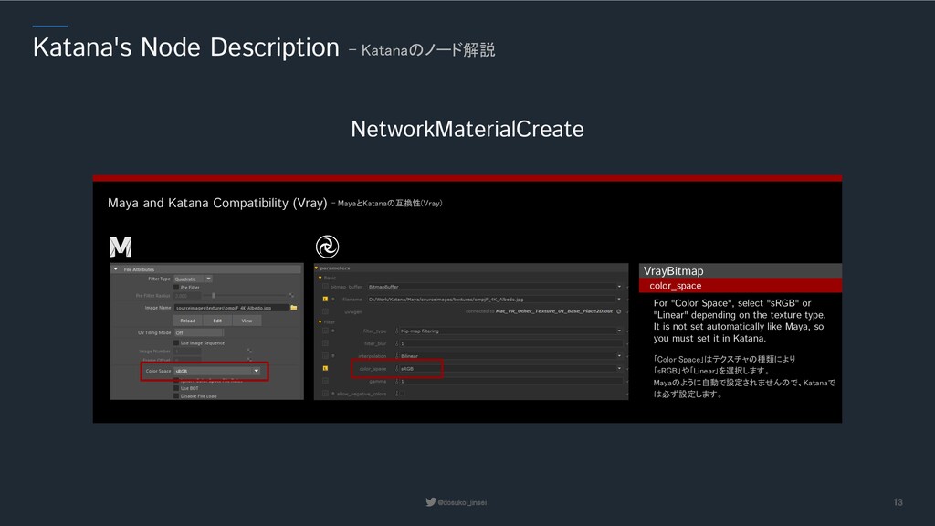
Katana Compatibility (Vray) - MayaとKatanaの互換性(Vray) VrayBitmap color_space For "Color Space", select "sRGB" or "Linear" depending on the texture type. It is not set automatically like Maya, so you must set it in Katana. 「Color Space」はテクスチャの種類により 「sRGB」や「Linear」を選択します。 Mayaのように自動で設定されませんので、Katanaで は必ず設定します。
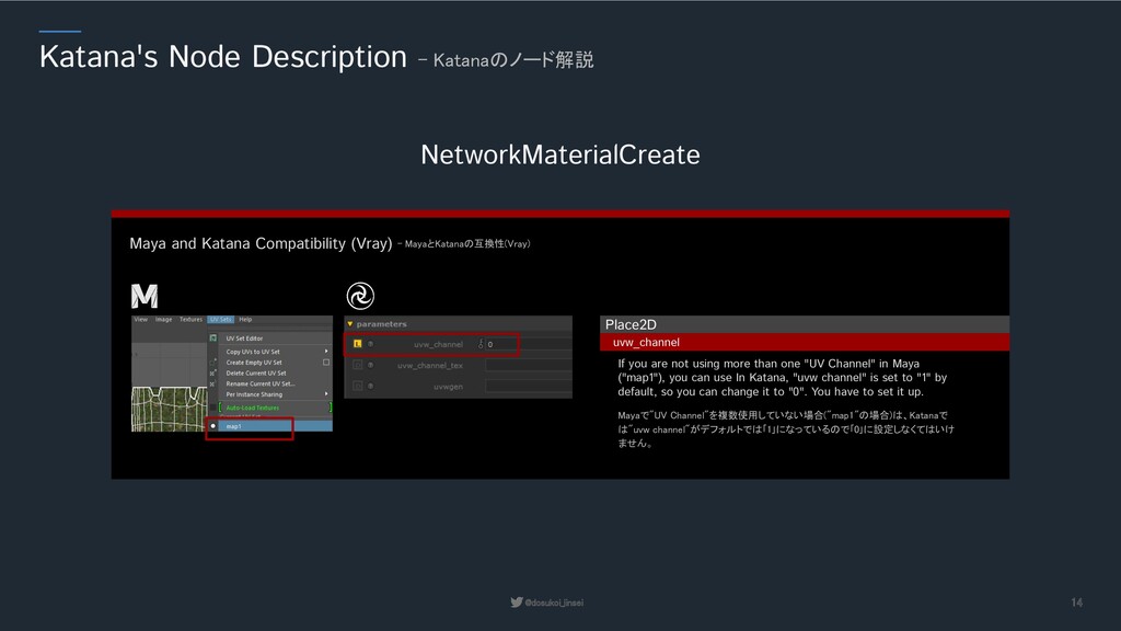
Katana Compatibility (Vray) - MayaとKatanaの互換性(Vray) Place2D uvw_channel If you are not using more than one "UV Channel" in Maya ("map1"), you can use In Katana, "uvw channel" is set to "1" by default, so you can change it to "0". You have to set it up. Mayaで"UV Channel"を複数使用していない場合("map1"の場合)は、Katanaで は"uvw channel"がデフォルトでは「1」になっているので「0」に設定しなくてはいけ ません。
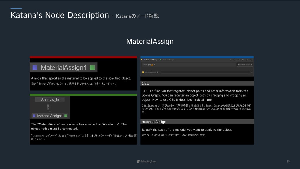
Graphから任意のオブジェクトをド ラッグアンドドロップする事でオブジェクトパスを登録出来ます。CELの詳細は使用方法は後述しま す。 CEL is a function that registers object paths and other information from the Scene Graph. You can register an object path by dragging and dropping an object. How to use CEL is described in detail later. 指定されたオブジェクトに対して、適用するマテリアルを指定するノードです。 A node that specifies the material to be applied to the specified object. "MaterialAssign"ノードには必ず"Alembic_In"のようにオブジェクトノードが接続されている必要 があります。 The "MaterialAssign" node always has a value like "Alembic_In". The object nodes must be connected. materialAssign Specify the path of the material you want to apply to the object. オブジェクトに適用したいマテリアルのパスを指定します。
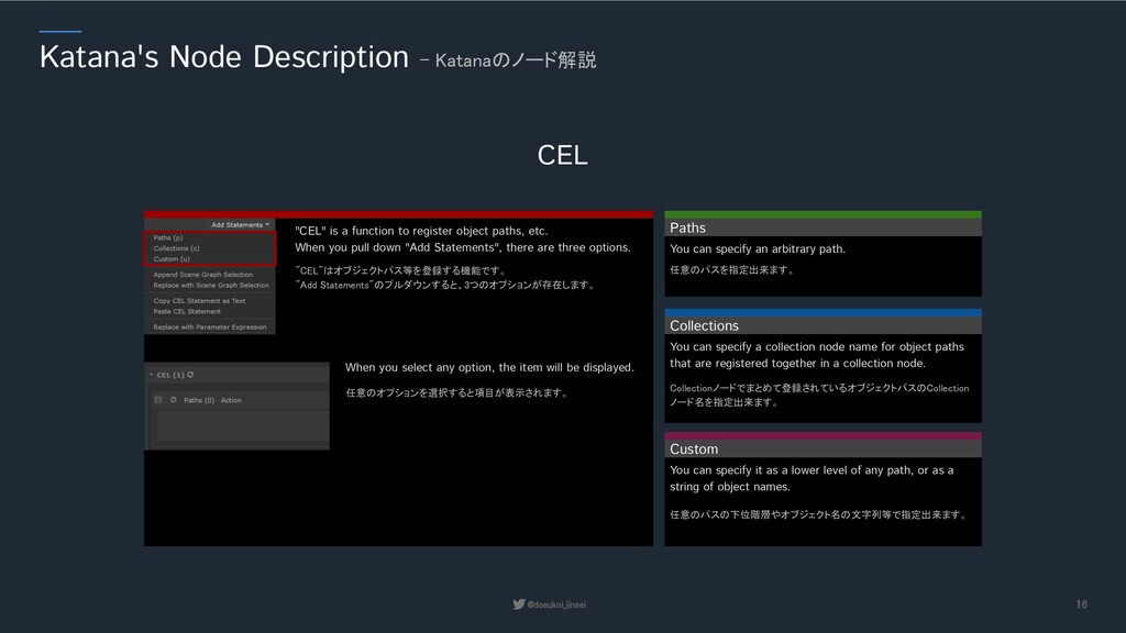
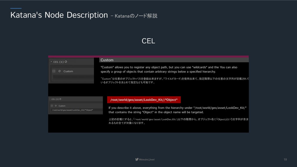
"CEL" is a function to register object paths, etc. When you pull down "Add Statements", there are three options. When you select any option, the item will be displayed. "CEL"はオブジェクトパス等を登録する機能です。 "Add Statements"のプルダウンすると、3つのオプションが存在します。 Paths You can specify an arbitrary path. 任意のパスを指定出来ます。 Collections You can specify a collection node name for object paths that are registered together in a collection node. Collectionノードでまとめて登録されているオブジェクトパスのCollection ノード名を指定出来ます。 Custom You can specify it as a lower level of any path, or as a string of object names. 任意のパスの下位階層やオブジェクト名の文字列等で指定出来ます。
オブジェクト個別に指定も可能ですが、グループを指定した場合は下層のオブジェクト全てに適用します。 "Paths" allows you to register an arbitrary object path by dragging and dropping it. You can specify an individual object, but if you specify a group, it will be applied to all the underlying objects. Paths
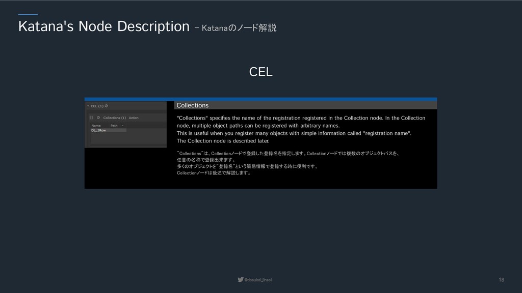
任意の名称で登録出来ます。 多くのオブジェクトを"登録名"という簡易情報で登録する時に便利です。 Collectionノードは後述で解説します。 "Collections" specifies the name of the registration registered in the Collection node. In the Collection node, multiple object paths can be registered with arbitrary names. This is useful when you register many objects with simple information called "registration name". The Collection node is described later. Collections
"Custom" allows you to register any object path, but you can use "wildcards" and the You can also specify a group of objects that contain arbitrary strings below a specified hierarchy. Custom /root/world/geo/asset/LookDev_Kit//*Object* 上記の記載にすると、「/root/world/geo/asset/LookDev_Kit/」以下の階層から、オブジェクト名に「Object」という文字列が含ま れるもの全てが対象になります。 If you describe it above, everything from the hierarchy under "/root/world/geo/asset/LookDev_Kit/" that contains the string "Object" in the object name will be targeted.
2個目以降は、1個目に対してどのような挙動をするか指定出来ます。 挙動は以下の3種類あります。 "CEL" can be added more than one. After the second one, you can specify how it will behave with respect to the first one. There are three types of behavior. Union It is processed by "Union" with the first “CEL”. 1つ目のCELと「合体」して処理します。 Difference The first to second “CEL” is "Difference" from the first. 1つ目から2つ目のCELを「差し引いて」処理します。 Intersect Process the first and second "CEL" by "crossing" them. 1つ目と2つ目のCELを「交差」して処理します。
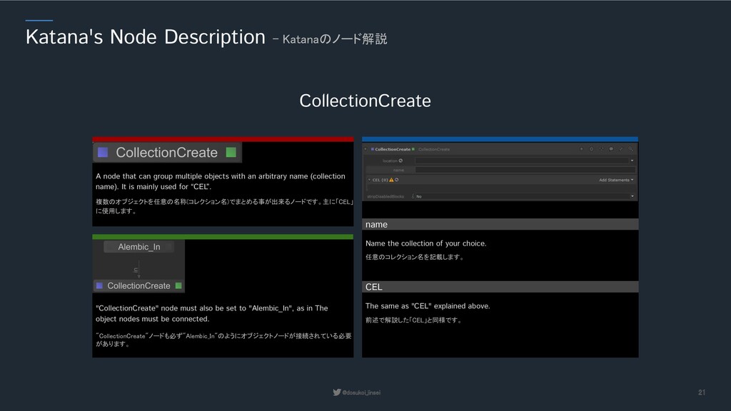
The same as "CEL" explained above. 複数のオブジェクトを任意の名称(コレクション名)でまとめる事が出来るノードです。主に「CEL」 に使用します。 A node that can group multiple objects with an arbitrary name (collection name). It is mainly used for “CEL”. "CollectionCreate"ノードも必ず"Alembic_In"のようにオブジェクトノードが接続されている必要 があります。 "CollectionCreate" node must also be set to "Alembic_In", as in The object nodes must be connected. name Name the collection of your choice. 任意のコレクション名を記載します。
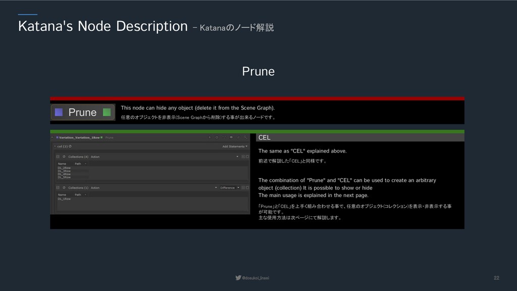
This node can hide any object (delete it from the Scene Graph). CEL 前述で解説した「CEL」と同様です。 The same as "CEL" explained above. 「Prune」と「CEL」を上手く組み合わせる事で、任意のオブジェクト(コレクション)を表示・非表示する事 が可能です。 主な使用方法は次ページにて解説します。 The combination of "Prune" and "CEL" can be used to create an arbitrary object (collection) It is possible to show or hide The main usage is explained in the next page.
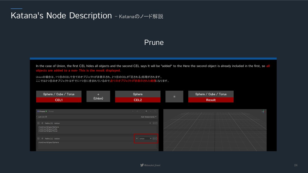
ここでは2つ目のオブジェクトはすでに1つ目に含まれているので、 全てのオブジェクトが非表示された結果 になります。 In the case of Union, the first CEL hides all objects and the second CEL says It will be "added" to the Here the second object is already included in the first, so all objects are added to a non- This is the result displayed. CEL1 + (Union) = Sphere / Cube / Torus CEL2 Sphere Result Sphere / Cube / Torus
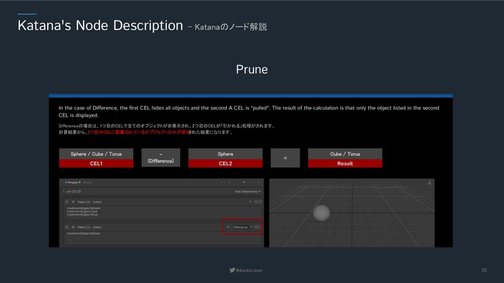
計算結果から、2つ目のCELに記載されているオブジェクトのみが表示 された結果になります。 In the case of Difference, the first CEL hides all objects and the second A CEL is "pulled". The result of the calculation is that only the object listed in the second CEL is displayed. CEL1 - (Difference) = Sphere / Cube / Torus CEL2 Sphere Result Cube / Torus
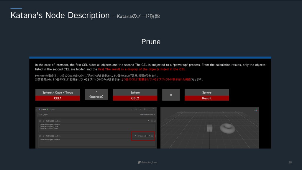
計算結果から、2つ目のCELに記載されているオブジェクトのみが非表示され、 1つ目のCELに記載されているオブジェクトが表示された結果 になります。 In the case of Intersect, the first CEL hides all objects and the second The CEL is subjected to a "power-up" process. From the calculation results, only the objects listed in the second CEL are hidden and the first The result is a display of the objects listed in the CEL. CEL1 ^ (Intersect) = Sphere / Cube / Torus CEL2 Sphere Result Sphere
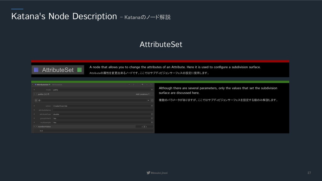
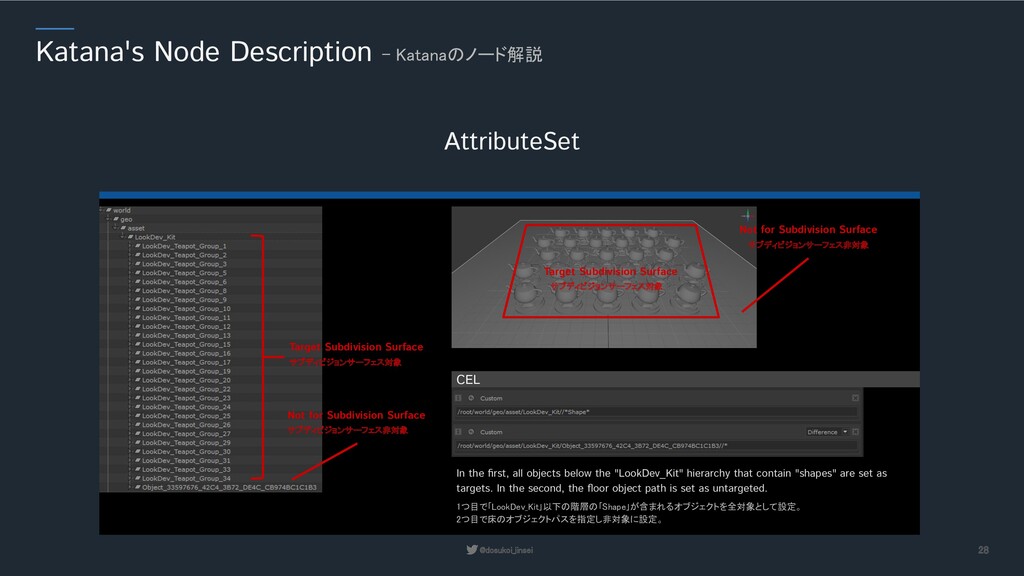
A node that allows you to change the attributes of an Attribute. Here it is used to configure a subdivision surface. 複数のパラメータがありますが、ここではサブディビジョンサーフェスを設定する値のみ解説します。 Although there are several parameters, only the values that set the subdivision surface are discussed here.
Surface Not for Subdivision Surface Target Subdivision Surface Not for Subdivision Surface サブディビジョンサーフェス対象 サブディビジョンサーフェス非対象 サブディビジョンサーフェス対象 サブディビジョンサーフェス非対象 1つ目で「LookDev_Kit」以下の階層の「Shape」が含まれるオブジェクトを全対象として設定。 2つ目で床のオブジェクトパスを指定し非対象に設定。 In the first, all objects below the "LookDev_Kit" hierarchy that contain "shapes" are set as targets. In the second, the floor object path is set as untargeted. CEL
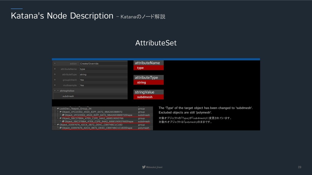
attributeType string stringValue subdmesh 対象オブジェクトの「Type」が「subdmesh」に変更されています。 対象外オブジェクトは「polymesh」のままです。 The 'Type' of the target object has been changed to 'subdmesh'. Excluded objects are still 'polymesh'.
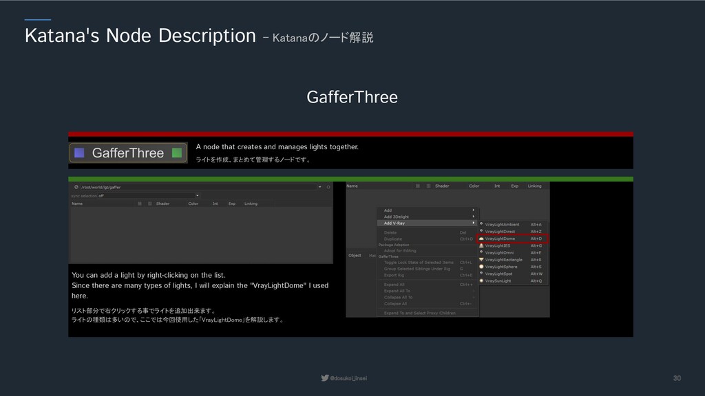
A node that creates and manages lights together. リスト部分で右クリックする事でライトを追加出来ます。 ライトの種類は多いので、ここでは今回使用した「VrayLightDome」を解説します。 You can add a light by right-clicking on the list. Since there are many types of lights, I will explain the "VrayLightDome" I used here.
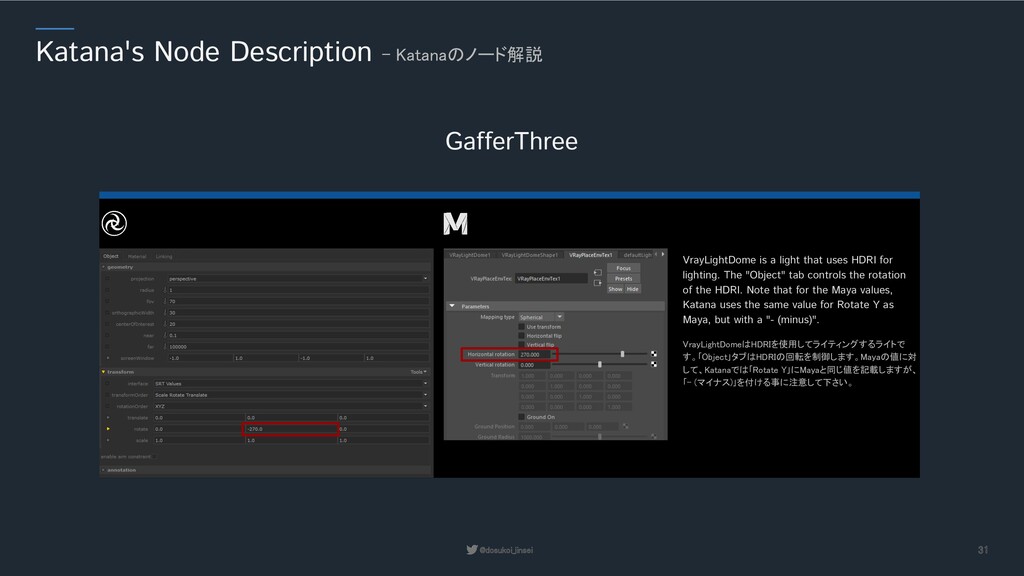
して、Katanaでは「Rotate Y」にMayaと同じ値を記載しますが、 「- (マイナス)」を付ける事に注意して下さい。 VrayLightDome is a light that uses HDRI for lighting. The "Object" tab controls the rotation of the HDRI. Note that for the Maya values, Katana uses the same value for Rotate Y as Maya, but with a "- (minus)".
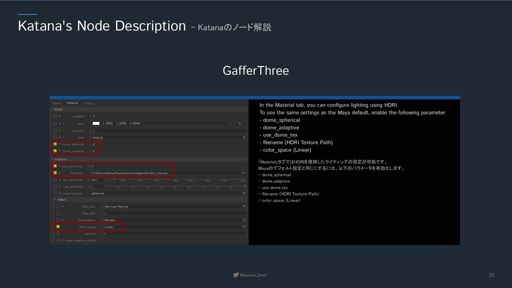
Mayaのデフォルト設定と同じにするには、以下のパラメータを有効化します。 - dome_spherical - dome_adaptive - use_dome_tex - filename (HDRI Texture Path) - color_space (Linear) In the Material tab, you can configure lighting using HDRI. To use the same settings as the Maya default, enable the following parameter - dome_spherical - dome_adaptive - use_dome_tex - filename (HDRI Texture Path) - color_space (Linear)
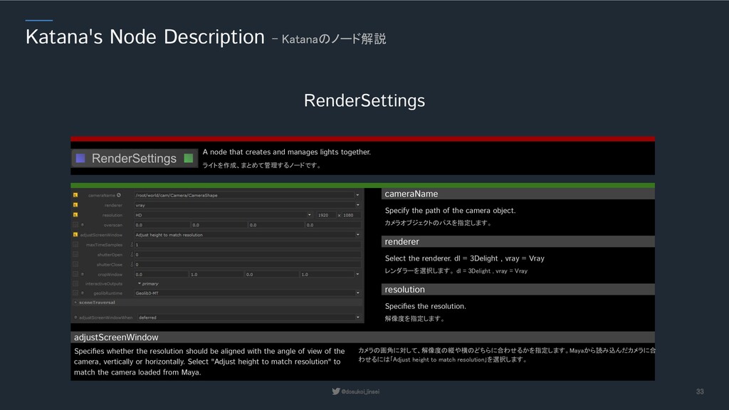
A node that creates and manages lights together. カメラオブジェクトのパスを指定します。 Specify the path of the camera object. cameraName レンダラーを選択します。 dl = 3Delight , vray = Vray Select the renderer. dl = 3Delight , vray = Vray renderer 解像度を指定します。 Specifies the resolution. resolution カメラの画角に対して、解像度の縦や横のどちらに合わせるかを指定します。Mayaから読み込んだカメラに合 わせるには「Adjust height to match resolution」を選択します。 Specifies whether the resolution should be aligned with the angle of view of the camera, vertically or horizontally. Select "Adjust height to match resolution" to match the camera loaded from Maya. adjustScreenWindow
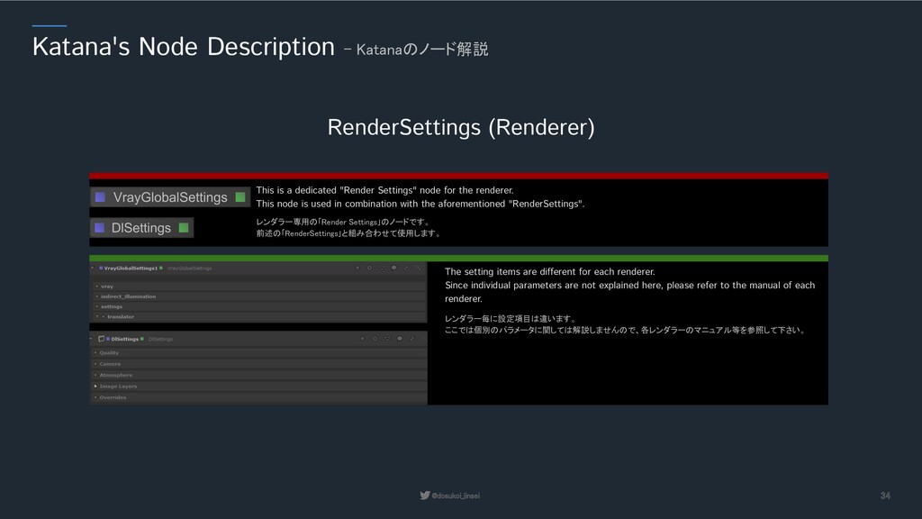
Settings」のノードです。 前述の「RenderSettings」と組み合わせて使用します。 This is a dedicated "Render Settings" node for the renderer. This node is used in combination with the aforementioned "RenderSettings". レンダラー毎に設定項目は違います。 ここでは個別のパラメータに関しては解説しませんので、各レンダラーのマニュアル等を参照して下さい。 The setting items are different for each renderer. Since individual parameters are not explained here, please refer to the manual of each renderer.
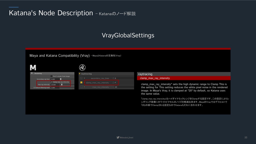
Katana Compatibility (Vray) - MayaとKatanaの互換性(Vray) raytracing clamp_max_ray_intensity clamp_max_ray_intensity" sets the high dynamic range to Clamp This is the setting for This setting reduces the white pixel noise in the rendered image. In Maya's Vray, it is clamped at "20" by default, so Katana uses the same value. 「clamp_max_ray_intensity」はハイダイナミックレンジをClampする設定です。この設定によりレ ンダリング画像にホワイトピクセルのノイズを軽減出来ます。MayaのVrayではデフォルトで 「20」の値でClampされる設定なのでKatanaもそれに合わせます。
Katana Compatibility (Vray) - MayaとKatanaの互換性(Vray) image_sampler sampler_type Vray requires the use of a "bucket" to output some of the Render Elements. We use Bucket in Maya by default, so in Katana we select Adaptive. Vrayでは一部のRender Elementsを出力するのに「Bucket」を使用する必要があります。Maya でBucketを標準使用していますので、Katanaでは「Adaptive」を選択します。
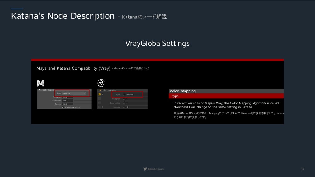
Katana Compatibility (Vray) - MayaとKatanaの互換性(Vray) color_mapping type In recent versions of Maya's Vray, the Color Mapping algorithm is called "Reinhard I will change to the same setting in Katana. 最近のMayaのVrayではColor Mappingのアルゴリズムが「Reinhard」に変更されました。Katana でも同じ設定に変更します。
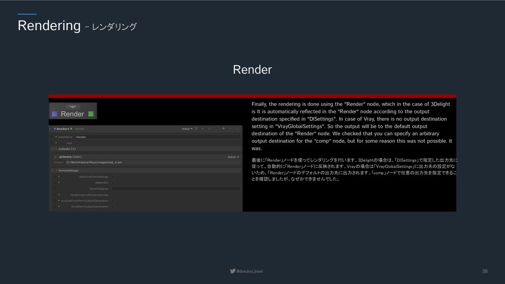
Finally, the rendering is done using the "Render" node, which in the case of 3Delight is It is automatically reflected in the "Render" node according to the output destination specified in "DlSettings". In case of Vray, there is no output destination setting in "VrayGlobalSettings". So the output will be to the default output destination of the "Render" node. We checked that you can specify an arbitrary output destination for the "comp" node, but for some reason this was not possible. It was.