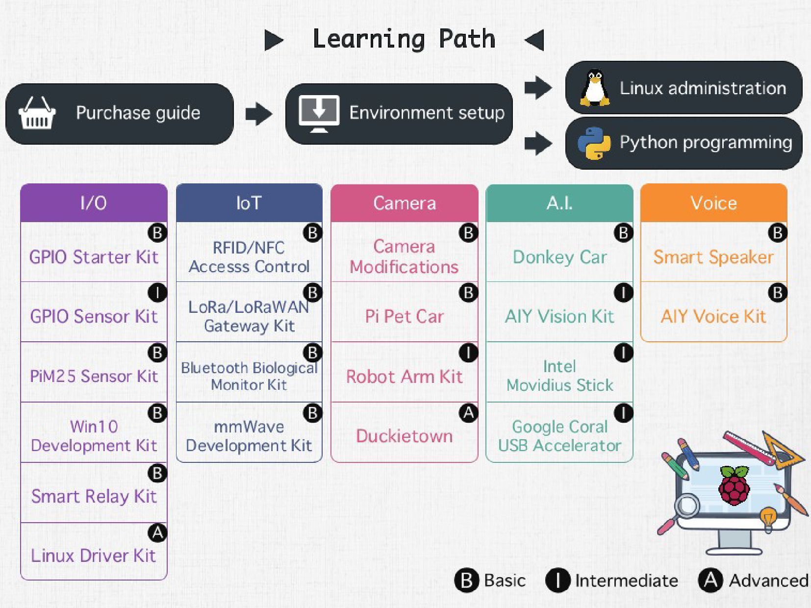
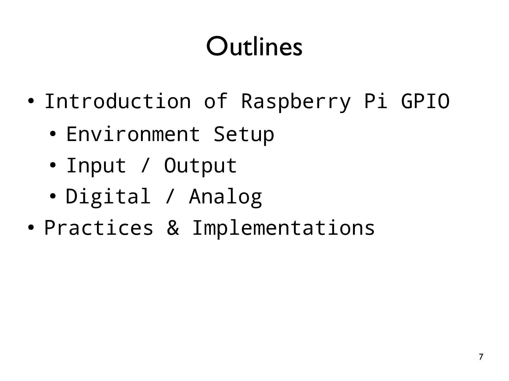
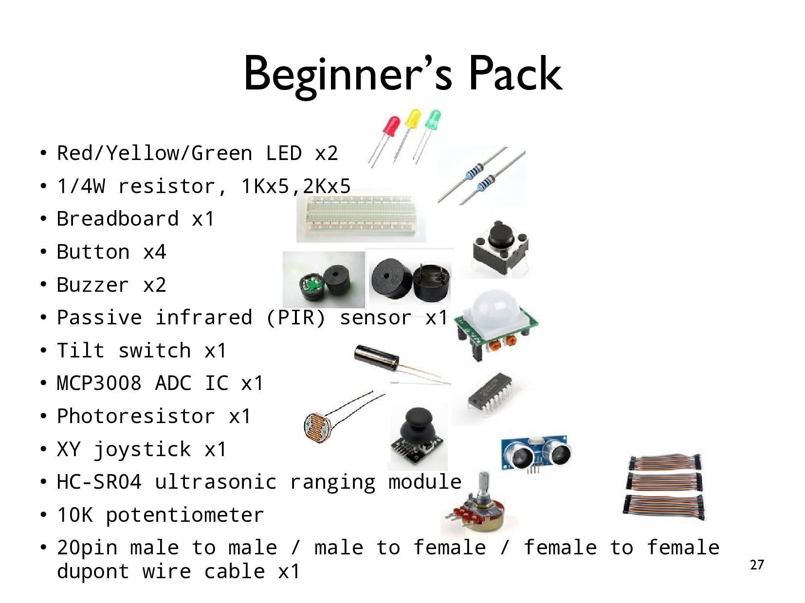
Learning from scratch, we design 20 labs to help you learn the Raspberry Pi GPIO.
What topics are included?
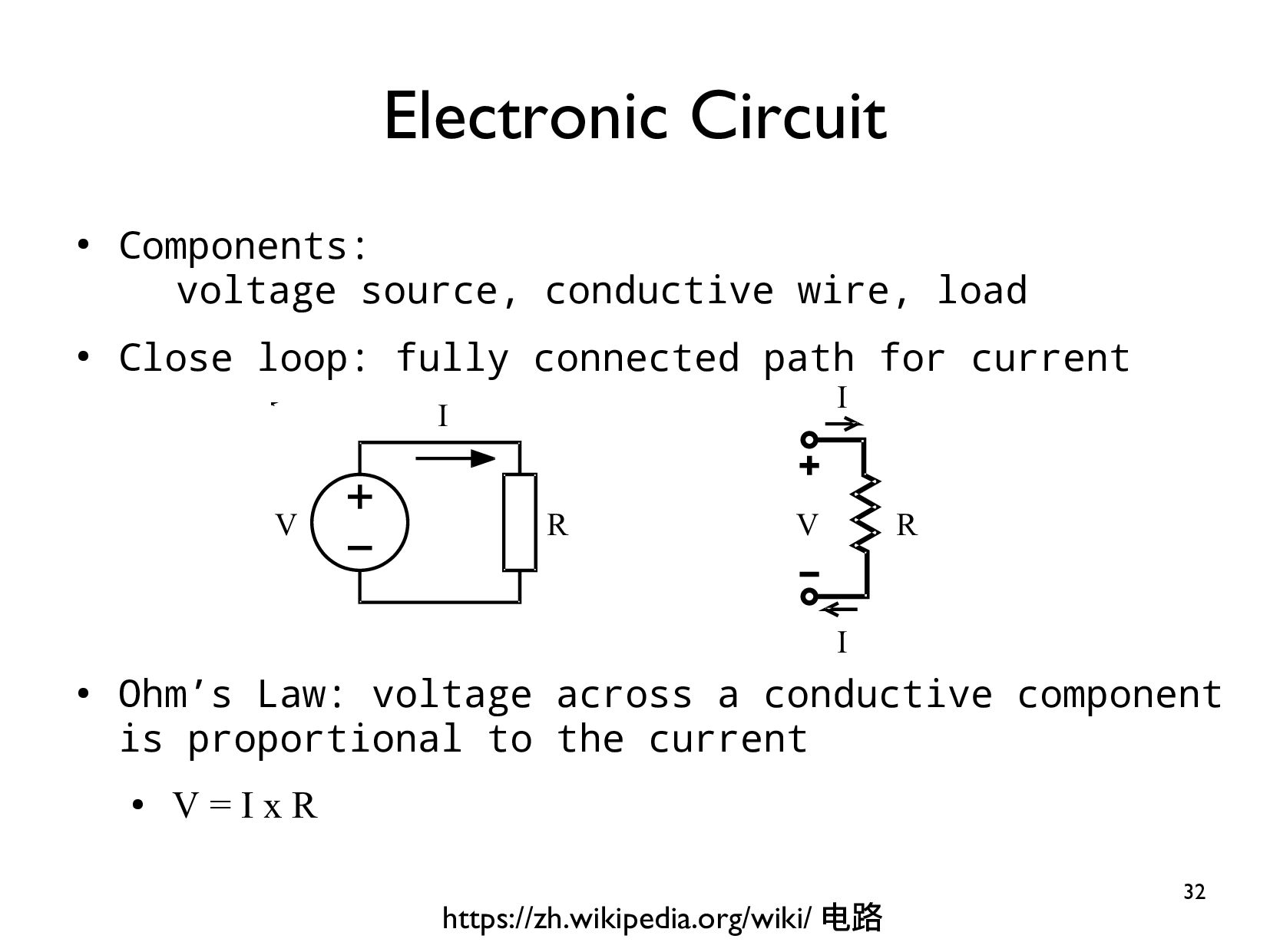
* Basic electronic theory
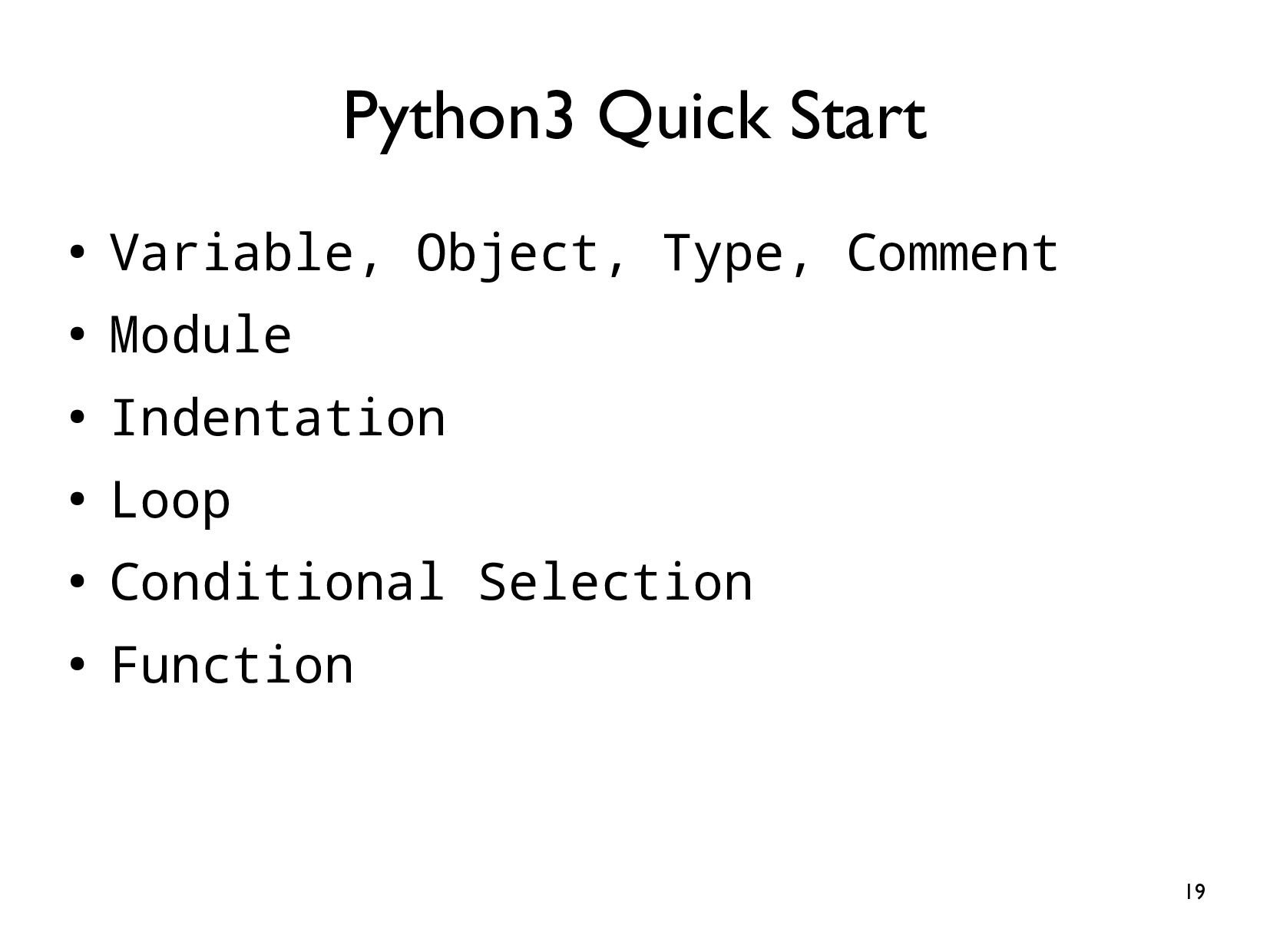
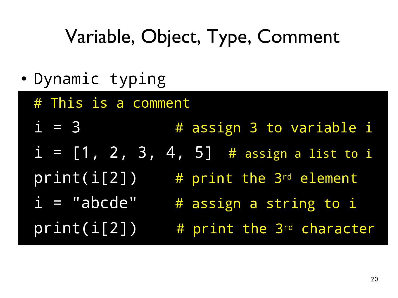
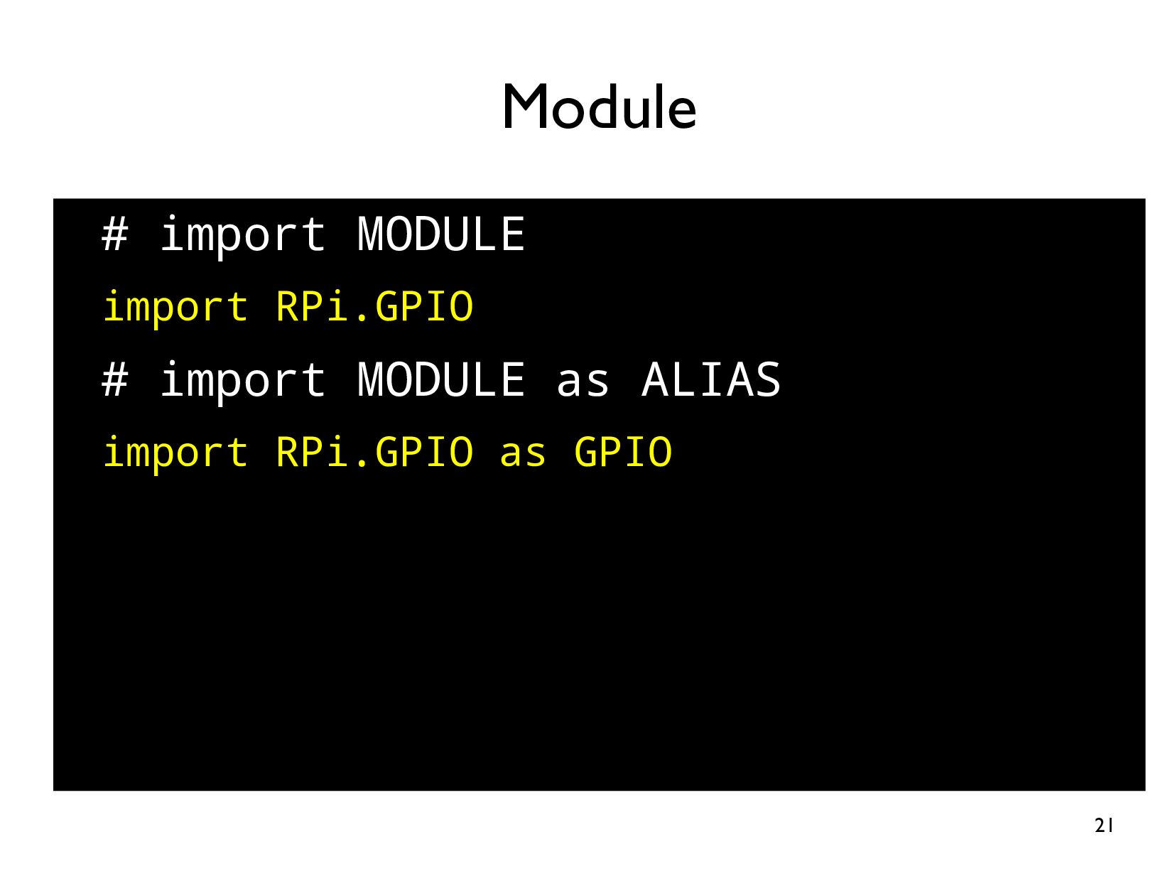
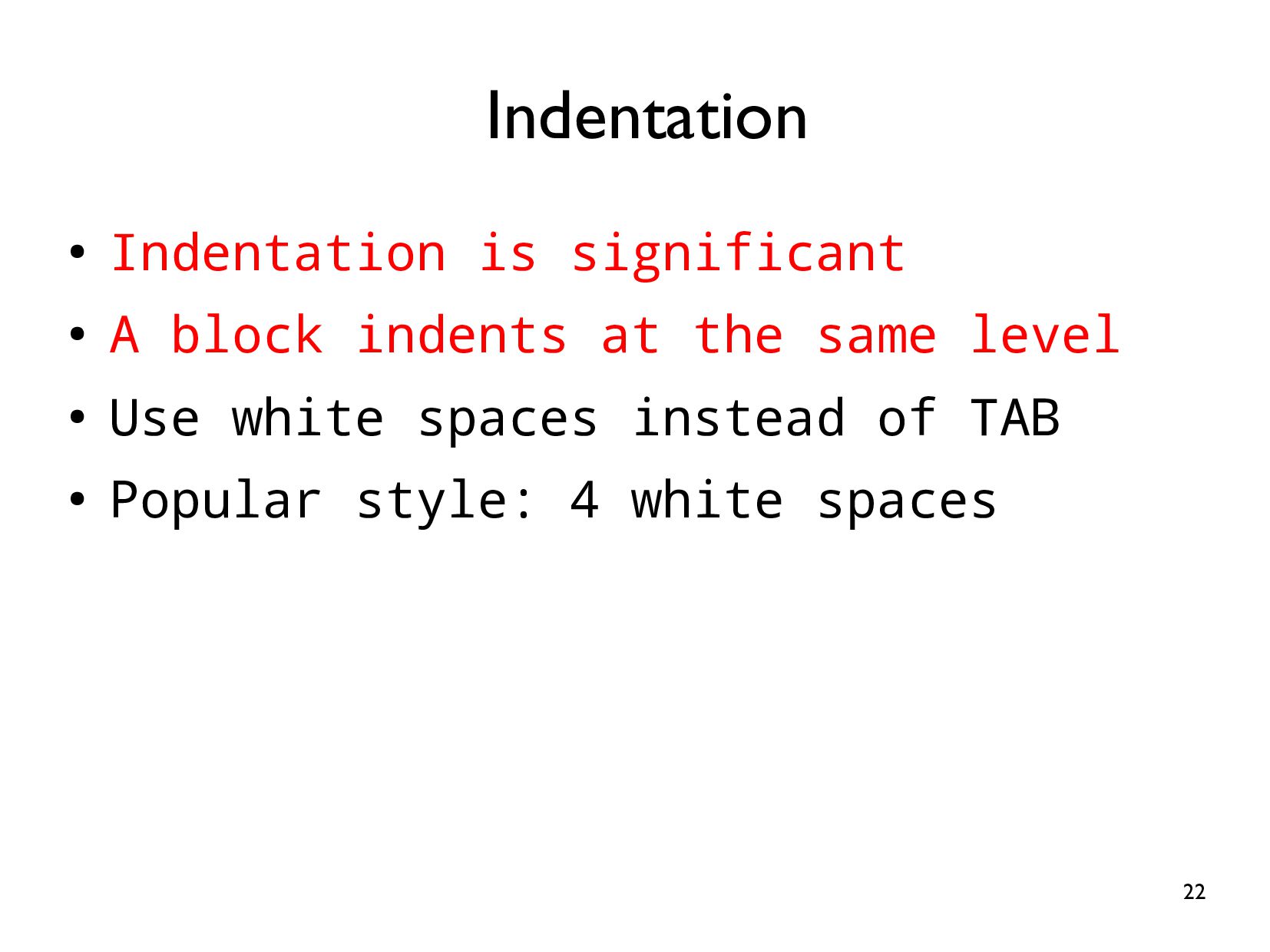
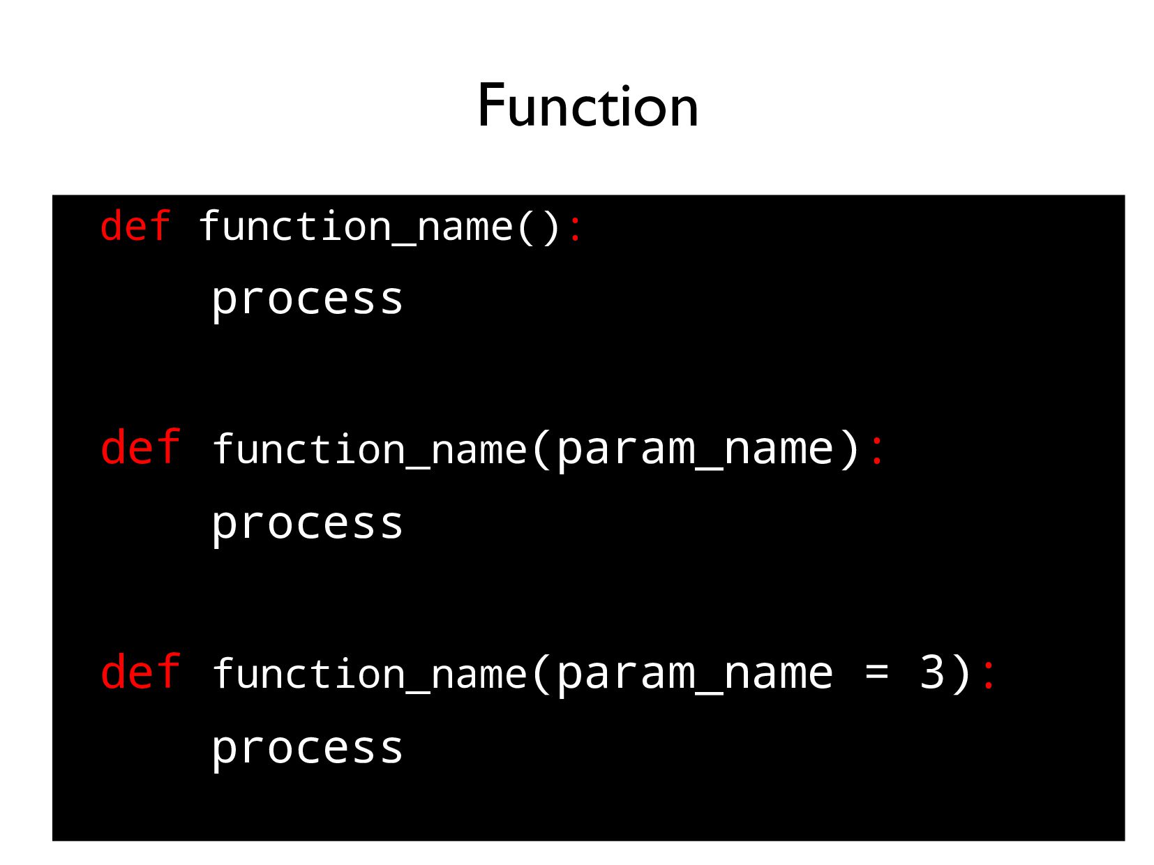
* Basic Python syntax
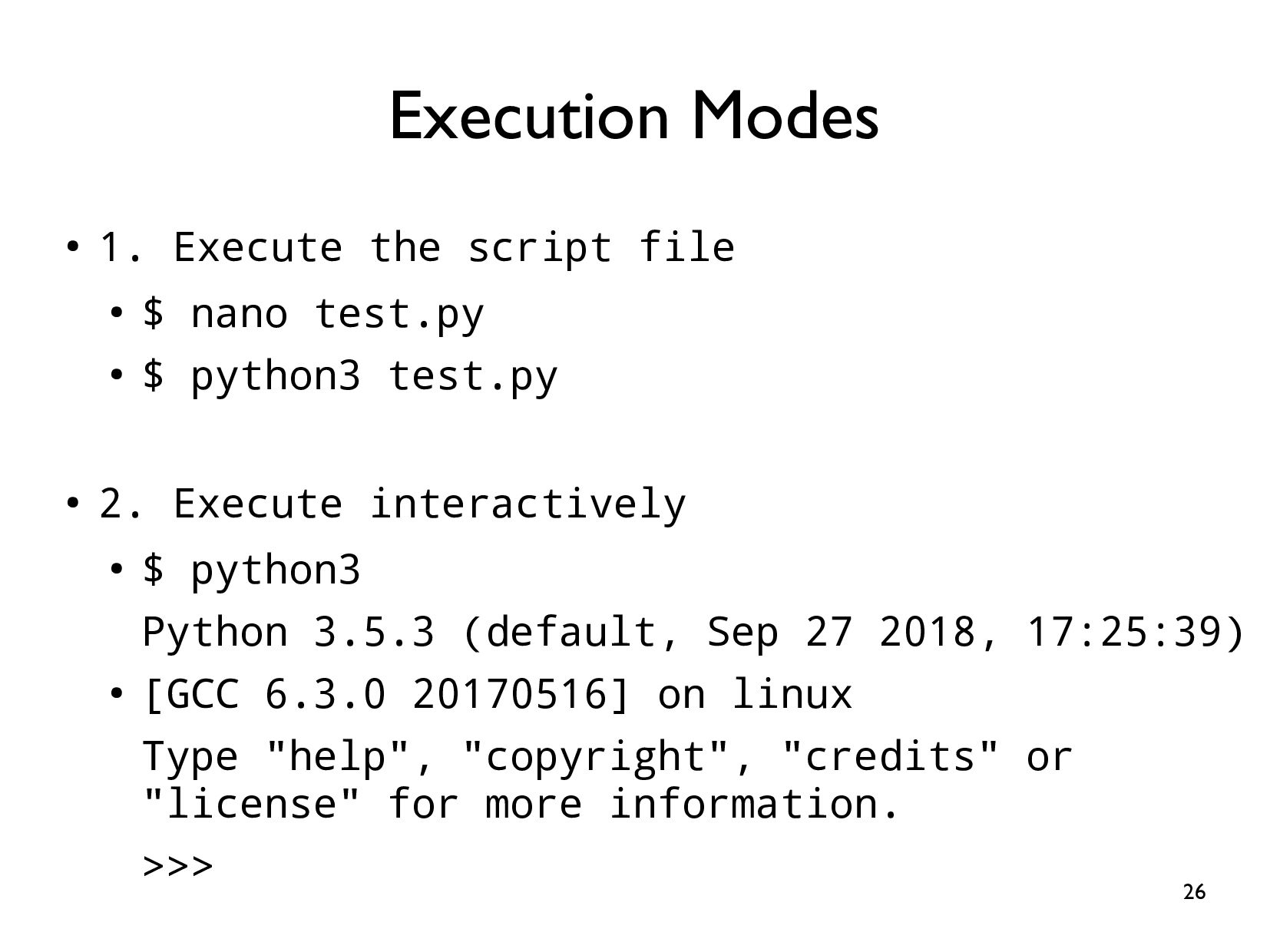
* Basic Linux command
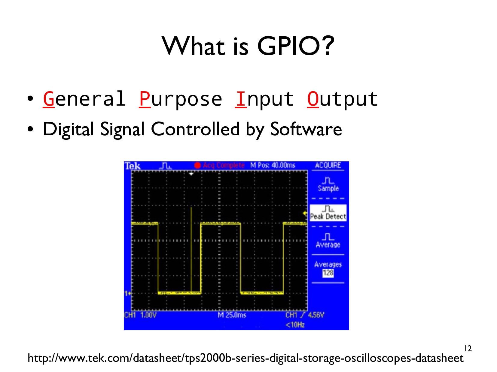
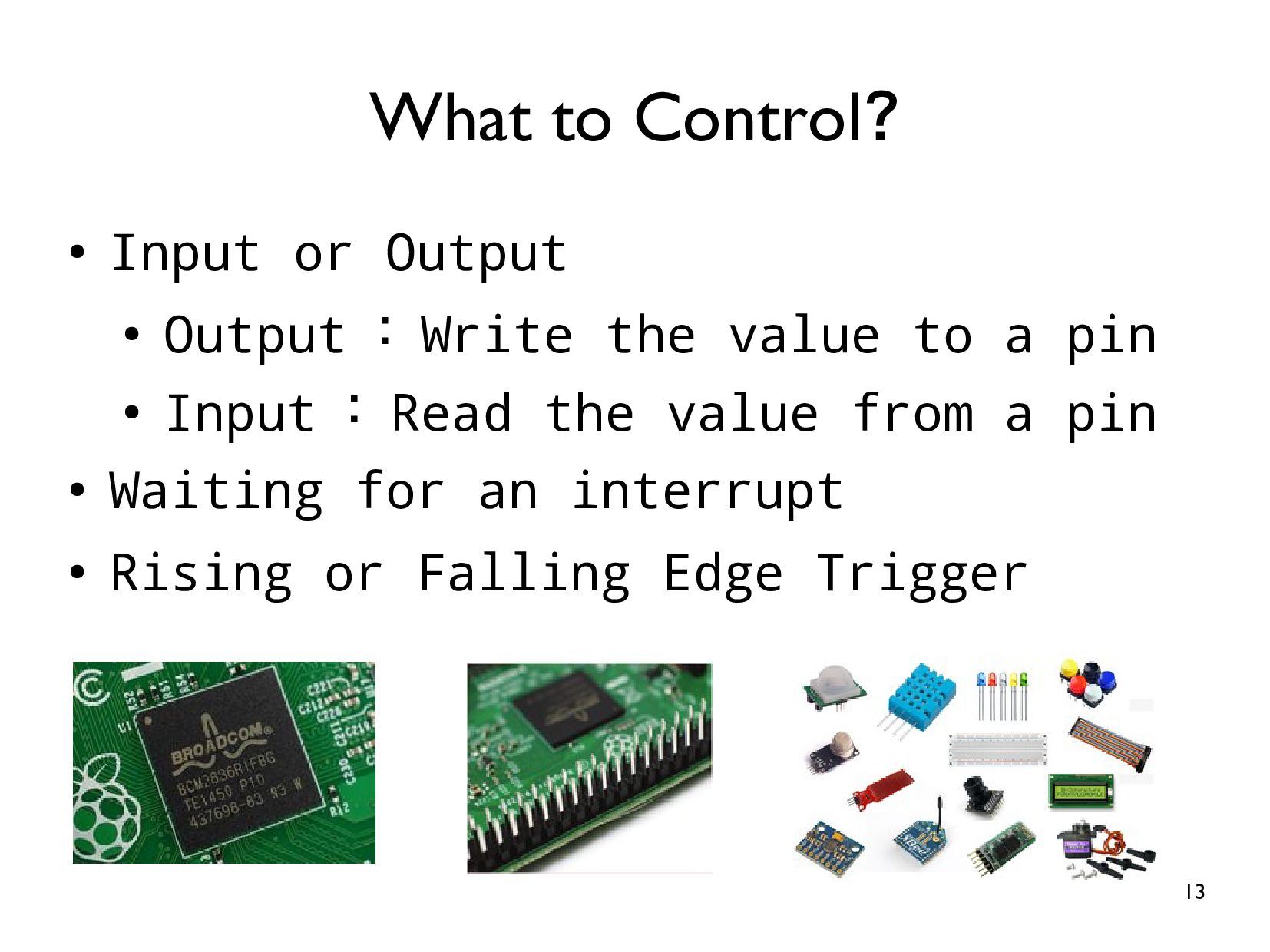
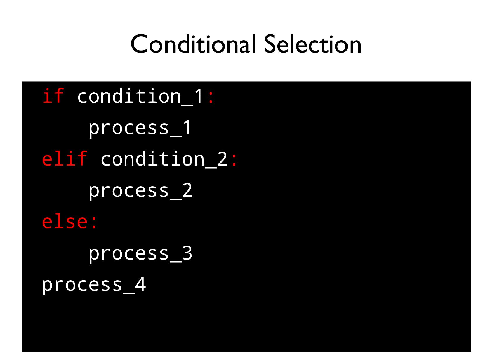
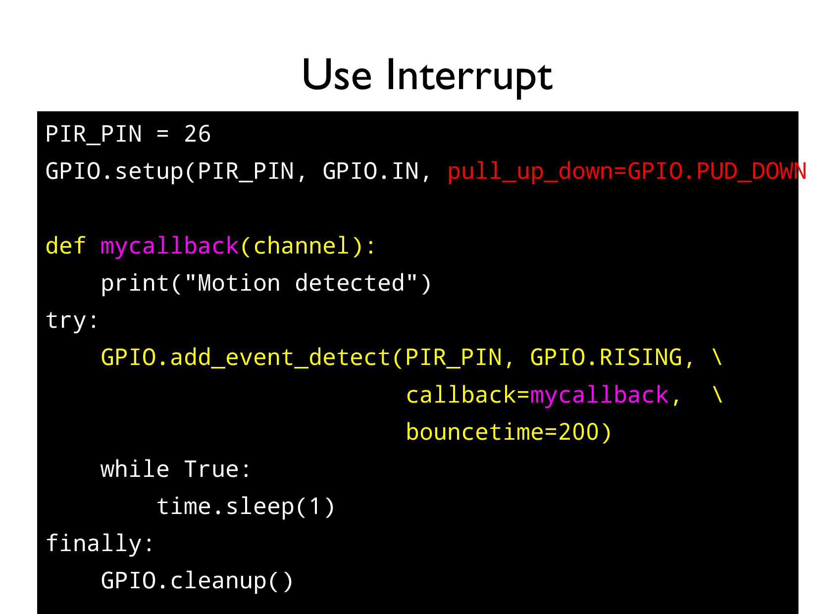
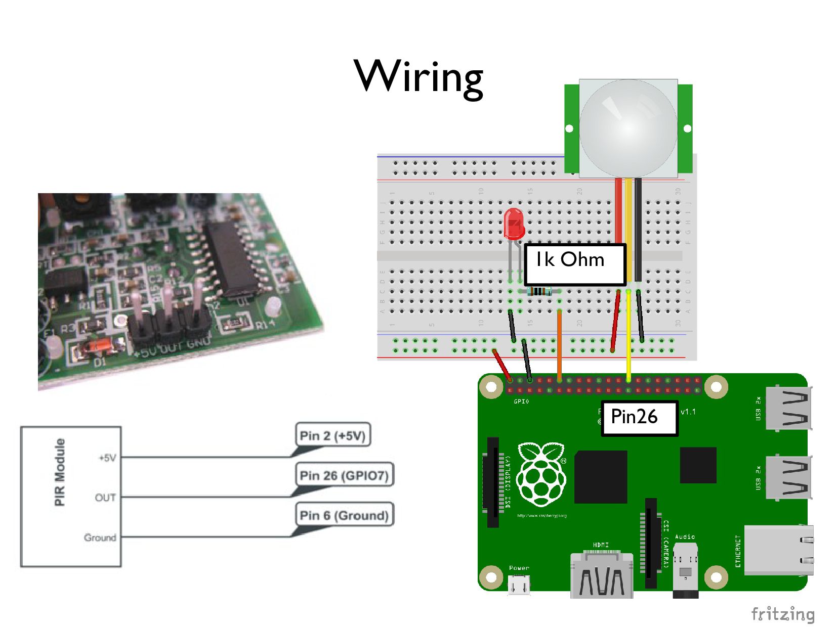
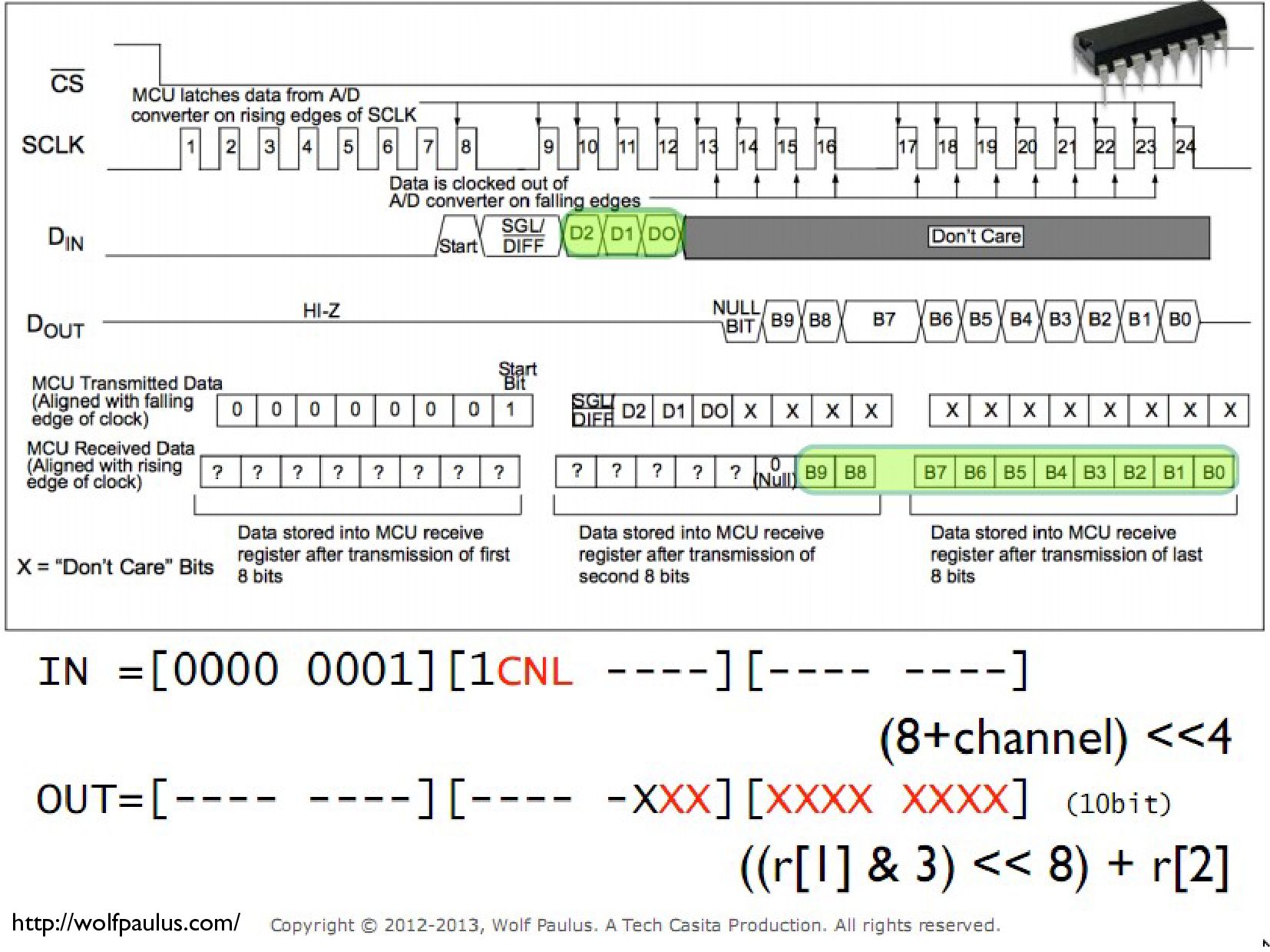
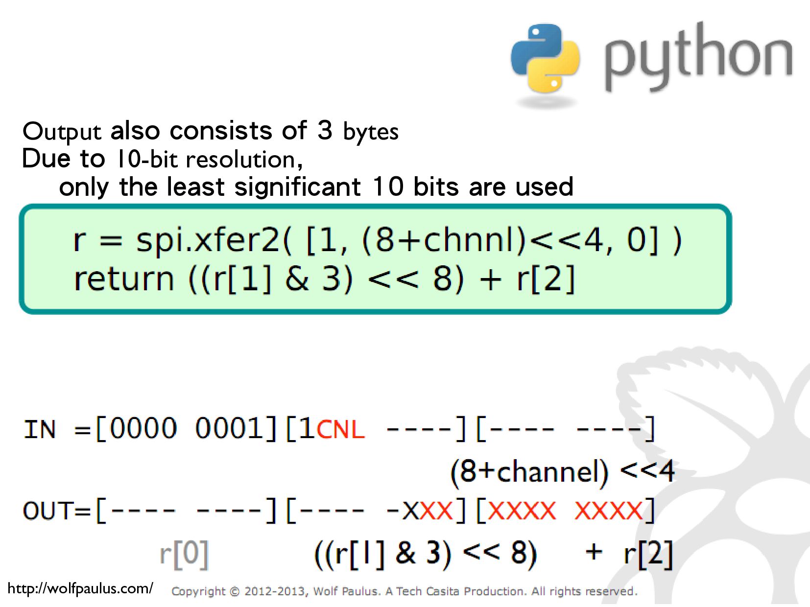
* Basic digital input/digital output/analog input/analog output
* System integration
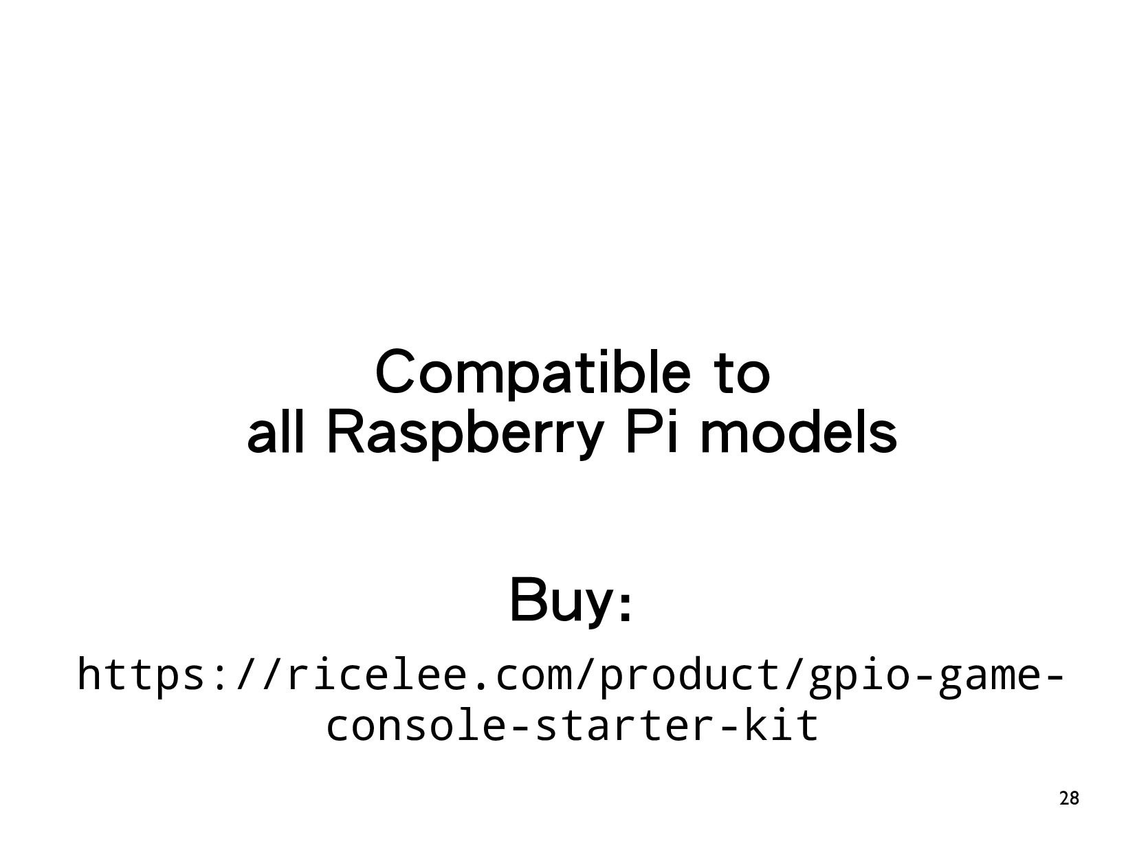
Buy:
https://ricelee.com/product/gpio-game-console-starter-kit
Source:
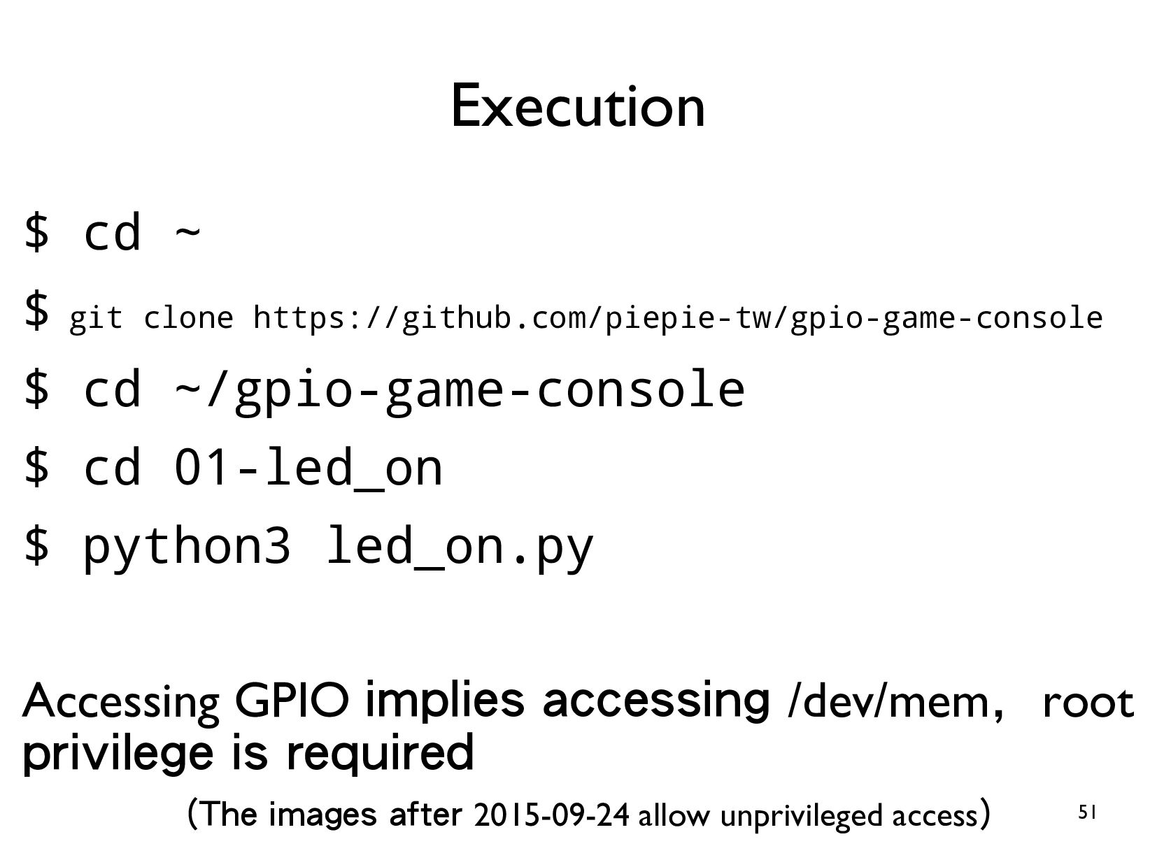
https://github.com/piepie-tw/gpio-game-console
![23 • Iterator for i in range(start, stop[, step]): process](https://files.speakerdeck.com/presentations/6d1ce594328342ae89f82f86f3c64a68/slide_22.jpg)