Ren Goto1), Taiki Yoshikawa2), Hijiri Komura2), Kazushige Matama1), Chihiro Nishiwaki2), Katsuhiro Naito1) 1) Faculty of Information Science, Aichi Institute of Technology 2) Graduate School of Business Administration and Computer Science, Aichi Institute of Technology 2022, March, 8 The 13th International Multi-Conference on Complexity, Informatics and Cybernetics: IMCIC 2022 1
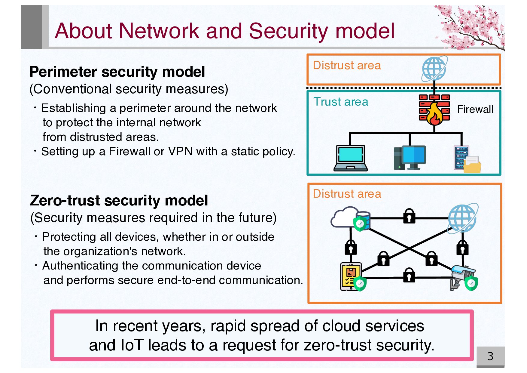
spread of cloud services and IoT leads to a request for zero-trust security. Perimeter security model (Conventional security measures) ・Establishing a perimeter around the network to protect the internal network from distrusted areas. ・Setting up a Firewall or VPN with a static policy. Zero-trust security model (Security measures required in the future) ・Protecting all devices, whether in or outside the organization's network. ・Authenticating the communication device and performs secure end-to-end communication. Firewall Distrust area Trust area Distrust area
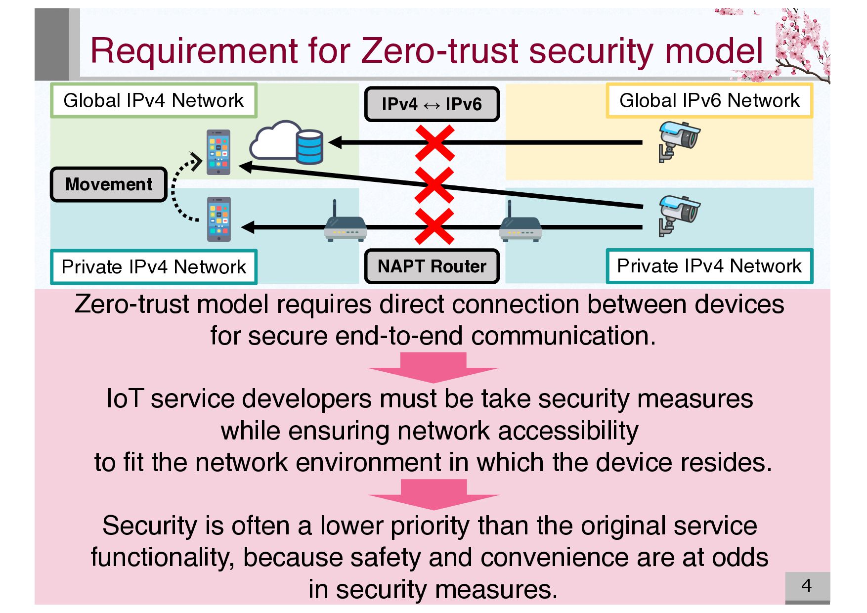
IPv4 Network Movement Private IPv4 Network Global IPv6 Network NAPT Router IPv4 ↔ IPv6 Zero-trust model requires direct connection between devices for secure end-to-end communication. IoT service developers must be take security measures while ensuring network accessibility to fit the network environment in which the device resides. Security is often a lower priority than the original service functionality, because safety and convenience are at odds in security measures.
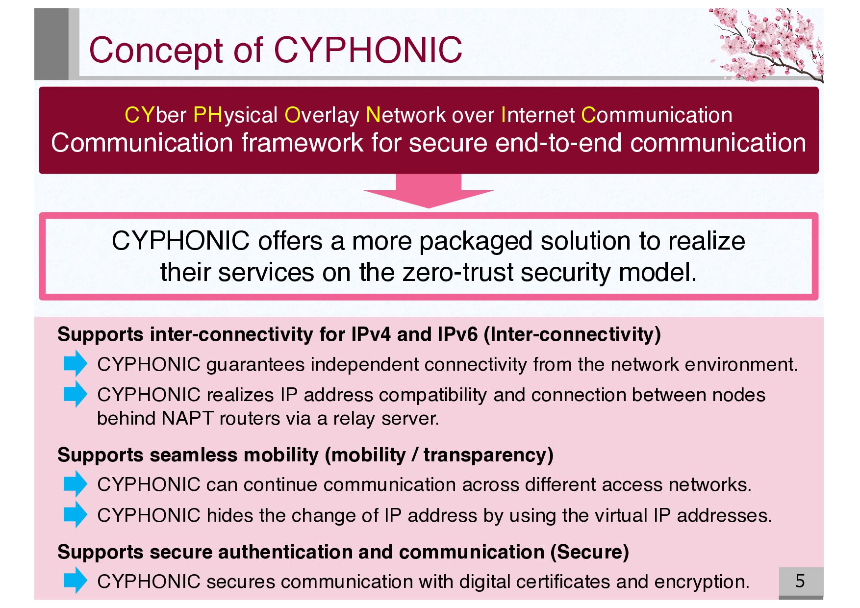
to realize their services on the zero-trust security model. CYber PHysical Overlay Network over Internet Communication Communication framework for secure end-to-end communication Supports inter-connectivity for IPv4 and IPv6 (Inter-connectivity) CYPHONIC guarantees independent connectivity from the network environment. CYPHONIC realizes IP address compatibility and connection between nodes behind NAPT routers via a relay server. Supports seamless mobility (mobility / transparency) CYPHONIC can continue communication across different access networks. CYPHONIC hides the change of IP address by using the virtual IP addresses. Supports secure authentication and communication (Secure) CYPHONIC secures communication with digital certificates and encryption.
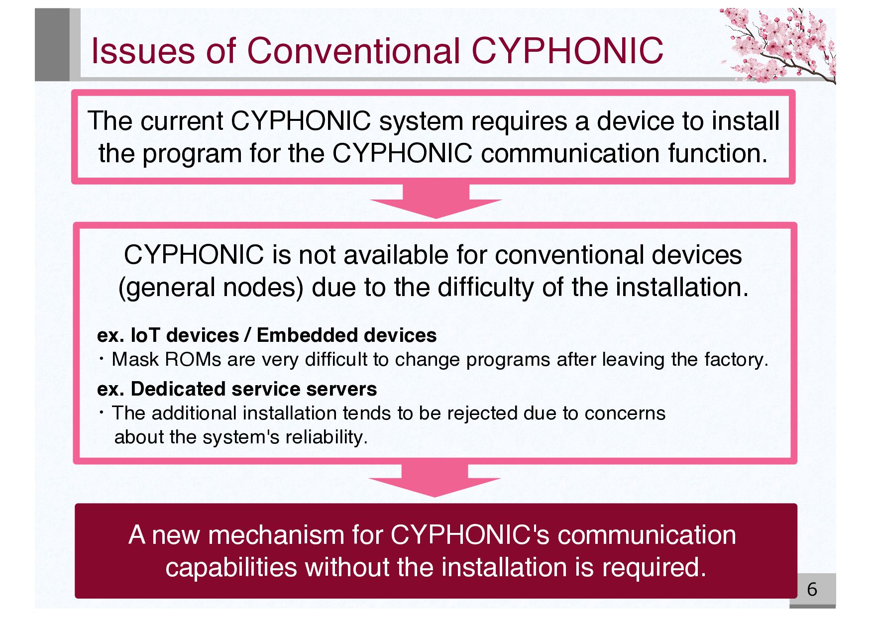
a device to install the program for the CYPHONIC communication function. CYPHONIC is not available for conventional devices (general nodes) due to the difficulty of the installation. ex. IoT devices / Embedded devices ・Mask ROMs are very difficult to change programs after leaving the factory. ex. Dedicated service servers ・The additional installation tends to be rejected due to concerns about the system's reliability. A new mechanism for CYPHONIC's communication capabilities without the installation is required.
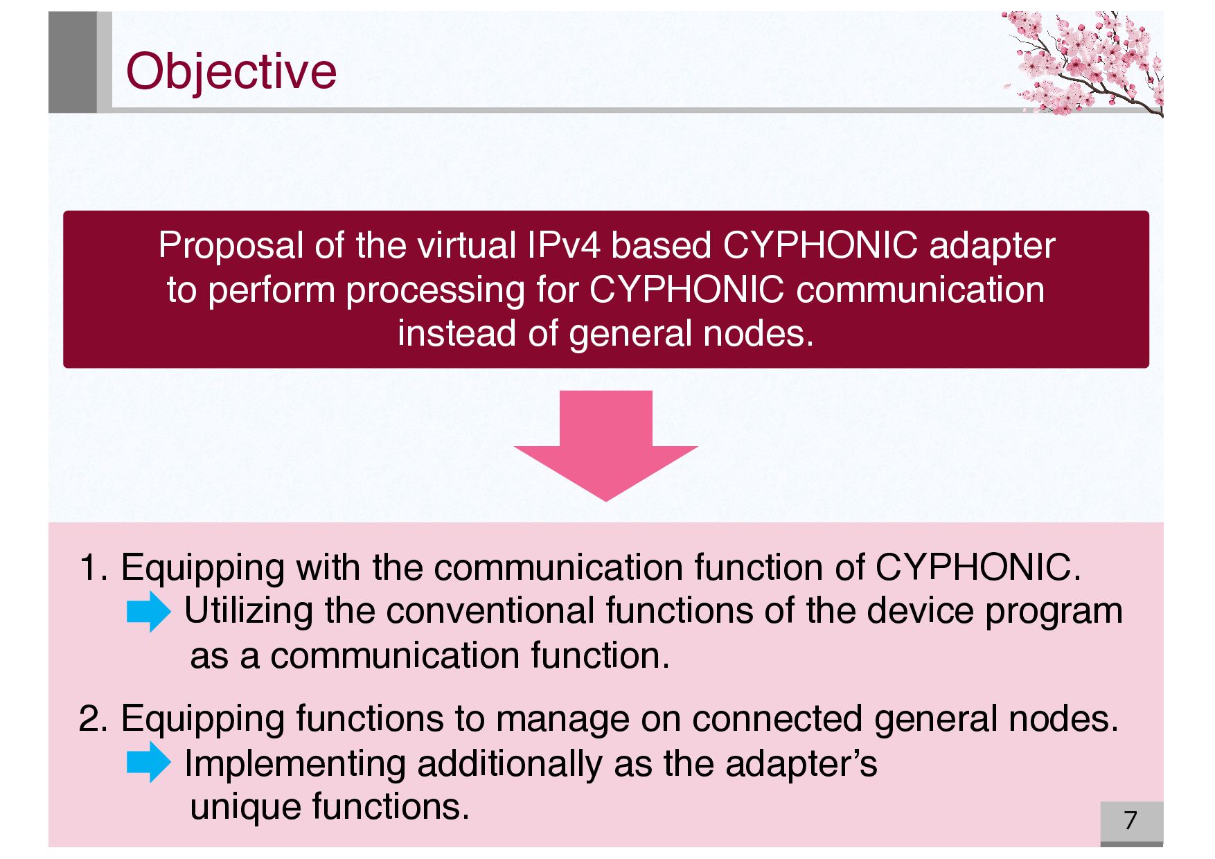
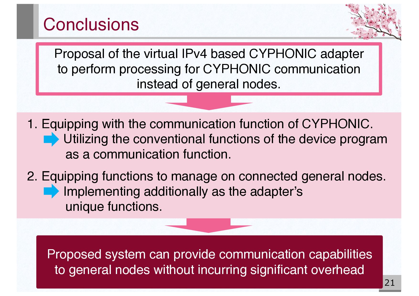
to perform processing for CYPHONIC communication instead of general nodes. 1. Equipping with the communication function of CYPHONIC. Utilizing the conventional functions of the device program as a communication function. 2. Equipping functions to manage on connected general nodes. Implementing additionally as the adapter’s unique functions.
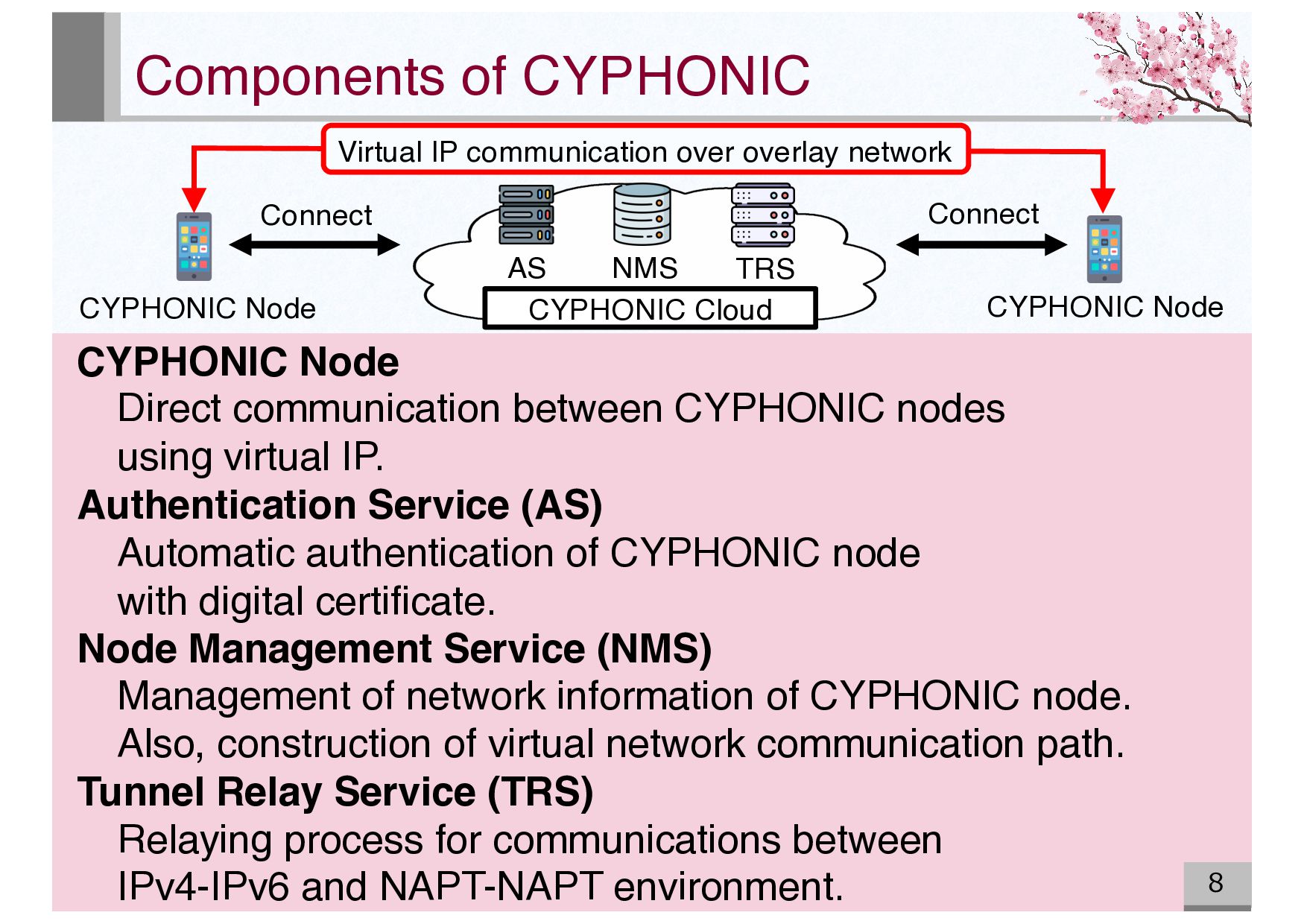
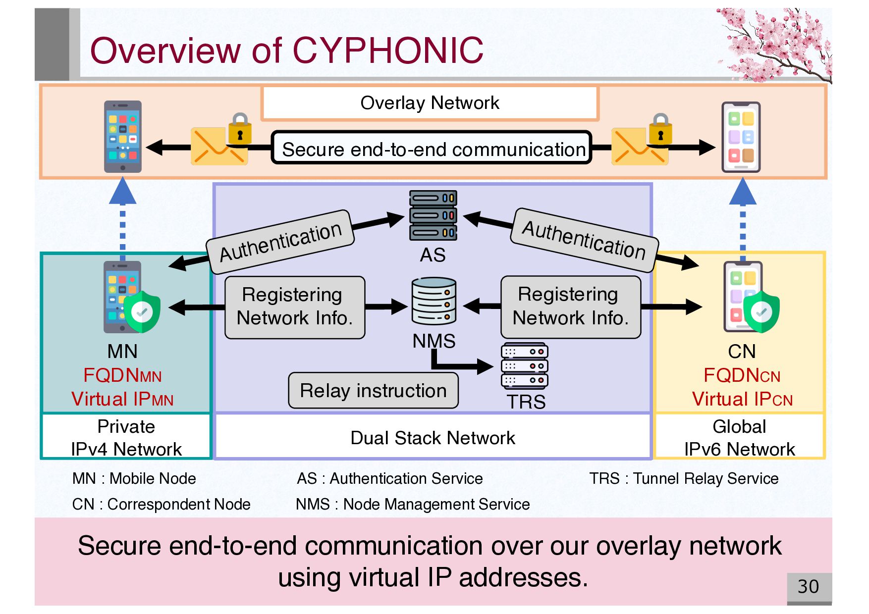
AS Connect Connect CYPHONIC Node Virtual IP communication over overlay network CYPHONIC Node Direct communication between CYPHONIC nodes using virtual IP. Authentication Service (AS) Automatic authentication of CYPHONIC node with digital certificate. Node Management Service (NMS) Management of network information of CYPHONIC node. Also, construction of virtual network communication path. Tunnel Relay Service (TRS) Relaying process for communications between IPv4-IPv6 and NAPT-NAPT environment.
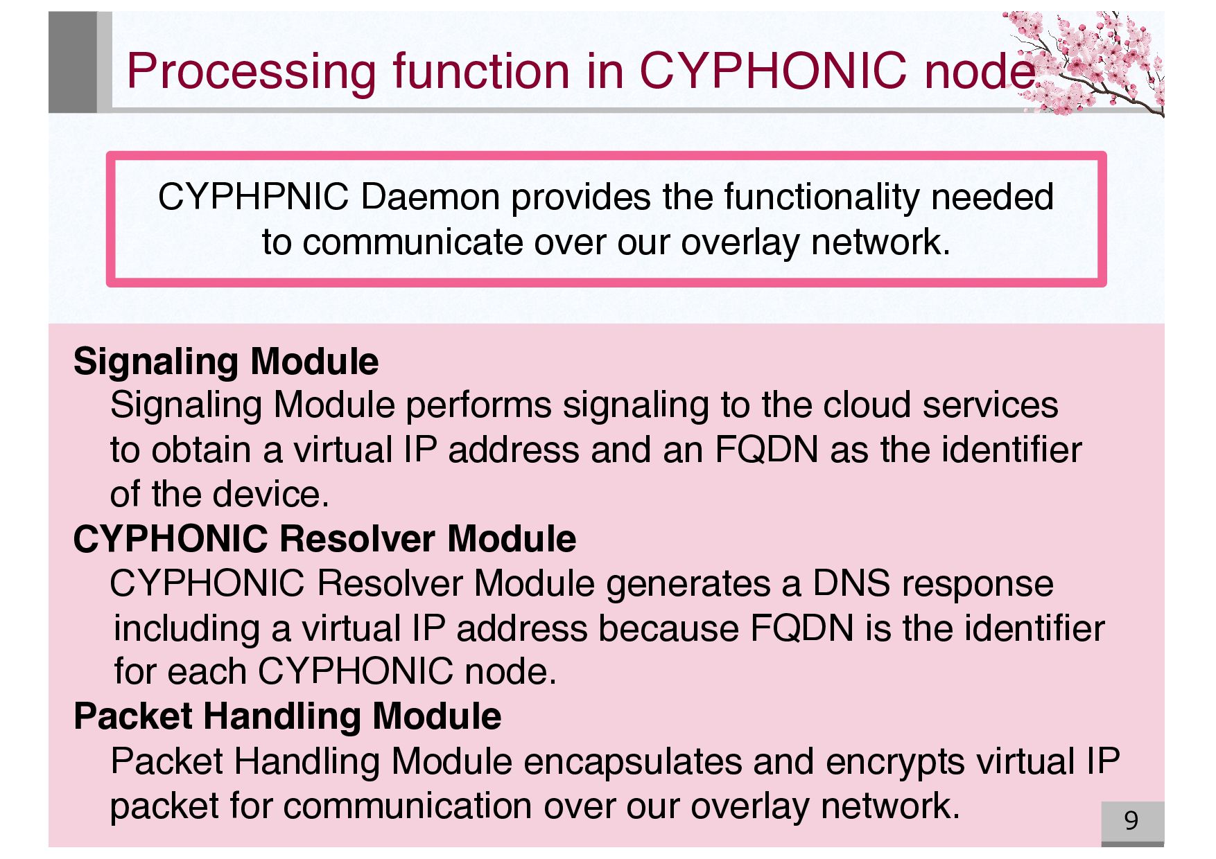
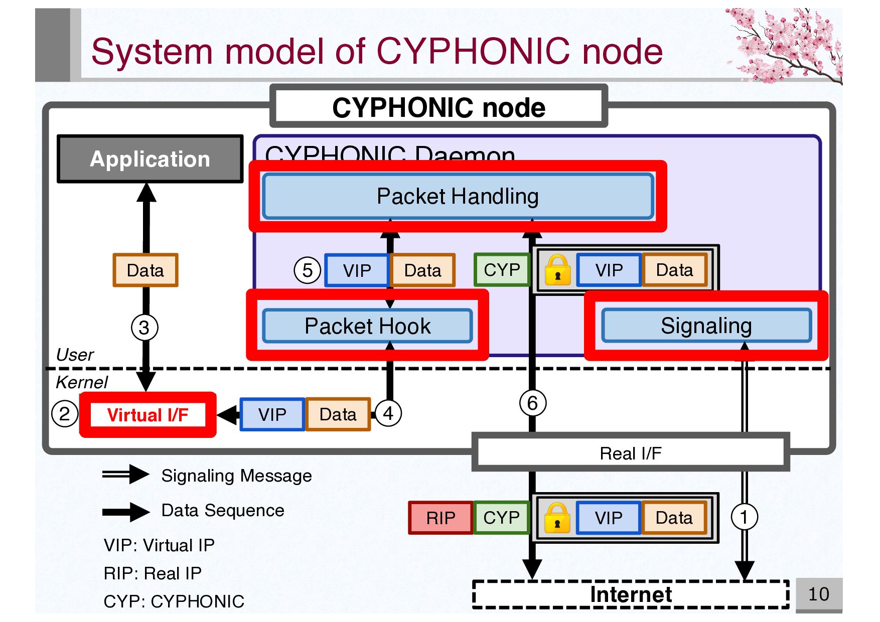
functionality needed to communicate over our overlay network. Signaling Module Signaling Module performs signaling to the cloud services to obtain a virtual IP address and an FQDN as the identifier of the device. CYPHONIC Resolver Module CYPHONIC Resolver Module generates a DNS response including a virtual IP address because FQDN is the identifier for each CYPHONIC node. Packet Handling Module Packet Handling Module encapsulates and encrypts virtual IP packet for communication over our overlay network.
Real IP CYP: CYPHONIC Signaling Message Data Sequence CYPHONIC node Virtual I/F Internet CYPHONIC Daemon Application Packet Handling CYP VIP Data RIP CYP VIP Data Packet Hook VIP Data Kernel User Data VIP Data 6 2 3 4 5 Signaling 1 Real I/F
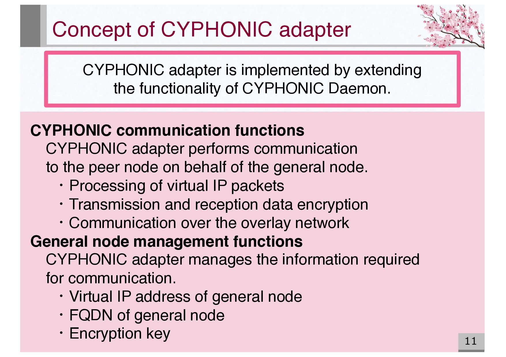
extending the functionality of CYPHONIC Daemon. CYPHONIC communication functions CYPHONIC adapter performs communication to the peer node on behalf of the general node. ・Processing of virtual IP packets ・Transmission and reception data encryption ・Communication over the overlay network General node management functions CYPHONIC adapter manages the information required for communication. ・Virtual IP address of general node ・FQDN of general node ・Encryption key
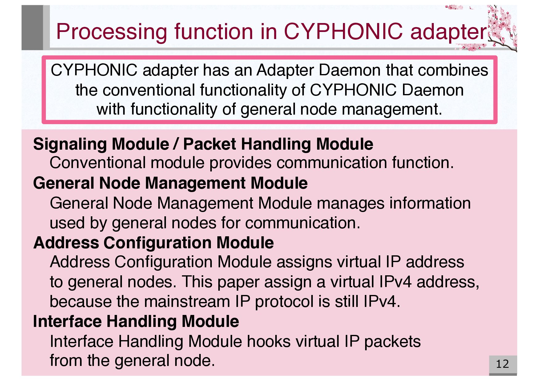
Adapter Daemon that combines the conventional functionality of CYPHONIC Daemon with functionality of general node management. Signaling Module / Packet Handling Module Conventional module provides communication function. General Node Management Module General Node Management Module manages information used by general nodes for communication. Address Configuration Module Address Configuration Module assigns virtual IP address to general nodes. This paper assign a virtual IPv4 address, because the mainstream IP protocol is still IPv4. Interface Handling Module Interface Handling Module hooks virtual IP packets from the general node.
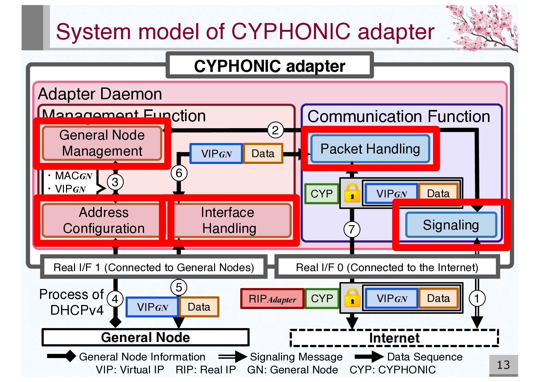
CYPHONIC adapter Adapter Daemon Management Function General Node Management Interface Handling Address Configuration Communication Function Packet Handling Signaling General Node VIP: Virtual IP RIP: Real IP GN: General Node CYP: CYPHONIC VIPGN Data Real I/F 1 (Connected to General Nodes) Real I/F 0 (Connected to the Internet) ・MACGN ・VIPGN General Node Information Signaling Message Data Sequence VIPGN Data CYP VIPGN Data CYP VIPGN Data RIPAdapter 1 2 3 4 5 6 7
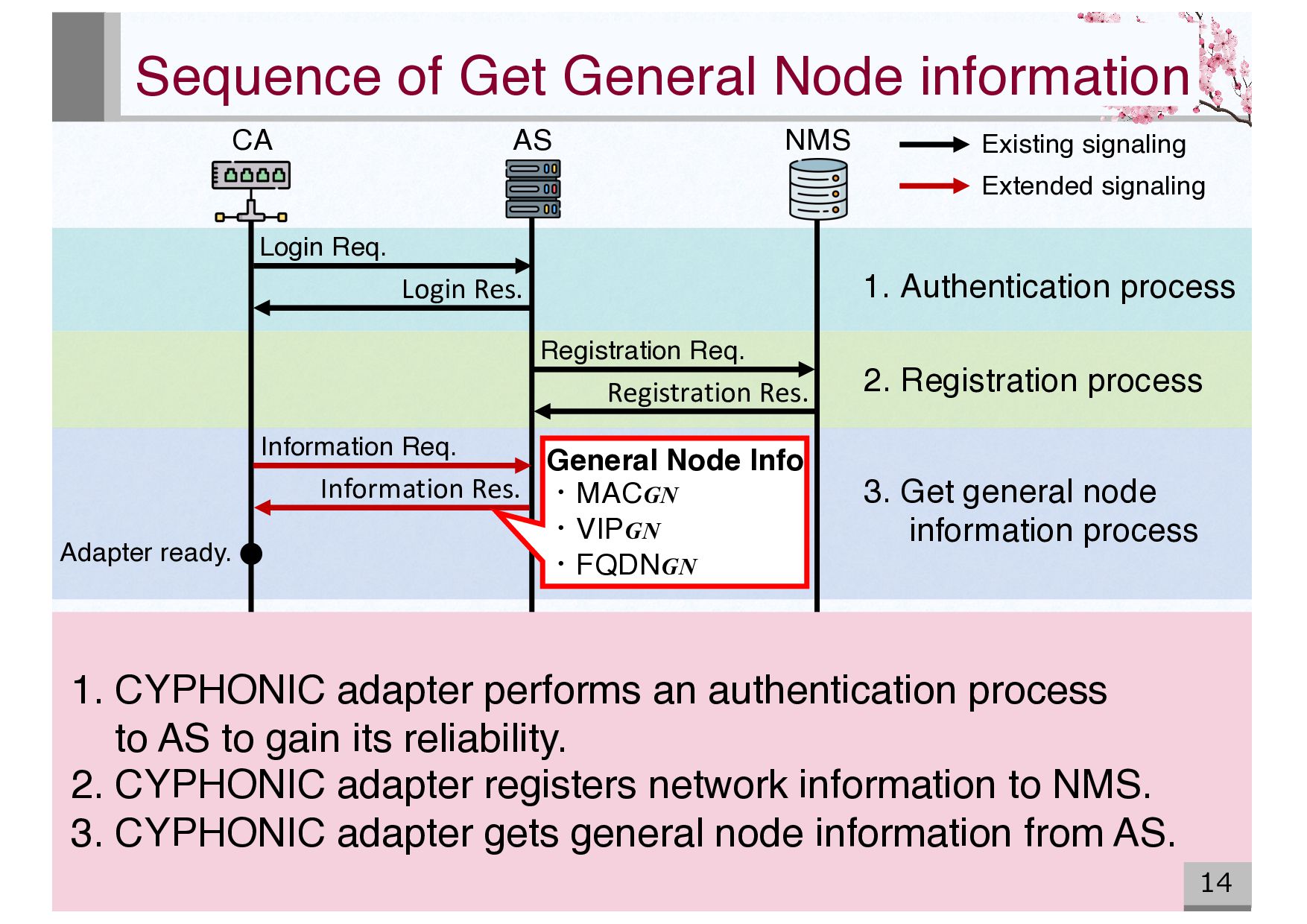
14 NMS AS CA Login Res. Registration Res. Information Req. Information Res. Adapter ready. General Node Info ・MACGN ・VIPGN ・FQDNGN 1. CYPHONIC adapter performs an authentication process to AS to gain its reliability. 2. CYPHONIC adapter registers network information to NMS. 3. CYPHONIC adapter gets general node information from AS. 1. Authentication process 2. Registration process 3. Get general node information process Existing signaling Extended signaling
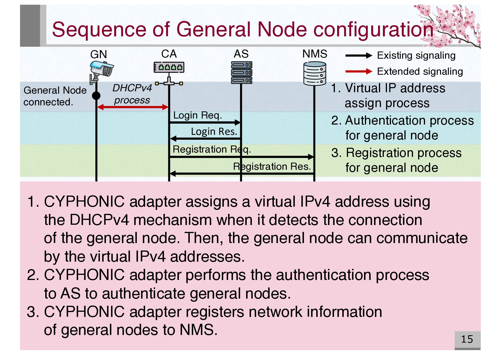
1. CYPHONIC adapter assigns a virtual IPv4 address using the DHCPv4 mechanism when it detects the connection of the general node. Then, the general node can communicate by the virtual IPv4 addresses. 2. CYPHONIC adapter performs the authentication process to AS to authenticate general nodes. 3. CYPHONIC adapter registers network information of general nodes to NMS. General Node connected. DHCPv4 process Login Req. Login Res. Registration Req. Registration Res. 2. Authentication process for general node 3. Registration process for general node 1. Virtual IP address assign process Existing signaling Extended signaling
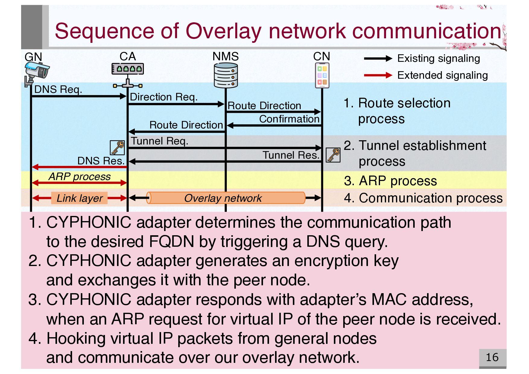
communication 16 1. CYPHONIC adapter determines the communication path to the desired FQDN by triggering a DNS query. 2. CYPHONIC adapter generates an encryption key and exchanges it with the peer node. 3. CYPHONIC adapter responds with adapter’s MAC address, when an ARP request for virtual IP of the peer node is received. 4. Hooking virtual IP packets from general nodes and communicate over our overlay network. NMS CA GN CN DNS Req. Direction Req. Confirmation Tunnel Req. Tunnel Res. DNS Res. Link layer Overlay network 1. Route selection process 2. Tunnel establishment process 3. ARP process 4. Communication process Existing signaling Extended signaling
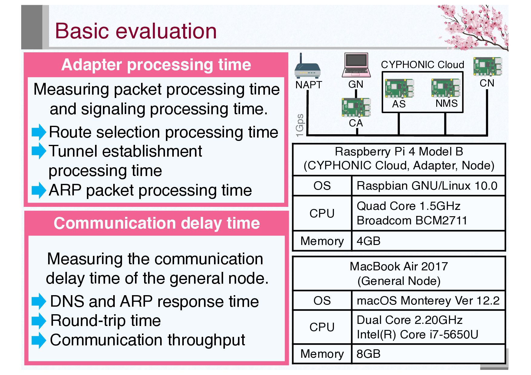
B (CYPHONIC Cloud, Adapter, Node) OS Raspbian GNU/Linux 10.0 CPU Quad Core 1.5GHz Broadcom BCM2711 Memory 4GB MacBook Air 2017 (General Node) OS macOS Monterey Ver 12.2 CPU Dual Core 2.20GHz Intel(R) Core i7-5650U Memory 8GB CA GN AS NMS CN CYPHONIC Cloud 1Gps NAPT Communication delay time Measuring the communication delay time of the general node. DNS and ARP response time Round-trip time Communication throughput Measuring packet processing time and signaling processing time. Route selection processing time Tunnel establishment processing time ARP packet processing time
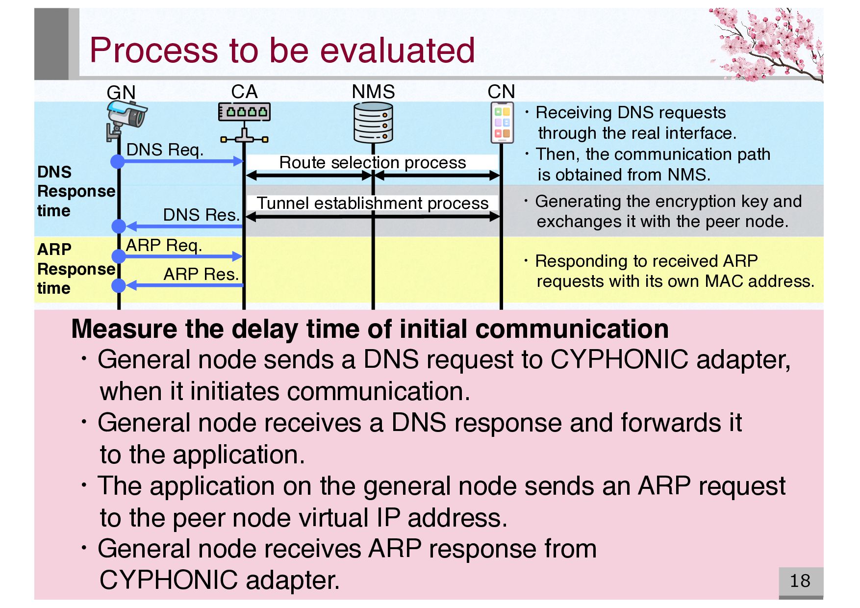
node. Process to be evaluated 18 Measure the delay time of initial communication ・General node sends a DNS request to CYPHONIC adapter, when it initiates communication. ・General node receives a DNS response and forwards it to the application. ・The application on the general node sends an ARP request to the peer node virtual IP address. ・General node receives ARP response from CYPHONIC adapter. ・Receiving DNS requests through the real interface. ・Then, the communication path is obtained from NMS. ・Responding to received ARP requests with its own MAC address. NMS CA GN CN DNS Response time ARP Response time Route selection process Tunnel establishment process ARP Req. ARP Res. DNS Res. DNS Req.
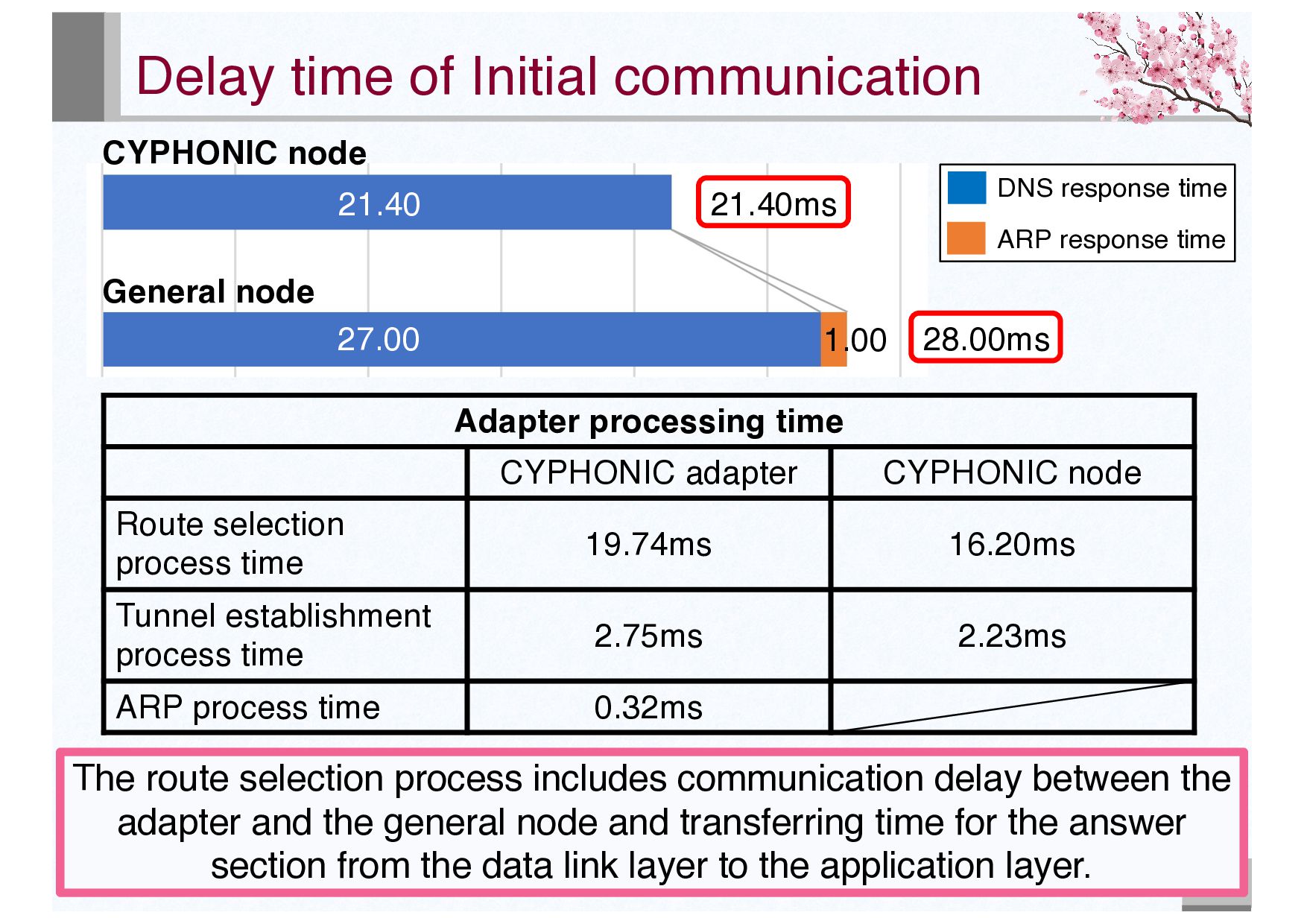
time 19.74ms 16.20ms Tunnel establishment process time 2.75ms 2.23ms ARP process time 0.32ms 19 The route selection process includes communication delay between the adapter and the general node and transferring time for the answer section from the data link layer to the application layer. Delay time of Initial communication CYPHONIC node General node 28.00ms 21.40ms 1.00 21.40 27.00 DNS response time ARP response time
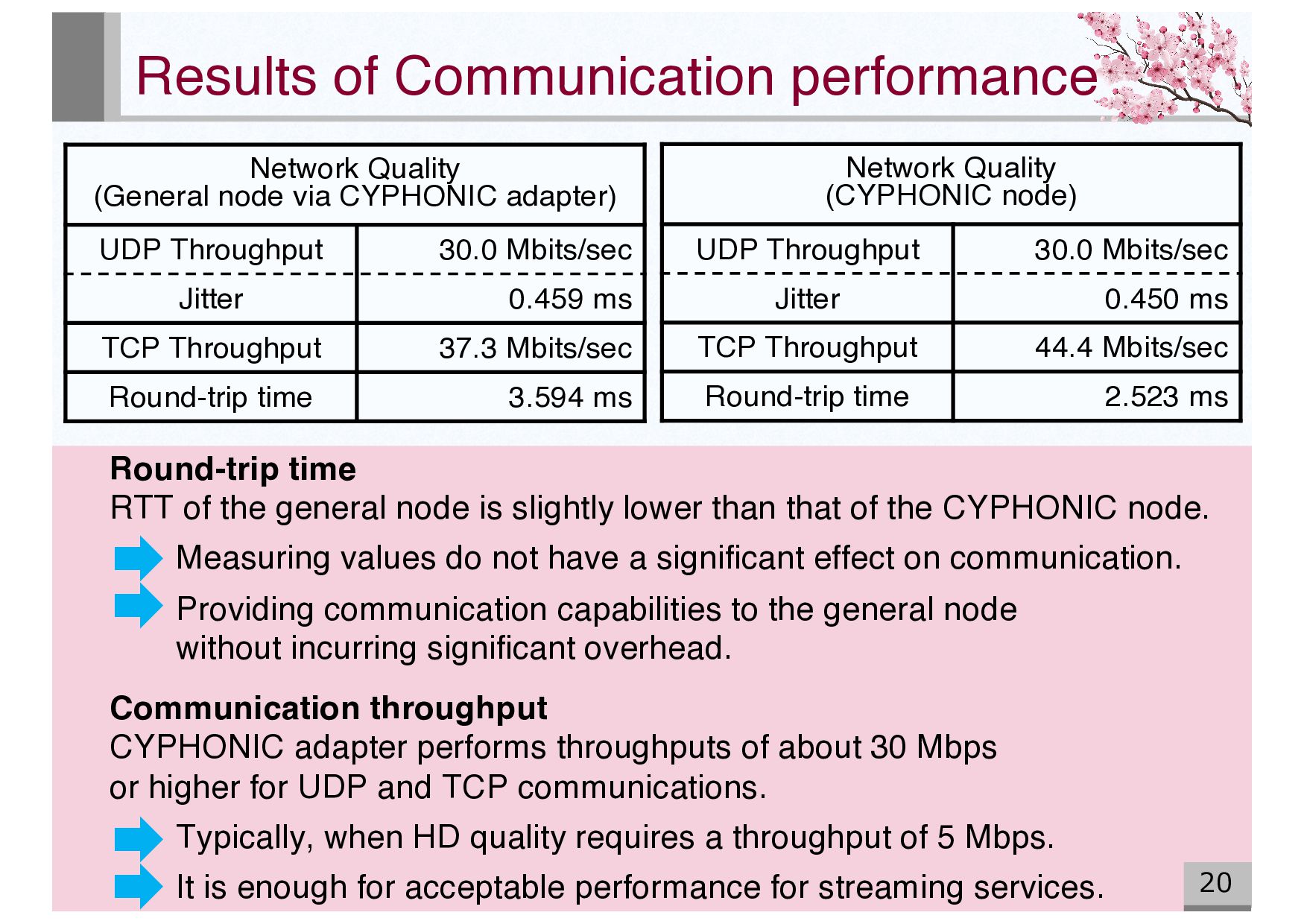
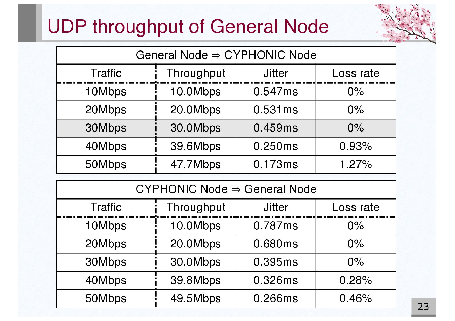
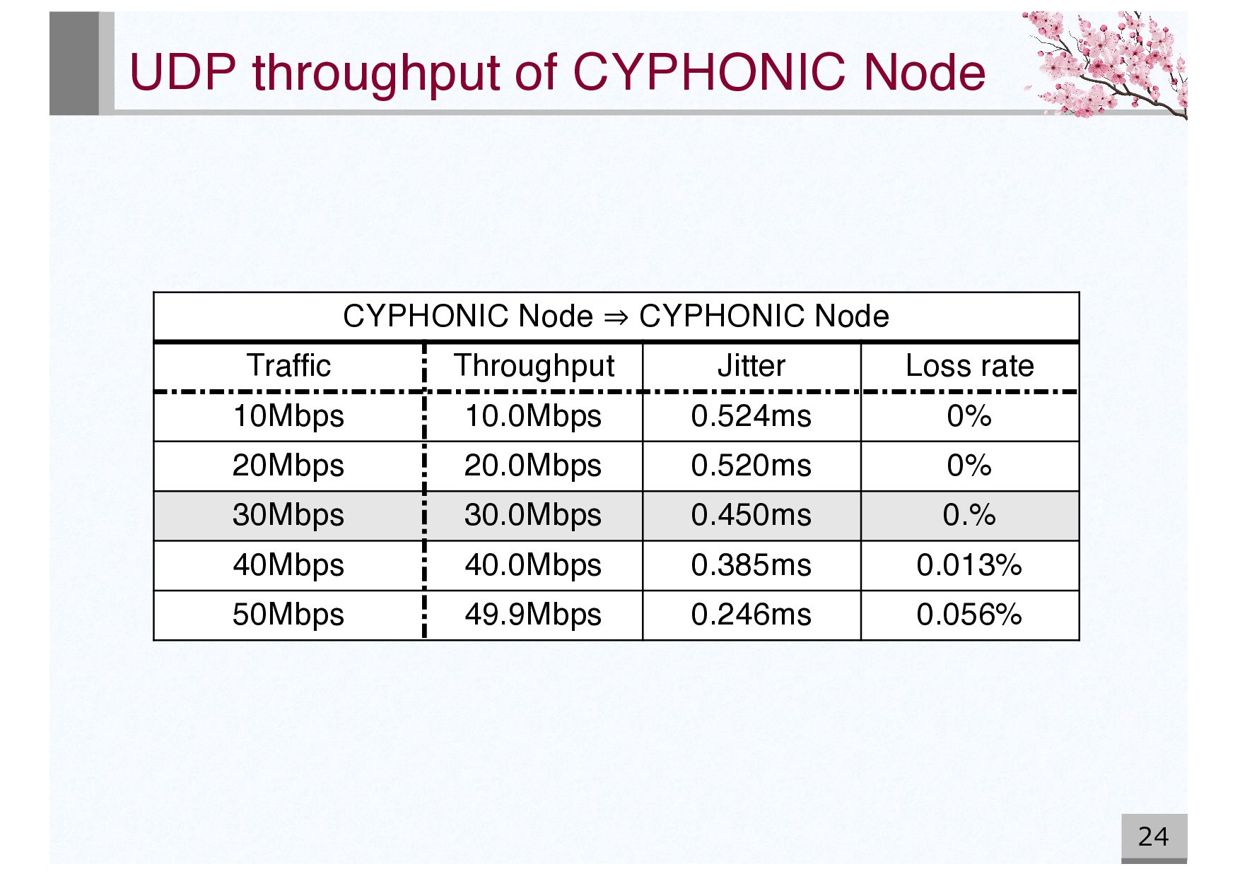
Throughput 30.0 Mbits/sec Jitter 0.450 ms TCP Throughput 44.4 Mbits/sec Round-trip time 2.523 ms Network Quality (General node via CYPHONIC adapter) UDP Throughput 30.0 Mbits/sec Jitter 0.459 ms TCP Throughput 37.3 Mbits/sec Round-trip time 3.594 ms Round-trip time RTT of the general node is slightly lower than that of the CYPHONIC node. Measuring values do not have a significant effect on communication. Providing communication capabilities to the general node without incurring significant overhead. Communication throughput CYPHONIC adapter performs throughputs of about 30 Mbps or higher for UDP and TCP communications. Typically, when HD quality requires a throughput of 5 Mbps. It is enough for acceptable performance for streaming services.
to perform processing for CYPHONIC communication instead of general nodes. Proposed system can provide communication capabilities to general nodes without incurring significant overhead 1. Equipping with the communication function of CYPHONIC. Utilizing the conventional functions of the device program as a communication function. 2. Equipping functions to manage on connected general nodes. Implementing additionally as the adapter’s unique functions.
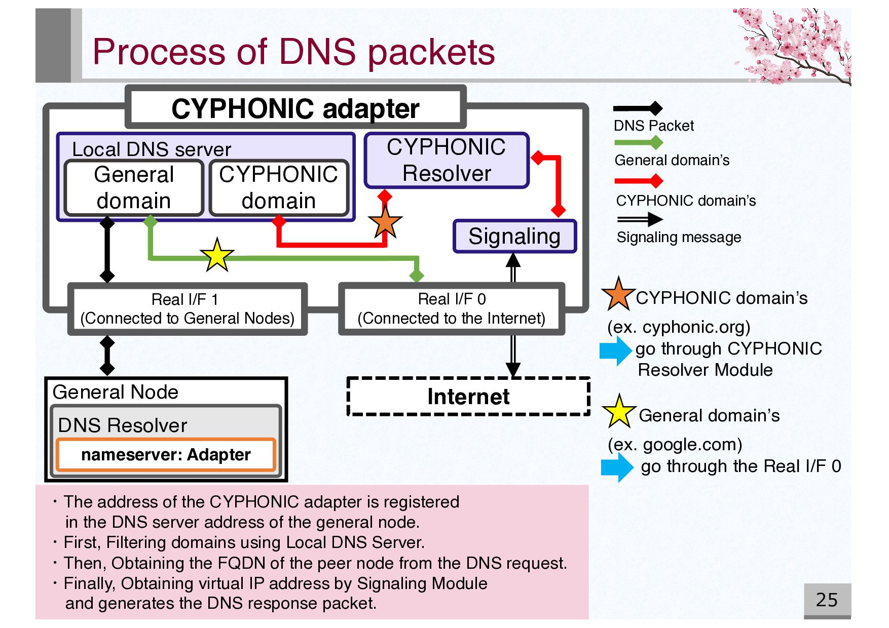
CYPHONIC domain’s (ex. cyphonic.org) go through CYPHONIC Resolver Module Process of DNS packets 25 CYPHONIC adapter CYPHONIC Resolver Local DNS server General domain CYPHONIC domain Signaling Real I/F 1 (Connected to General Nodes) nameserver: Adapter General Node DNS Resolver Internet ・The address of the CYPHONIC adapter is registered in the DNS server address of the general node. ・First, Filtering domains using Local DNS Server. ・Then, Obtaining the FQDN of the peer node from the DNS request. ・Finally, Obtaining virtual IP address by Signaling Module and generates the DNS response packet. Real I/F 0 (Connected to the Internet) Signaling message CYPHONIC domain’s DNS Packet General domain’s
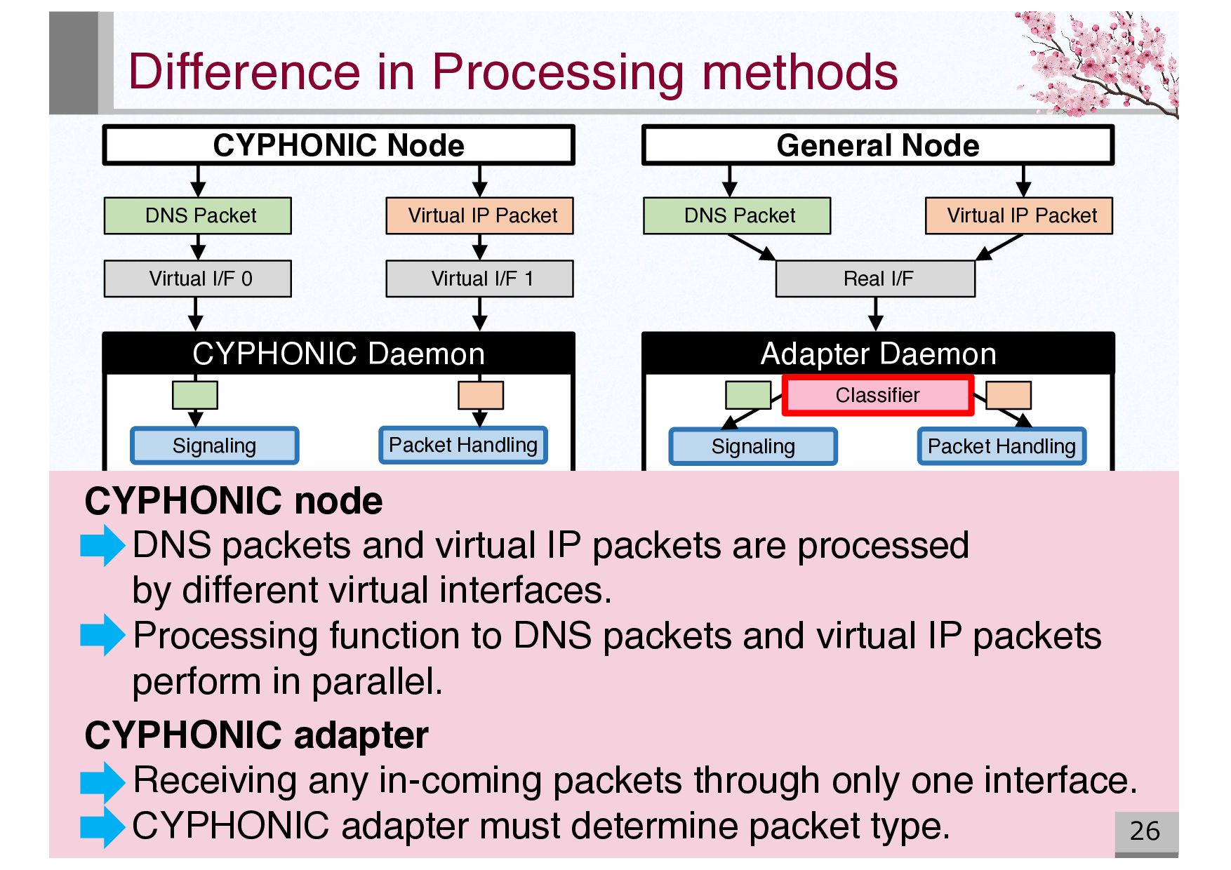
packets and virtual IP packets are processed by different virtual interfaces. Processing function to DNS packets and virtual IP packets perform in parallel. CYPHONIC adapter Receiving any in-coming packets through only one interface. CYPHONIC adapter must determine packet type. CYPHONIC Node General Node Virtual IP Packet DNS Packet Virtual I/F 0 Virtual I/F 1 Real I/F Signaling Signaling Packet Handling CYPHONIC Daemon Adapter Daemon DNS Packet Virtual IP Packet Classifier
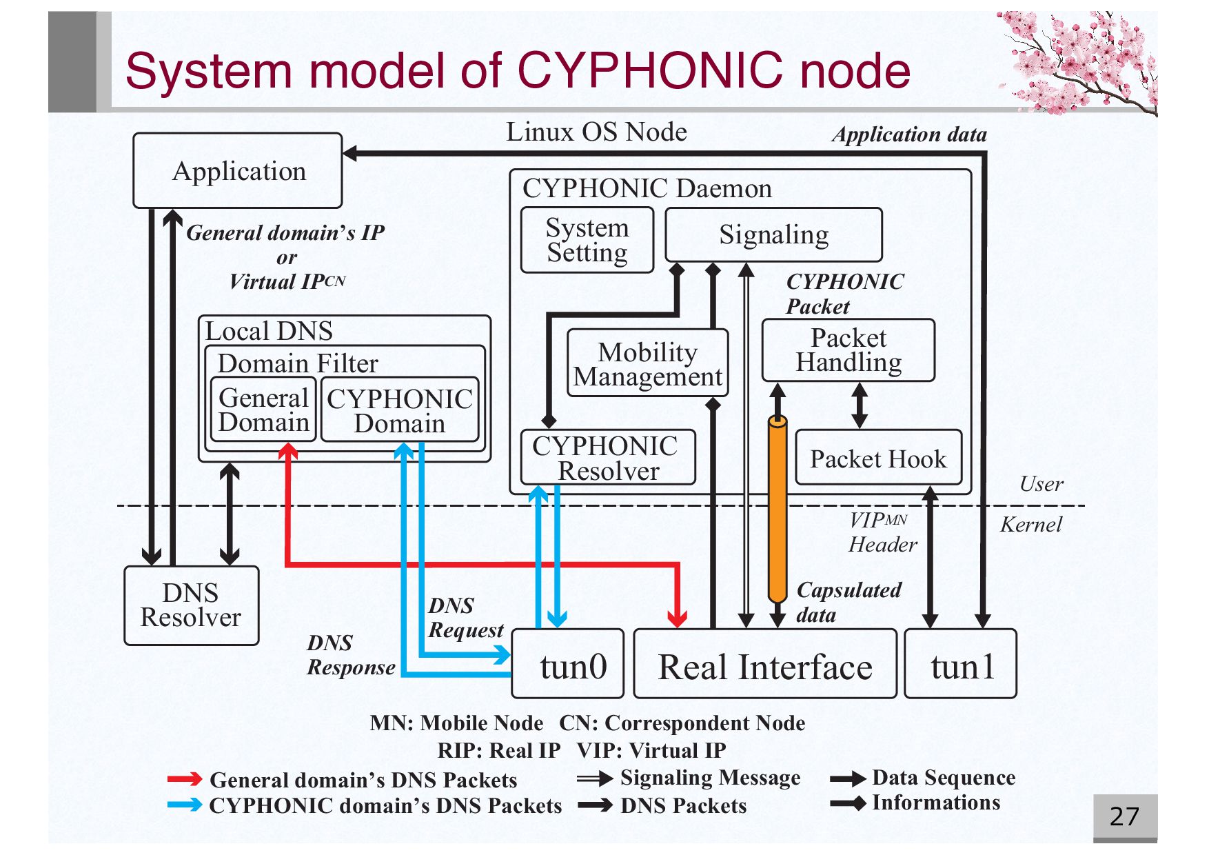
CYPHONIC Daemon CYPHONIC Packet General domain’s IP or Virtual IPCN Mobility Management System Setting CYPHONIC Resolver General Domain CYPHONIC Domain Domain Filter Local DNS Linux OS Node DNS Response User Kernel VIPMN Header DNS Request DNS Resolver Application CN: Correspondent Node MN: Mobile Node tun0 Application data tun1 Real Interface Informations CYPHONIC domain’s DNS Packets General domain’ s DNS Packets DNS Packets Data Sequence Signaling Message RIP: Real IP VIP: Virtual IP Capsulated data 27
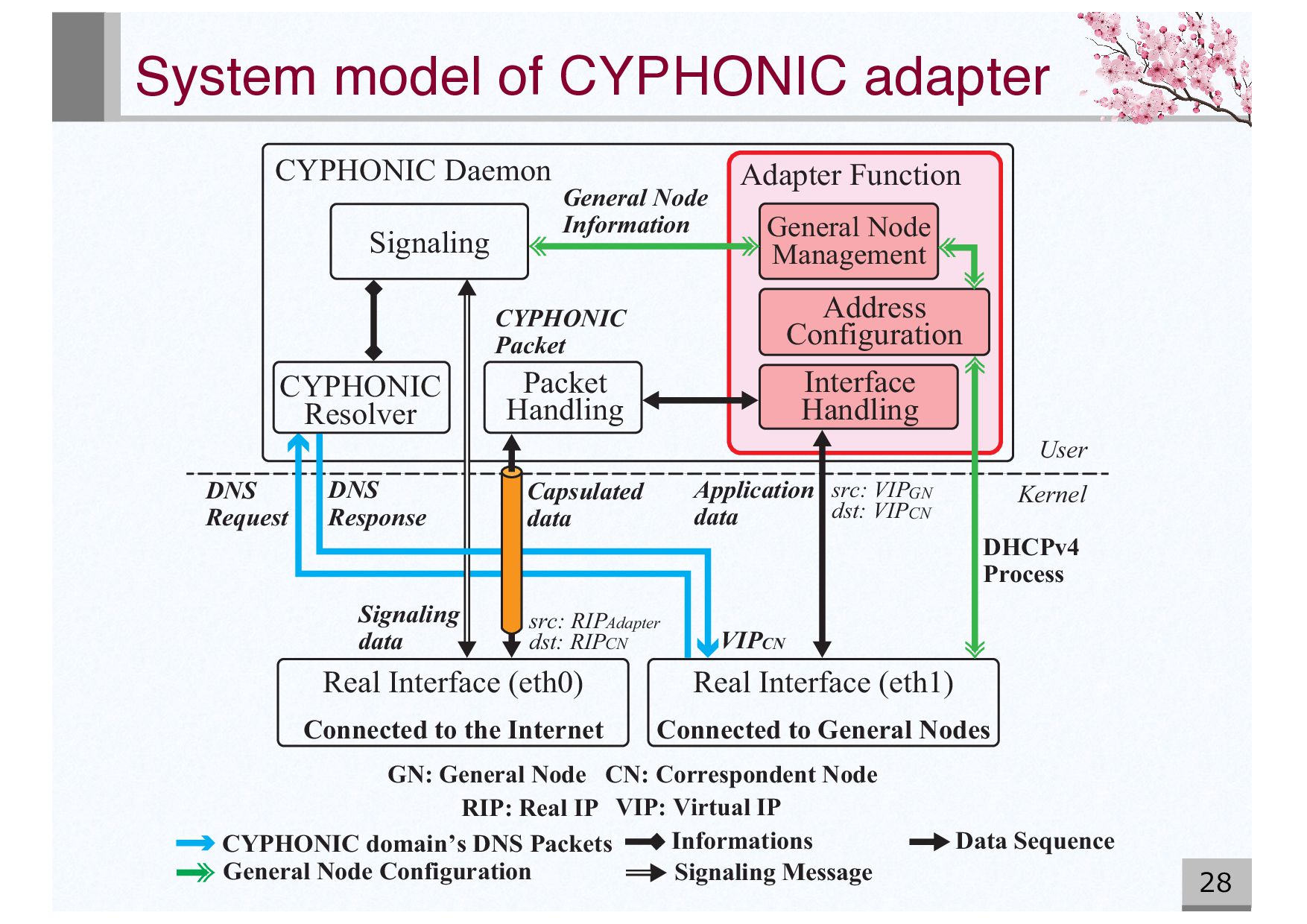
Node RIP: Real IP VIP: Virtual IP Adapter Function Interface Handling General Node Management General Node Information Address Configuration Real Interface (eth1) DNS Response Connected to General Nodes User Kernel DHCPv4 Process DNS Request Real Interface (eth0) Connected to the Internet Informations CYPHONIC domain’s DNS Packets Data Sequence Signaling Message General Node Configuration VIPCN CYPHONIC Resolver Packet Handling Signaling CYPHONIC Daemon Application data Signaling data Capsulated data CYPHONIC Packet src: RIP dst: RIP Adapter CN src: VIP dst: VIPCN GN 28
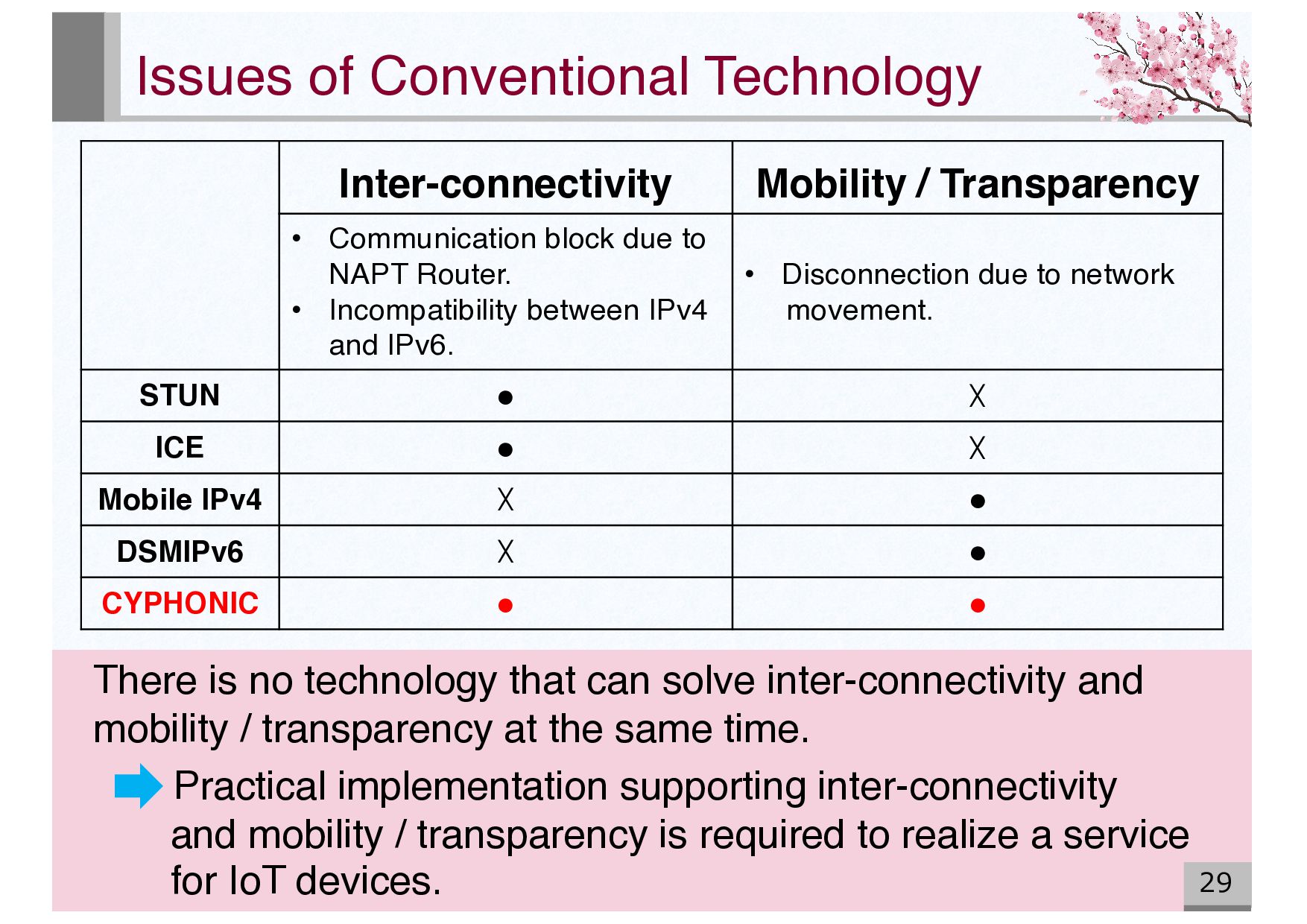
Communication block due to NAPT Router. • Incompatibility between IPv4 and IPv6. • Disconnection due to network movement. STUN • ☓ ICE • ☓ Mobile IPv4 ☓ • DSMIPv6 ☓ • CYPHONIC • • There is no technology that can solve inter-connectivity and mobility / transparency at the same time. Practical implementation supporting inter-connectivity and mobility / transparency is required to realize a service for IoT devices.
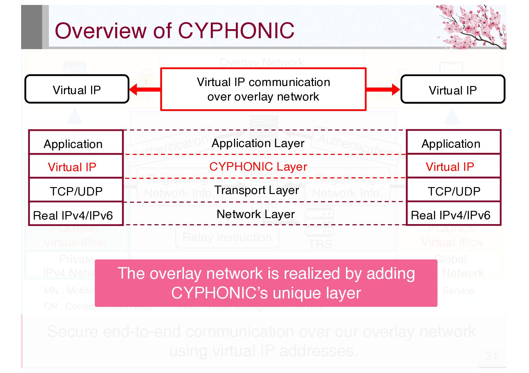
Correspondent Node NMS : Node Management Service AS : Authentication Service TRS : Tunnel Relay Service Private IPv4 Network Dual Stack Network AS NMS TRS MN CN FQDNMN Virtual IPMN FQDNCN 仮想IPアドレス Overlay Network Secure end-to-end communication Global IPv6 Network CN FQDNCN Virtual IPCN Authentication Authentication Registering Network Info. Registering Network Info. Relay instruction Secure end-to-end communication over our overlay network using virtual IP addresses. CYPHIO The overlay network is realized by adding CYPHONIC’s unique layer Application Real IPv4/IPv6 Virtual IP TCP/UDP Application Real IPv4/IPv6 Virtual IP TCP/UDP CYPHONIC Layer Application Layer Transport Layer Network Layer Virtual IP Virtual IP communication over overlay network Virtual IP
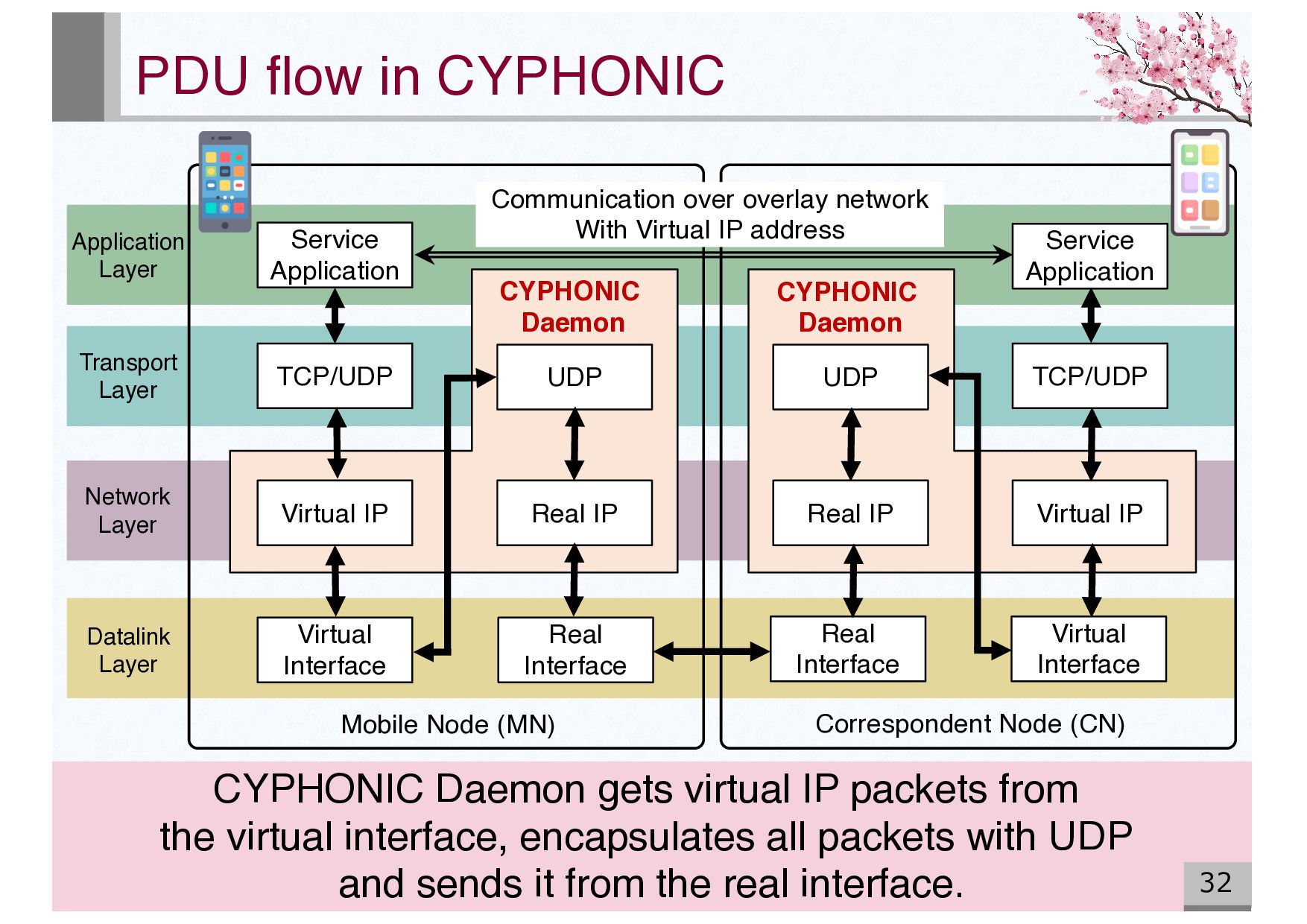
Real Interface Real IP UDP UDP Real IP Virtual IP Real Interface Virtual Interface TCP/UDP Service Application Communication over overlay network With Virtual IP address Virtual IP CYPHONIC Daemon CYPHONIC Daemon Mobile Node (MN) Correspondent Node (CN) Application Layer Transport Layer Network Layer Datalink Layer CYPHONIC Daemon gets virtual IP packets from the virtual interface, encapsulates all packets with UDP and sends it from the real interface.
Login Request Login Response SSL/TLS SSL/TLS AS MN DB First, authenticating MN. (ID&password, Digital certificate, SSO) Then, generating the common key to be used in communication between MN and NMS and store it in the DB. Finally, sending the common key used for communication between MN and NMS.
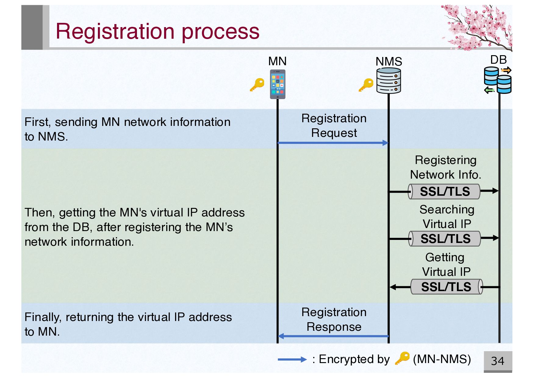
Searching Virtual IP SSL/TLS Getting Virtual IP NMS Registration Request Registration Response : Encrypted by (MN-NMS) First, sending MN network information to NMS. Then, getting the MN's virtual IP address from the DB, after registering the MN’s network information. Finally, returning the virtual IP address to MN.
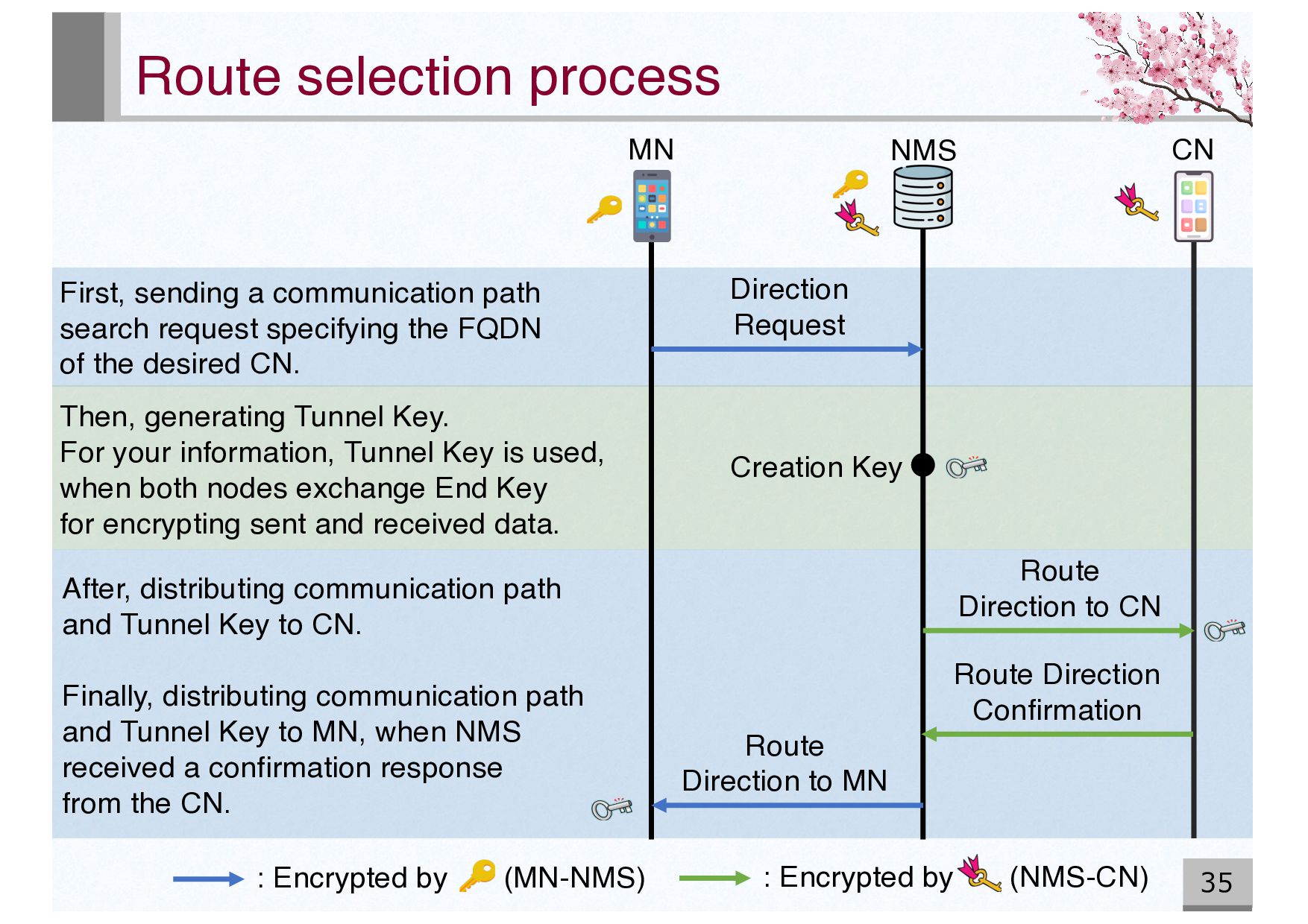
CN Direction Request Route Direction to MN Creation Key Route Direction to CN Route Direction Confirmation : Encrypted by (MN-NMS) Then, generating Tunnel Key. For your information, Tunnel Key is used, when both nodes exchange End Key for encrypting sent and received data. First, sending a communication path search request specifying the FQDN of the desired CN. After, distributing communication path and Tunnel Key to CN. Finally, distributing communication path and Tunnel Key to MN, when NMS received a confirmation response from the CN.
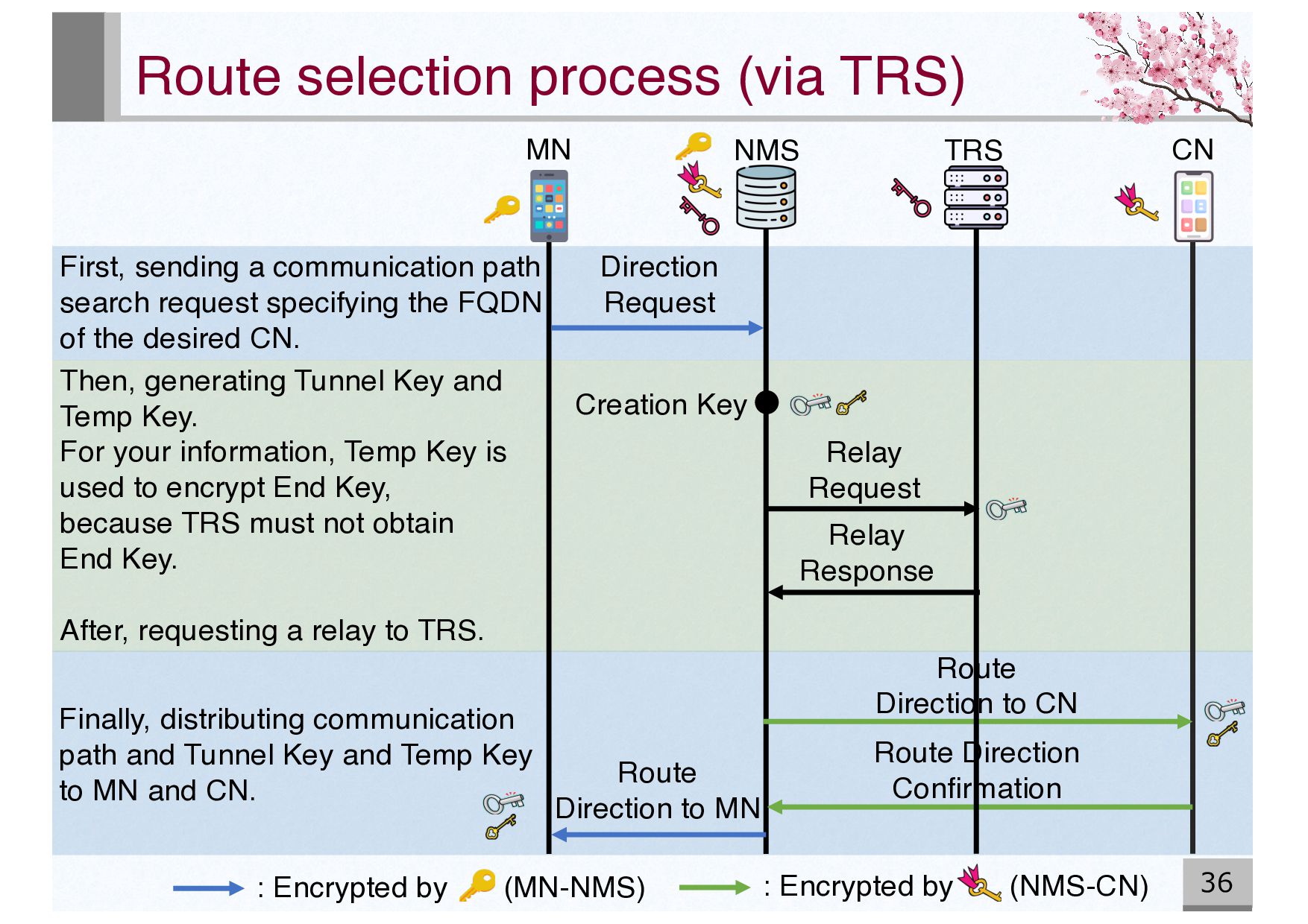
Direction to MN Creation Key Route Direction Confirmation TRS Direction Request Relay Request Relay Response Route Direction to CN : Encrypted by (MN-NMS) : Encrypted by (NMS-CN) First, sending a communication path search request specifying the FQDN of the desired CN. Then, generating Tunnel Key and Temp Key. For your information, Temp Key is used to encrypt End Key, because TRS must not obtain End Key. After, requesting a relay to TRS. Finally, distributing communication path and Tunnel Key and Temp Key to MN and CN.
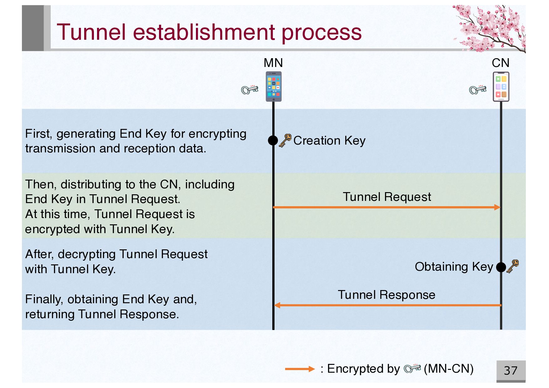
Tunnel Response : Encrypted by (MN-CN) Obtaining Key After, decrypting Tunnel Request with Tunnel Key. Finally, obtaining End Key and, returning Tunnel Response. Then, distributing to the CN, including End Key in Tunnel Request. At this time, Tunnel Request is encrypted with Tunnel Key. First, generating End Key for encrypting transmission and reception data.
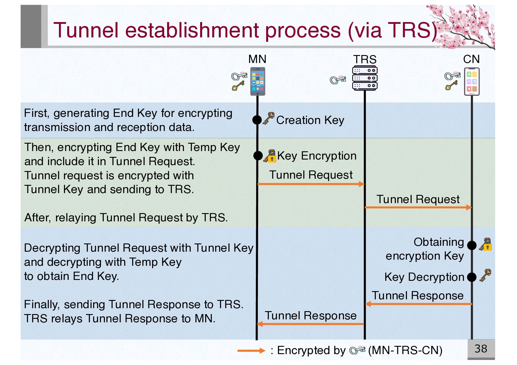
Key Key Encryption Tunnel Request Tunnel Request Key Decryption Tunnel Response Tunnel Response Obtaining encryption Key : Encrypted by (MN-TRS-CN) Decrypting Tunnel Request with Tunnel Key and decrypting with Temp Key to obtain End Key. Finally, sending Tunnel Response to TRS. TRS relays Tunnel Response to MN. Then, encrypting End Key with Temp Key and include it in Tunnel Request. Tunnel request is encrypted with Tunnel Key and sending to TRS. After, relaying Tunnel Request by TRS. First, generating End Key for encrypting transmission and reception data.