Upgrade to Pro — share decks privately, control downloads, hide ads and more …

Bus Protocols Explained - Parallel, '232, I2C, SPI

Bus Protocols Explained - Parallel, '232, I2C, SPI

In order to connect devices (e.g. RGB LED, temperature sensor, ...) to your microcontroller (e.g. Arduino, ARM board, ESP8266), you'll need to use some kind of bus. Come and learn about how some common types of bus work. I'll cover at least I2C and SPI, and perhaps others such as RS-232, parallel, etc.

Understanding how these buses work isn't always strictly necessary in order to use them, but it will help out when you want to:

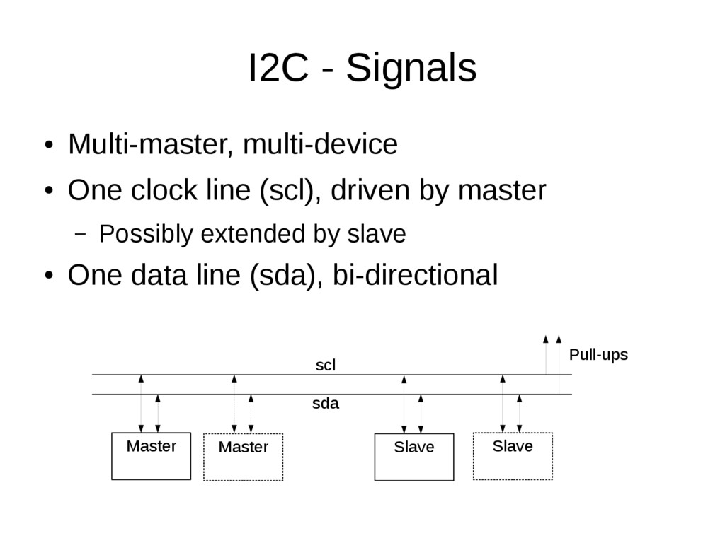
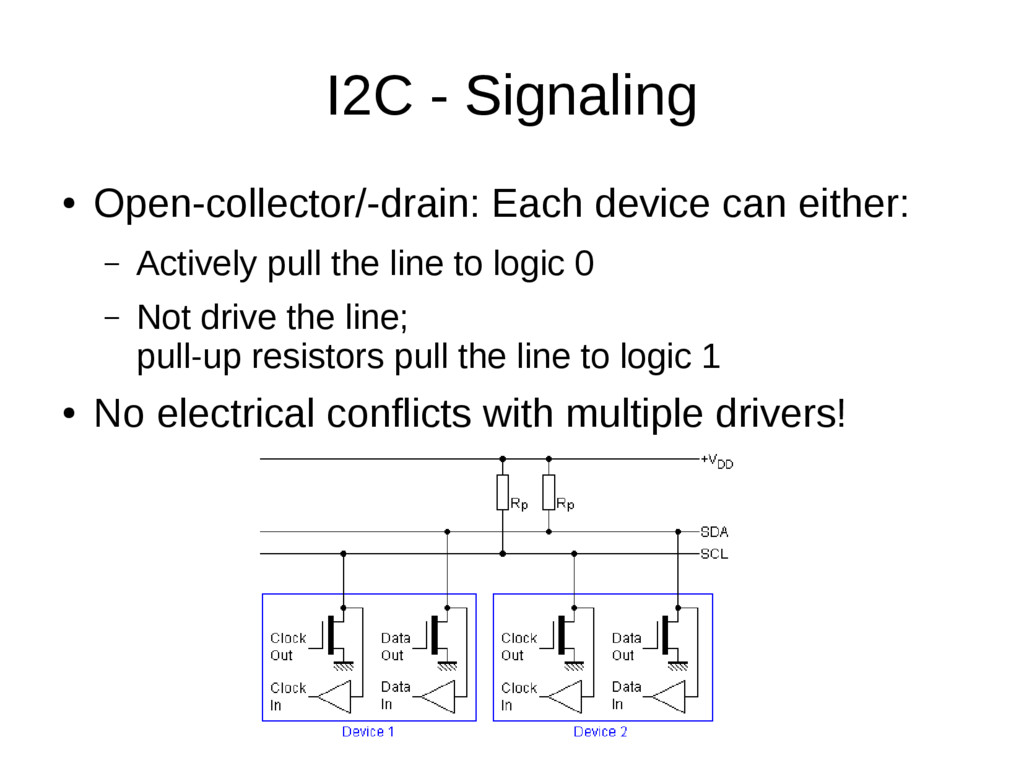
• Work out how to connect your device to your micro-controller electrically.

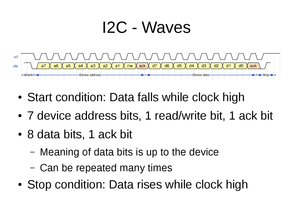
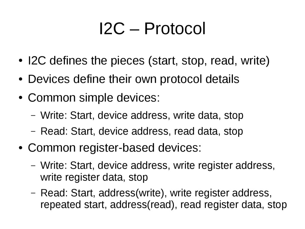
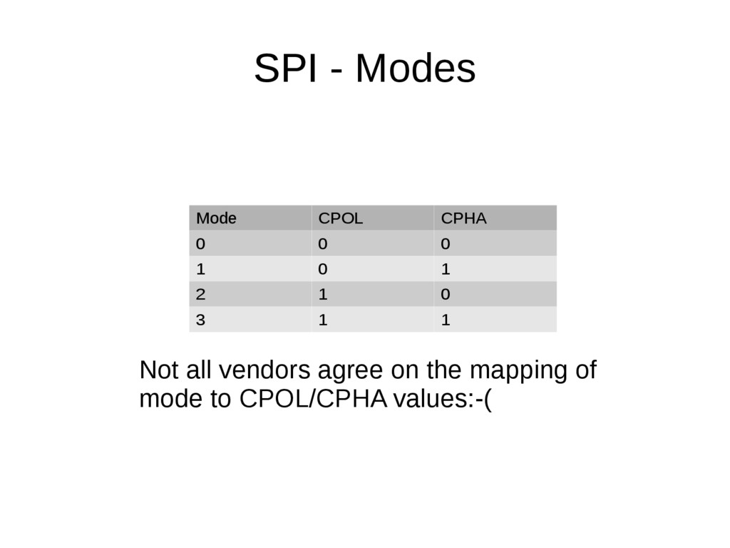
• Understand what information you'll need in order to write code to communicate with your device, e.g. what's an "I2C address", or an "SPI chip select"?

• Debug why your system isn't working, using an oscilloscope or logic analyzer.

• You want a deeper understanding of the systems you're building, in the maker spirit.

Stephen Warren

January 07, 2016
Tweet

More Decks by Stephen Warren

Other Decks in Programming

Transcript

  1. Contents • Brief discussion of binary • Parallel bus •

    RS-232/EIA-232 (serial) • I2C • SPI
  2. Binary vs. Decimal • What is binary? – Simply another

    way to represent numbers – Math works exactly the same • Decimal uses 10 values for digits; 0..9 – Numbers are represented as a sum of powers of 10 – 905 10 (9 × 10²) + (0 × 101) + (5 × 100) • Binary uses 2 values for digits, 0..1 – Numbers are represented as a sum of powers of 2 – 101 2 (1 × 22) + (0 × 21) + (1 × 20) i.e. 5 10
  3. Binary – Use In Circuits • Signals in (most) digital

    circuits have two states: – On/off, high/low, 1/0 • This maps perfectly to binary math: – Binary allows only two values for any digit – 1 and 0 • Circuits use a fixed number of digits per number – Binary digit == “bit” – Each binary digit is a single wire/signal in the circuit – Using 8 bits (1 byte) is common, e.g. files, ASCII, …
  4. Binary Examples • 00000000 2 = 0 10 • 00000001

    2 = 1 10 • 00000010 2 = 2 10 • 10100110 2 = 166 10 • 11111111 2 = 255 10
  5. Simple Parallel Port - Signals • Used by (older) printers

    • More complex variants are possible – Address, read-vs-write, wait/busy, … – Other uses: Memory bus, PCI, ... Master Slave data strobe (ground connection is implicit in all diagrams) 8 bits
  6. Simple Parallel Port - Waves d[7:0] H e l l

    o strobe • Data sent via 8 wires/signals (“d[7:0]” above) – 8 bits/wires/signals are sent at once “in parallel” – Together they represent a single number/character • Strobe signal pulses once for each byte – Receiver captures data on falling edge of strobe
  7. RS-232/EIA-232 - Signals • Data is “serialized” onto a single

    signal • Asynchronous; no clock or strobe signal – Start and Stop bits used for sync; see waves • Bi-directional – Independent communication in each direction Device A Device B txd rxd rxd txd (also, rts, cts, dsr, dtr, dcd, ri, … which we don't cover)
  8. RS-/EIA-232 – (TTL) Waves txd d0 d1 d2 d3 d4

    d5 d6 d7 start data byte stop a b c d • Idle state is “1” • 1 start bit • 5, 6, 7, or 8 data bits sent serially LSB first • Odd/even/mark/space parity bit (or none) • 1, 1.5, or 2 stop bits
  9. RS/EIA-232 – Baud Rate • Each bit takes a fixed

    time to transmit • The transmitter and receiver must agree on the time taken for each bit • The baud rate is the measurement of this time – Counted in terms of bits per second, e.g. 115200 – Defines how many bits fit into each second, and hence the time taken by each bit • Max data rate is slightly less than the baud rate
  10. RS/EIA-232 – Voltage Levels • TTL and true RS-232 use

    different voltages, but the same protocol • TTL: a 0 is 0V, a 1 is e.g. 1.8V, 3.3V, 5V • RS-232: Depending on what you read: – 0 is at least +3V, perhaps up to +25V – 1 is at least -3V, perhaps down to -25V – Commonly quoted as ±12V
  11. RS/EIA-232 – Receiver Sync • No clock; receiver must sync

    to incoming signal • RX typically samples using clock running at 16x baud rate to align to beginning of start bit • Start bit re-sampled 8 clocks later • Each bit sampled at 16 clocks later • Start, parity, stop bits validated before accepting character txd d0 d1 d2 d3 d4 d5 d6 d7 start data byte stop a b c d
  12. I2C Inter-IC Protocol – IIC – I2C a/k/a TWI –

    Two Wire Interface http://www.i2c-bus.org/
  13. I2C - Signals • Multi-master, multi-device • One clock line

    (scl), driven by master – Possibly extended by slave • One data line (sda), bi-directional Master Slave Master Slave scl sda Pull-ups
  14. I2C - Signaling • Open-collector/-drain: Each device can either: –

    Actively pull the line to logic 0 – Not drive the line; pull-up resistors pull the line to logic 1 • No electrical conflicts with multiple drivers!
  15. I2C - Waves scl sda a7 a6 a5 a4 a3

    a2 a1 r/w ack d7 d6 d5 d4 d3 d2 d1 d0 ack Start Device address Device data Stop a b c d e • Start condition: Data falls while clock high • 7 device address bits, 1 read/write bit, 1 ack bit • 8 data bits, 1 ack bit – Meaning of data bits is up to the device – Can be repeated many times • Stop condition: Data rises while clock high
  16. I2C – Protocol • I2C defines the pieces (start, stop,

    read, write) • Devices define their own protocol details • Common simple devices: – Write: Start, device address, write data, stop – Read: Start, device address, read data, stop • Common register-based devices: – Write: Start, device address, write register address, write register data, stop – Read: Start, address(write), write register address, repeated start, address(read), read register data, stop
  17. I2C – Clock Rate • I2C originally used 100KHz clock

    rate (max) – Masters or slaves can use/force a slower speed • Protocol revisions allow for 400KHz, or even 3.4MHz clock rates – This allows faster data transfer – The bus can run only as fast as the clock rate supported by the slowest attached device
  18. I2C – Clock Stretching http://www.i2c-bus.org/i2c-primer/clock-generation-stretching-arbitration/ • Master pulses the clock

    to drive the transaction • When the clock is low, the device can “stretch” the clock by pulling it low too • The master will notice this, and wait until the device releases the clock • This allows slow slaves to operate at the clock speed they wish • Also could be used to delay a response until slave device can answer master's request
  19. I2C – Multi-Master http://www.i2c-bus.org/i2c-primer/clock-generation-stretching-arbitration/ • Any master can start a

    transaction when the bus is idle • If no other master starts at the same time, the transaction simply operates as expected • If multiple masters start at once, some master sees the bus in a different state than it is transmitting • That master simply aborts its transaction and lets the other master keep going – The transaction can be retried once the bus is idle
  20. I2C – Repeated Start http://www.i2c-bus.org/repeated-start-condition/ • Bus is idle between

    stop and start • Master can lose bus ownership (arbitration) when idle • Can be a problem for register reads – This takes two separate I2C transactions – Register address could be corrupted by another master • Generate a repeated start to solve this – (Generate a start without a stop first; bus never idle) scl sda scl sda Stop Idle Start a b c d
  21. I2C – 10-bit Addressing http://www.i2c-bus.org/addressing/10-bit-addressing/ • 7 bits of address

    isn't that much • Can have address collisions between devices – Devices often can be configured to 1 of n addresses – Doesn't solve all problems • Some devices can use 10 bits for the address to help avoid collisions (split over 2 bytes) • Some of the 7-bit patterns indicate an extra address byte follows – No 7-bit device will respond to those patterns
  22. SPI - Signals • Single-master, multi-slave (chip-/slave-selects) • Master drives

    clock • Read and write use separate wires – Master In Slave Out / Master Out Slave In Master miso mosi clk Slave Slave cs/ss
  23. SPI - Waves sck mosi d7 d6 d5 d4 d3

    d2 d1 d0 e7 e6 e5 e4 e3 e2 e1 e0 miso f7 f6 f5 f4 f3 f2 f1 f0 g7 g6 g5 g4 g3 g2 g1 g0 byte 0 byte 1 a b c • Rising clock: Both master and slave send data • Falling clock: Both receive a data bit too • Data typically framed into bytes – By counting clocks/bits since start of transaction • 100% of the meaning of data is defined by the slave device, not by SPI itself
  24. SPI with Chip Select - Waves sck mosi d7 d6

    d5 e2 e1 e0 f7 f6 f5 g2 g1 g0 miso h7 h6 h5 j2 j1 j0 k7 k6 k5 m2 m1 m0 cs0 cs1 access dev 0 access dev 1 a | b c d • Addition of chip-/slave-select signals allows multi-slave operation • Each slave receives MOSI and drives MISO only when its own chip select is active
  25. SPI - Modes • Clock polarity can differ: – Referred

    to as CPOL – 0: Clock is 0 at idle, rises and falls for each bit – 1: Clock is 1 at idle, falls and rises for each bit • Clock phase can differ: – Referred to as CPHA – 0: First edge: send data, second edge: receive data – 1: First edge: receive data, second edge: send data • Together, these define the “mode”
  26. SPI - Modes SCK CPOL=0 CPOL=1 SS Cycle # 2

    3 4 5 6 7 8 1 MISO 2 3 4 5 6 7 8 z z 1 MOSI 2 3 4 5 6 7 8 z z 1 CPHA=1 CPHA=0 Cycle # 1 2 3 4 5 6 7 8 MISO 1 2 3 4 5 6 7 8 z z 1 2 3 4 5 6 7 8 z MOSI z https://commons.wikimedia.org/wiki/File:SPI_timing_diagram2.svg
  27. SPI - Modes Mode CPOL CPHA 0 0 0 1

    0 1 2 1 0 3 1 1 Not all vendors agree on the mapping of mode to CPOL/CPHA values:-(
  28. SPI – Clock Rates • Clock is driven by master;

    master sets rate • No clock stretching • Each slave can only withstand a certain maximum clock rate • The chosen clock must satisfy every slave's requirements re: maximum rate
  29. Voltage • Each device operates at some voltage • For

    I2C, SPI, the voltage is set by the device, not the protocol definition • 5V, 3.3V, even 1.8V are common • Make sure your devices and controller are all compatible! • Level shifters can let you mix/match devices
  30. Bit-Banging • Dedicated controllers make protocols easy • Some micro-controllers/CPUs/SoCs/...

    don't support the protocol you want, or don't have enough controllers • You might need to “bit-bang” the protocol • That is: write software to read/write GPIO pins to emulate the protocol • Typically data rates are lower when bit-banging, due to software overhead
  31. Other Protocols • WS2812 RGB LEDs • OneWire, CAN, infra-red

    (remote control), ... • Custom protocols • Common themes across all protocols • Interrupts (out-of-band attention requests)