too heavy – Plenty of opportunity for follow-on presentations or hands-on coaching • Practical familiarity with components – Pick them up and look at them a bit later • Practical experimentation – Hopefully you'll get an intuitive feel for what the components do
electrical current can flow (What's current? Next page...) • The loop will contain various components (We'll describe some examples later...) • Can be a complex network of loops, not just one simple loop
a circuit – Those charge carriers are typically electrons – Similar to the flow of water in a pipe • Measured in Amperes/Amps (A) – LEDs or micro-controllers use tens of mA – Consumer electronics use (order of) ~1-2A – Home appliances use (order of) 10-50A – Just a few mA can kill you! • Depending on voltage and other factors • Don't worry – low voltages are safe
Sounds complicated! – Potential: cf. gravitational potential energy due to height differences in a hydro-electric dam • Think of it as the force pushing current – Similar to pressure in a water pipe, • Measured in Volts (V). Typical values: – 5V for electronics (safe to tinker with) – 12V for car batteries – 100-250V for household mains (don't play with this) – Perhaps 2000kV for grid transmission lines (stay well away)
at one voltage to areas of another voltage • This is a change in the (electric) potential energy of the charge carriers • The gained or lost energy can be converted to/from other forms, e.g. light, heat, motion – This is how electronics interfaces with the world
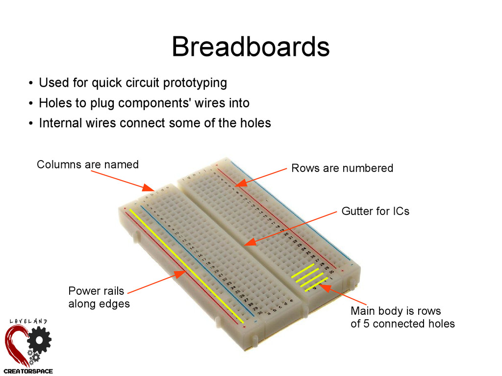
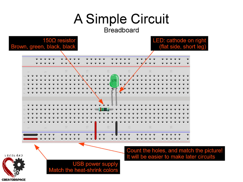
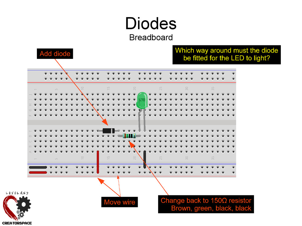
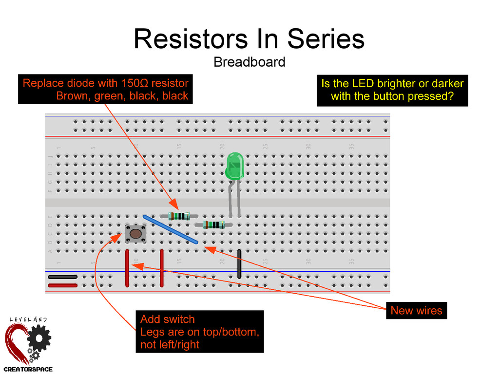
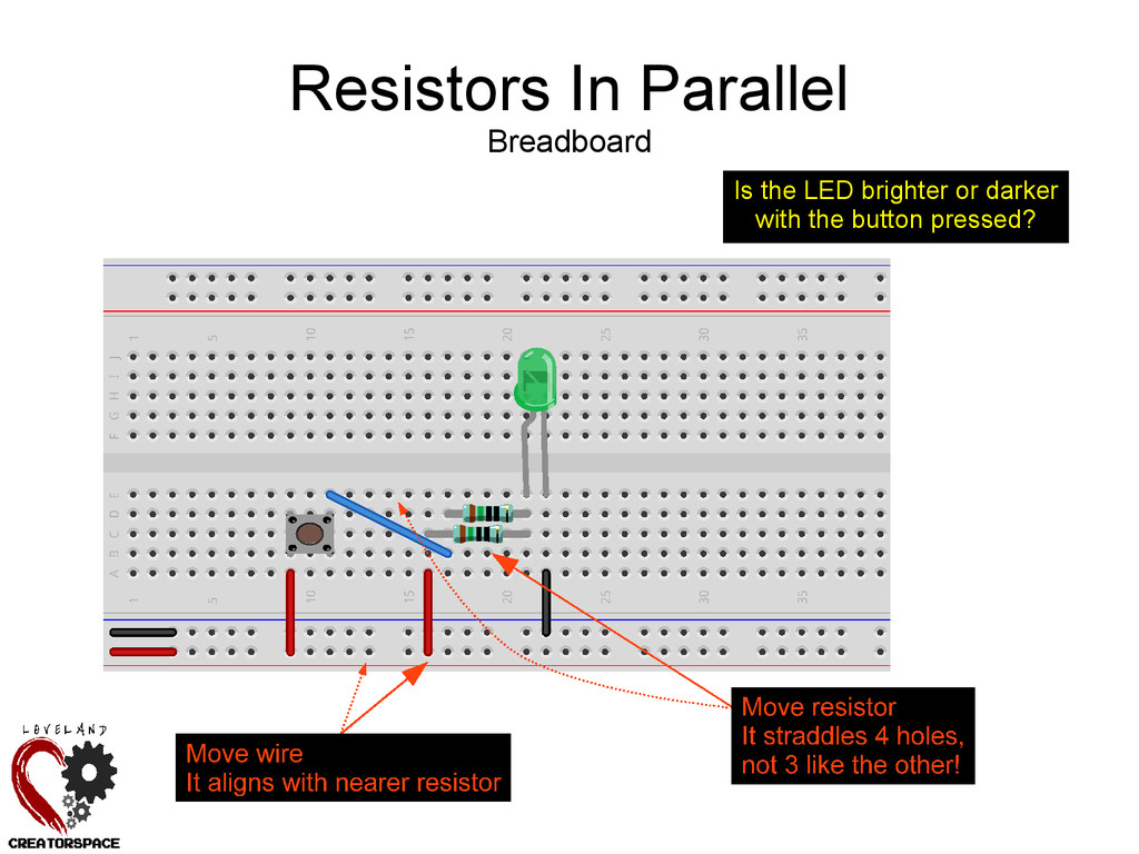
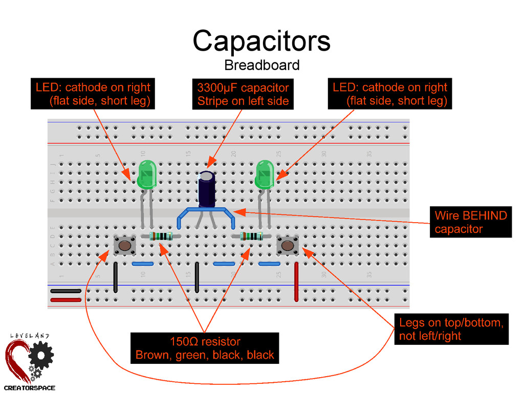
components' wires into • Internal wires connect some of the holes Breadboards Power rails along edges Main body is rows of 5 connected holes Rows are numbered Columns are named Gutter for ICs
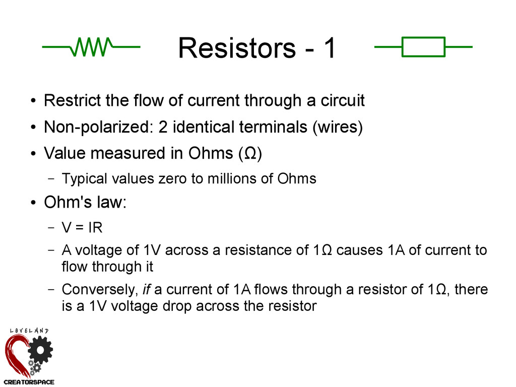
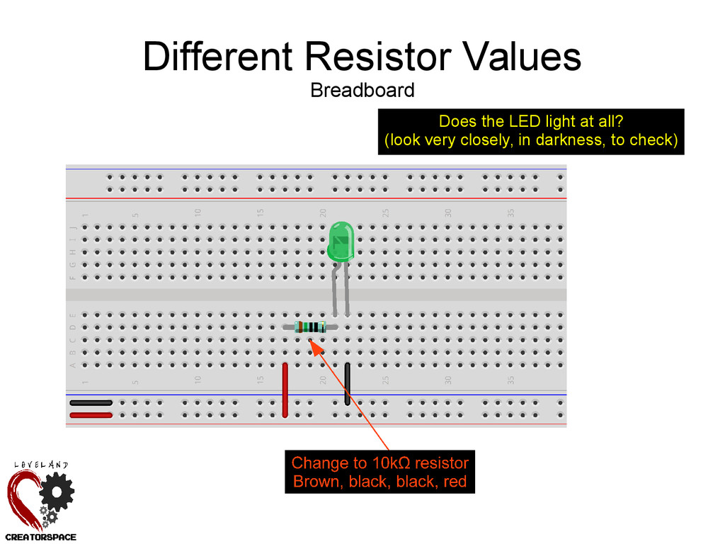
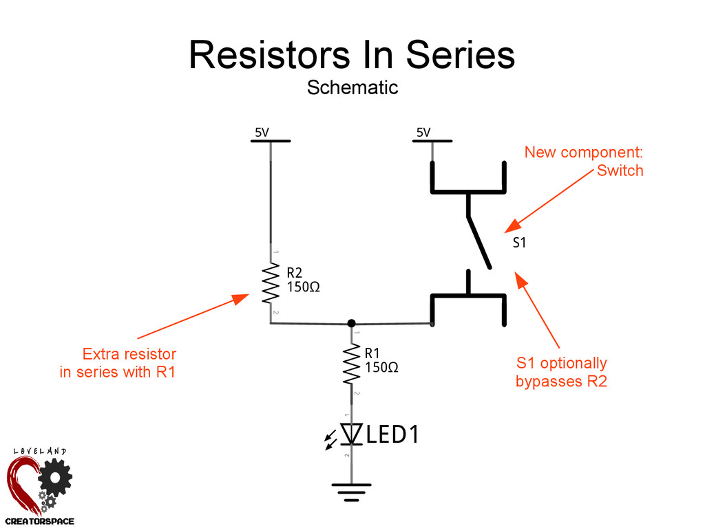
a circuit • Non-polarized: 2 identical terminals (wires) • Value measured in Ohms (Ω) – Typical values zero to millions of Ohms • Ohm's law: – V = IR – A voltage of 1V across a resistance of 1Ω causes 1A of current to flow through it – Conversely, if a current of 1A flows through a resistor of 1Ω, there is a 1V voltage drop across the resistor
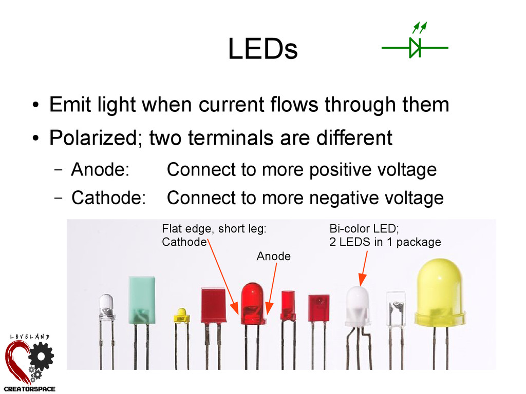
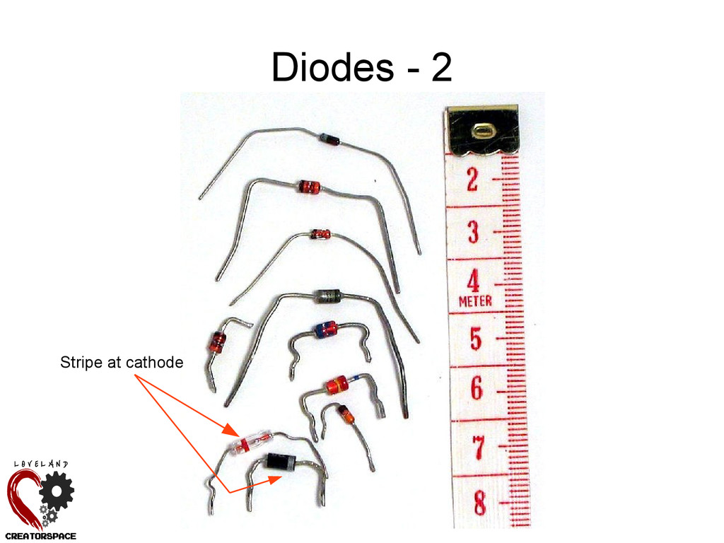
Polarized; two terminals are different – Anode: Connect to more positive voltage – Cathode: Connect to more negative voltage Flat edge, short leg: Cathode Anode Bi-color LED; 2 LEDS in 1 package
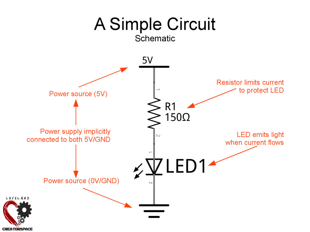
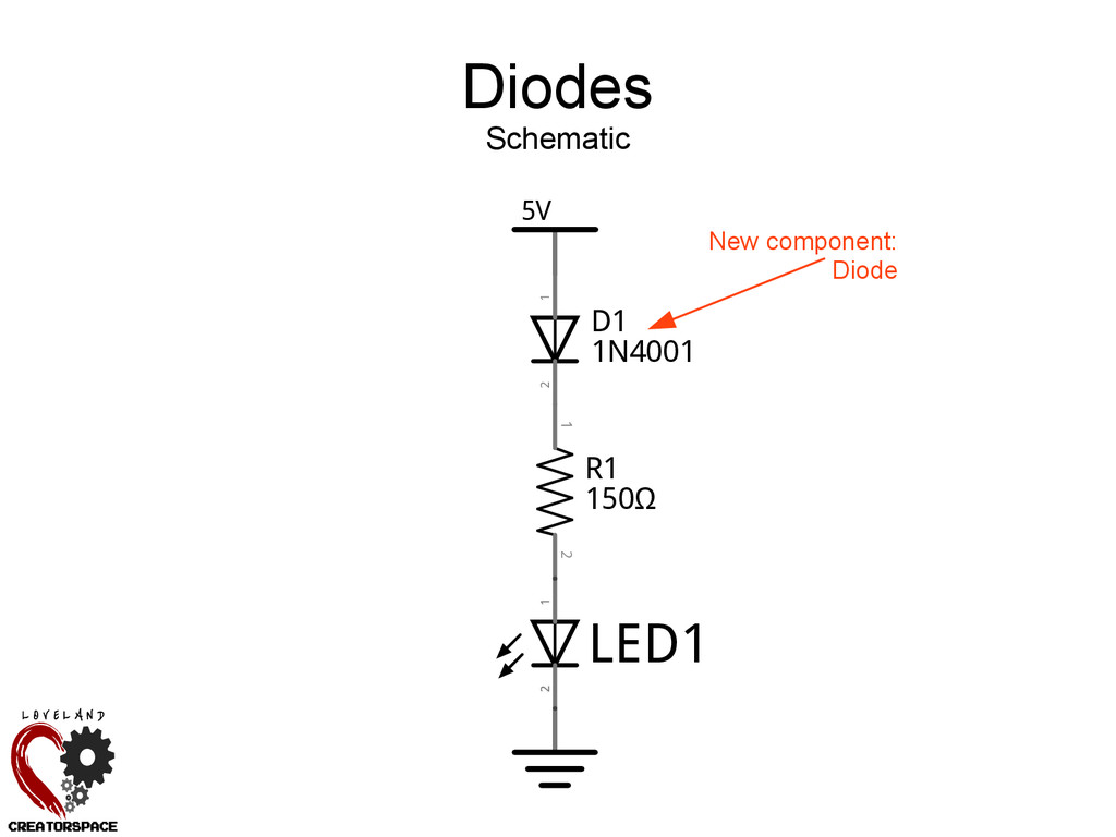
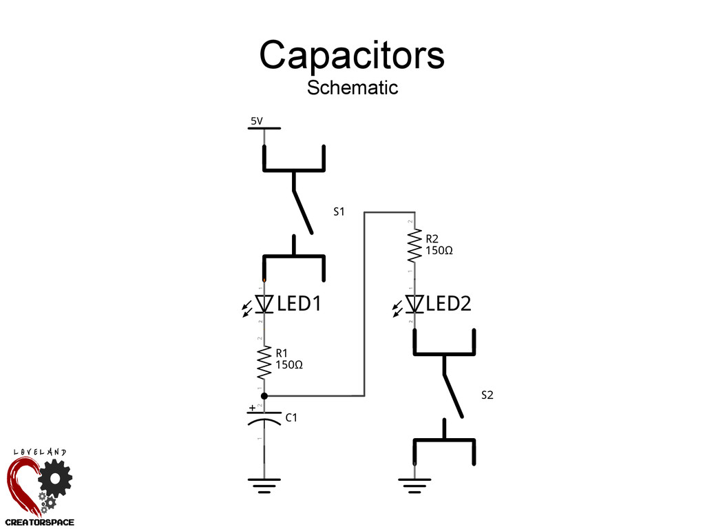
Power source (5V) Power source (0V/GND) LED emits light when current flows Resistor limits current to protect LED Power supply implicitly connected to both 5V/GND
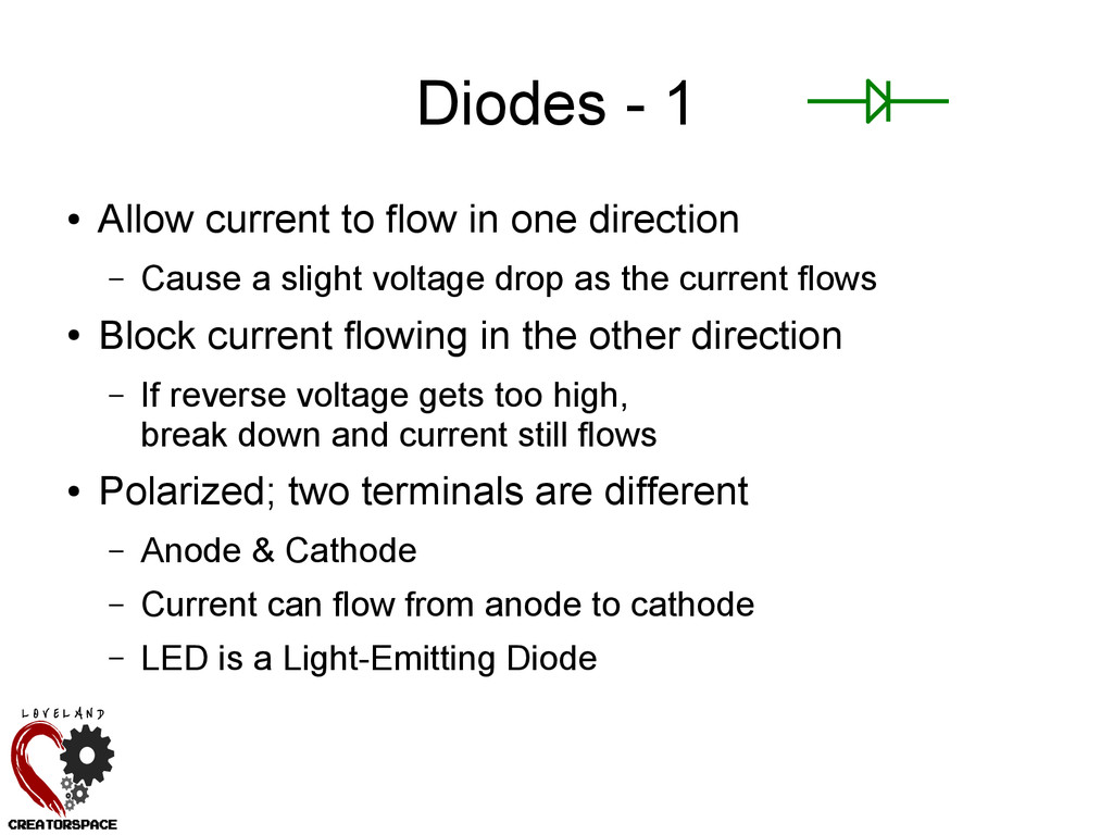
direction – Cause a slight voltage drop as the current flows • Block current flowing in the other direction – If reverse voltage gets too high, break down and current still flows • Polarized; two terminals are different – Anode & Cathode – Current can flow from anode to cathode – LED is a Light-Emitting Diode
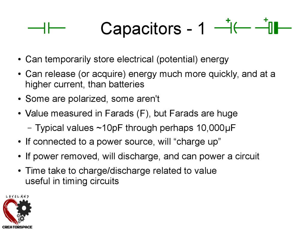
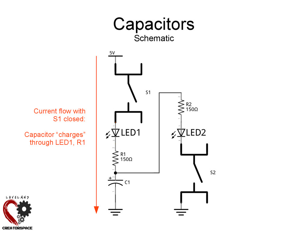
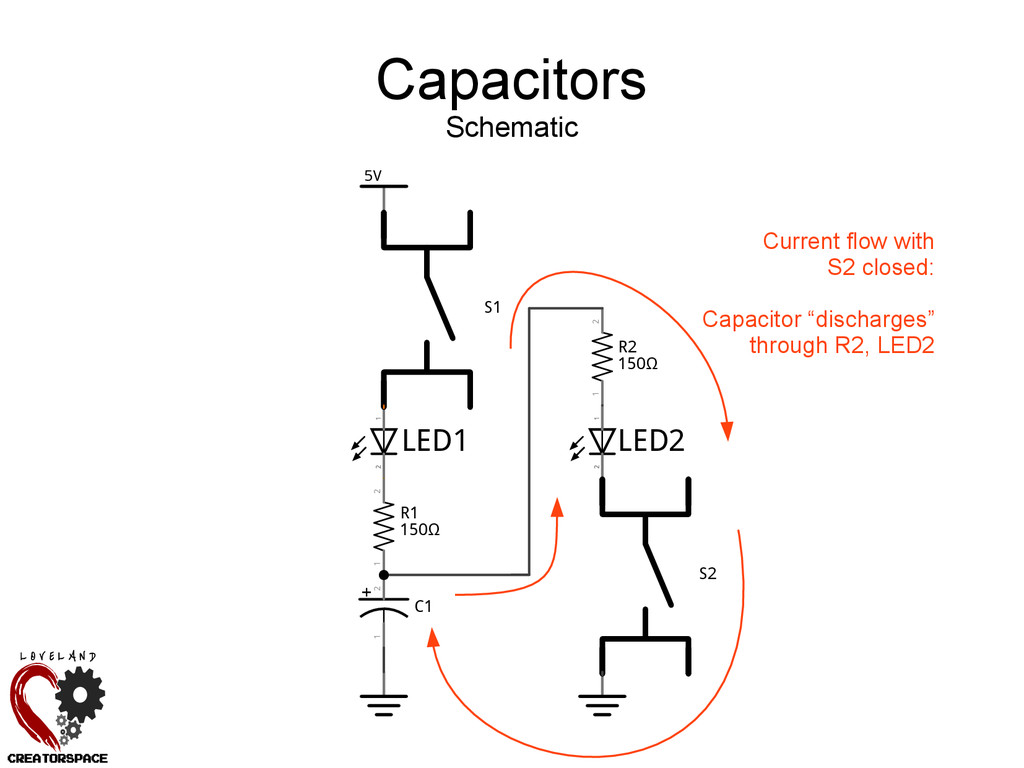
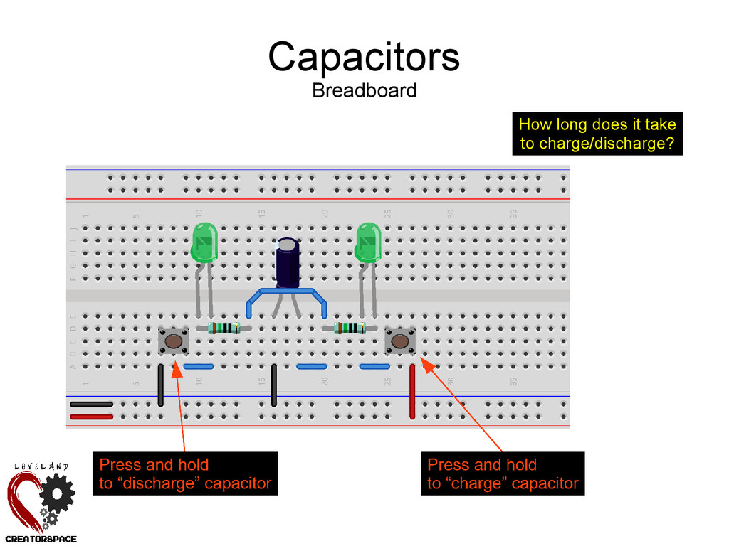
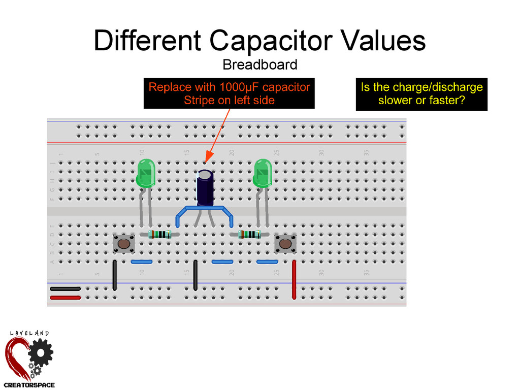
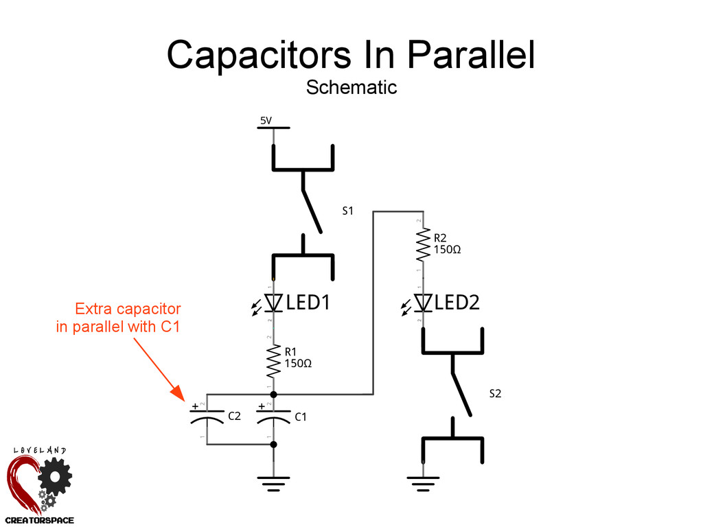
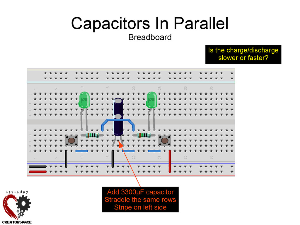
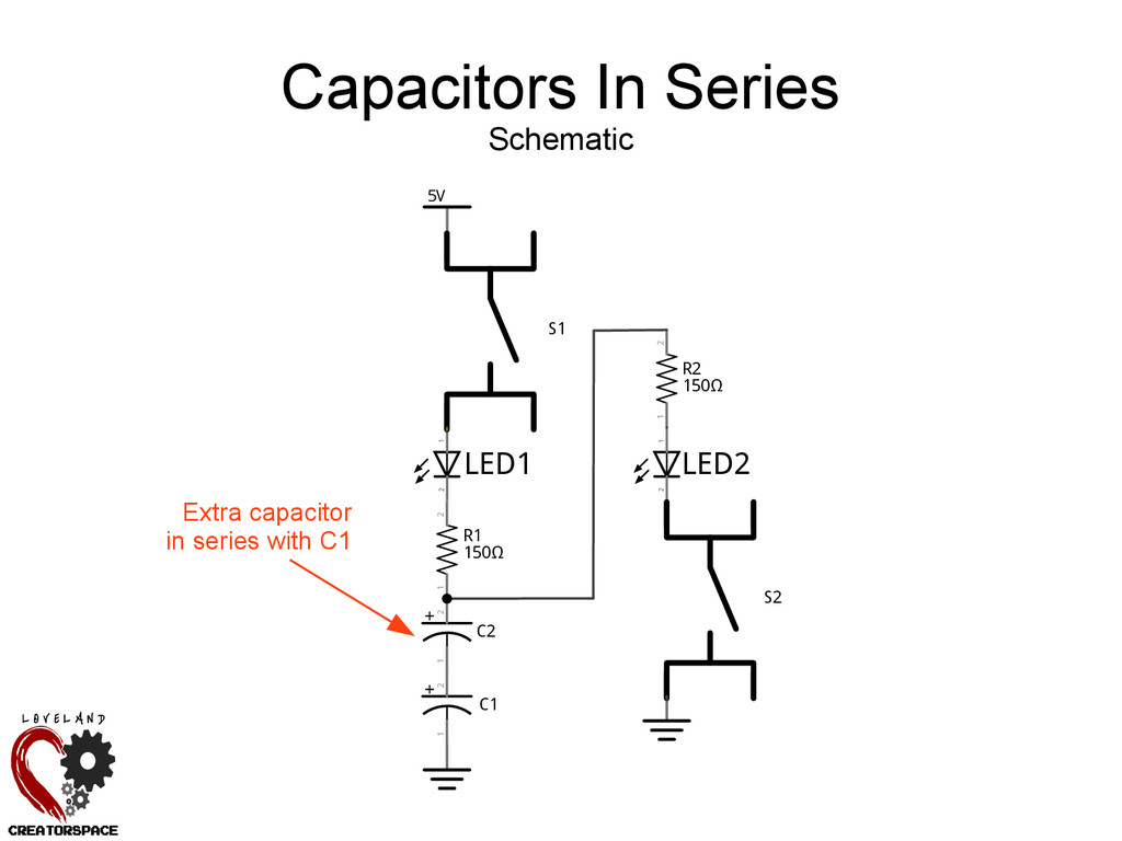
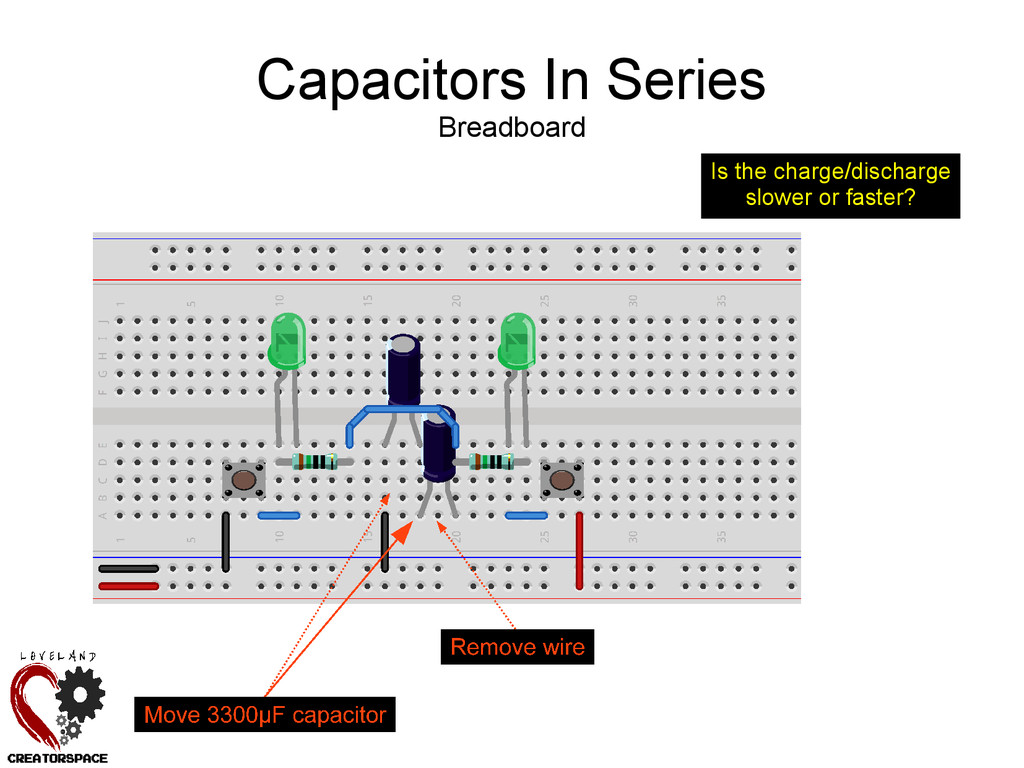
• Can release (or acquire) energy much more quickly, and at a higher current, than batteries • Some are polarized, some aren't • Value measured in Farads (F), but Farads are huge – Typical values ~10pF through perhaps 10,000μF • If connected to a power source, will “charge up” • If power removed, will discharge, and can power a circuit • Time take to charge/discharge related to value useful in timing circuits + +
unported http://creativecommons.org/licenses/by-sa/3.0/deed.en • http://en.wikipedia.org/wiki/File:Wall-Wart-AC-Adapter.jpg Public domain • http://en.wikipedia.org/wiki/File:A_plug.jpg CC BY SA 3.0 unported http://creativecommons.org/licenses/by-sa/3.0/deed.en • http://en.wikipedia.org/wiki/File:Electrical_outlet_with_label.jpg CC BY SA 3.0 unported http://creativecommons.org/licenses/by-sa/3.0/deed.en • http://en.wikipedia.org/wiki/File:A_few_Jumper_Wires.jpg CC BY SA 2.0 generic http://creativecommons.org/licenses/by-sa/2.0/deed.en • http://commons.wikimedia.org/wiki/File:Cable_Cross_Section.svg CC BY SA 3.0 http://creativecommons.org/licenses/by-sa/3.0/deed.en • http://en.wikipedia.org/wiki/File:400_points_breadboard.jpg CC BY SA 2.0 generic http://creativecommons.org/licenses/by-sa/2.0/deed.en
http://en.wikipedia.org/wiki/File:Resistor.jpg • http://en.wikipedia.org/wiki/File:Danotherm_HS50_power_resistor.jpg Public domain • http://en.wikipedia.org/wiki/File:Sil_resistor.png Public domain • http://bit.ly/my-templates https://drive.google.com/previewtemplate?id=1lWeBgAR_CIHPSBInJ29pKoF0bN0YCUG2NX6V9EKPN4o&mode=public CC BY SA 3.0 http://creativecommons.org/licenses/by-sa/3.0/ • http://en.wikipedia.org/wiki/File:Verschiedene_LEDs.jpg CC BY SA 2.0 generic http://creativecommons.org/licenses/by-sa/2.0/deed.en • http://en.wikipedia.org/wiki/File:Diodes.jpg CC BY SA 3.0 unported http://creativecommons.org/licenses/by-sa/3.0/deed.en
unported http://creativecommons.org/licenses/by-sa/3.0/deed.en • http://en.wikipedia.org/wiki/File:Electrolytic_capacitor.jpg CC BY 3.0 http://creativecommons.org/licenses/by/3.0/ • http://en.wikipedia.org/wiki/File:Tactile_switches.jpg CC BY SA 3.0 unported http://creativecommons.org/licenses/by-sa/3.0/deed.en • http://www.flickr.com/photos/g4ll4is/7125837749/sizes/n/ CC BY SA 2.0 http://creativecommons.org/licenses/by-sa/2.0/ • http://www.flickr.com/photos/arionfoto/4186043024/sizes/m/ CC BY ND 2.0 http://creativecommons.org/licenses/by-nd/2.0/