Upgrade to Pro — share decks privately, control downloads, hide ads and more …

Building Oscillating Circuits (multivibrators) Using Transistors

Building Oscillating Circuits (multivibrators) Using Transistors

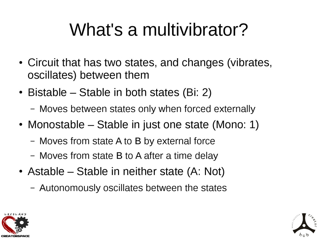
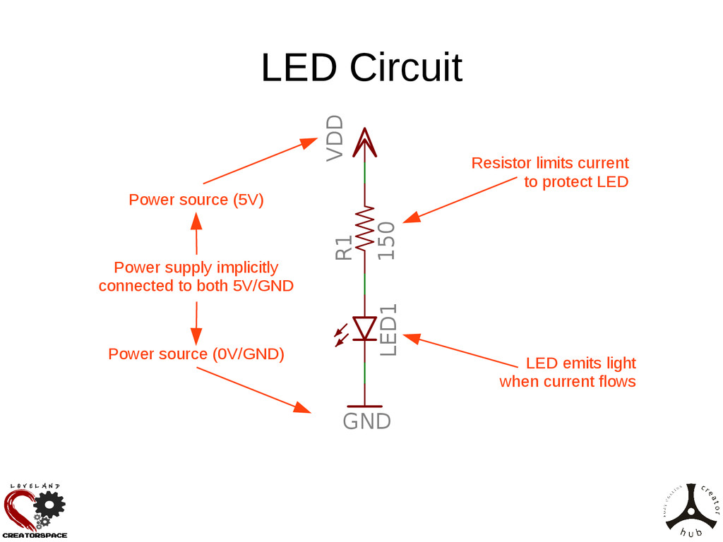
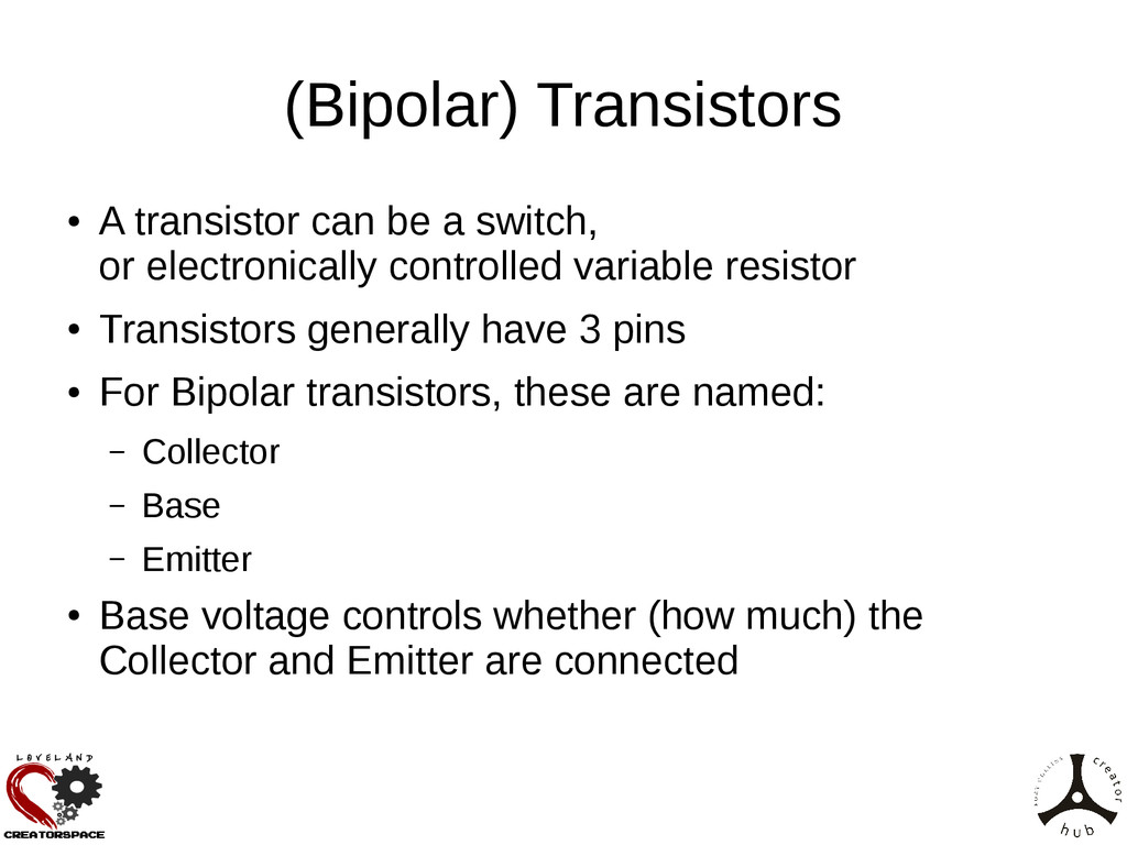
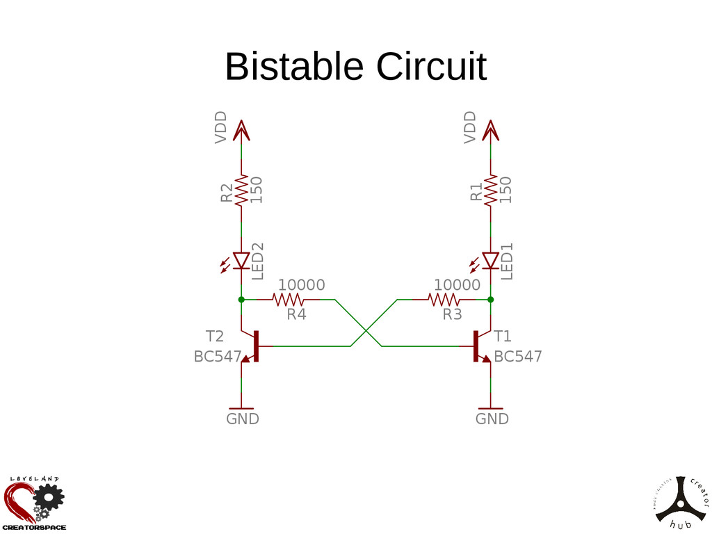
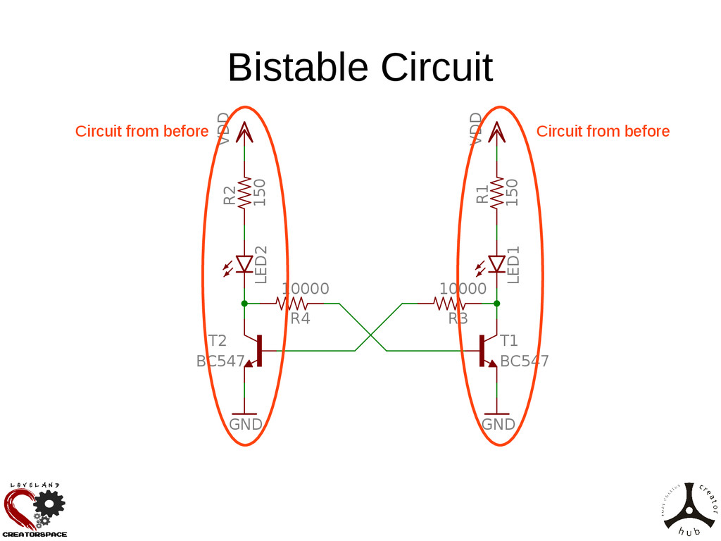
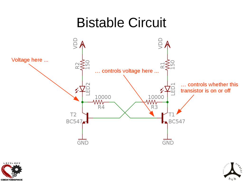
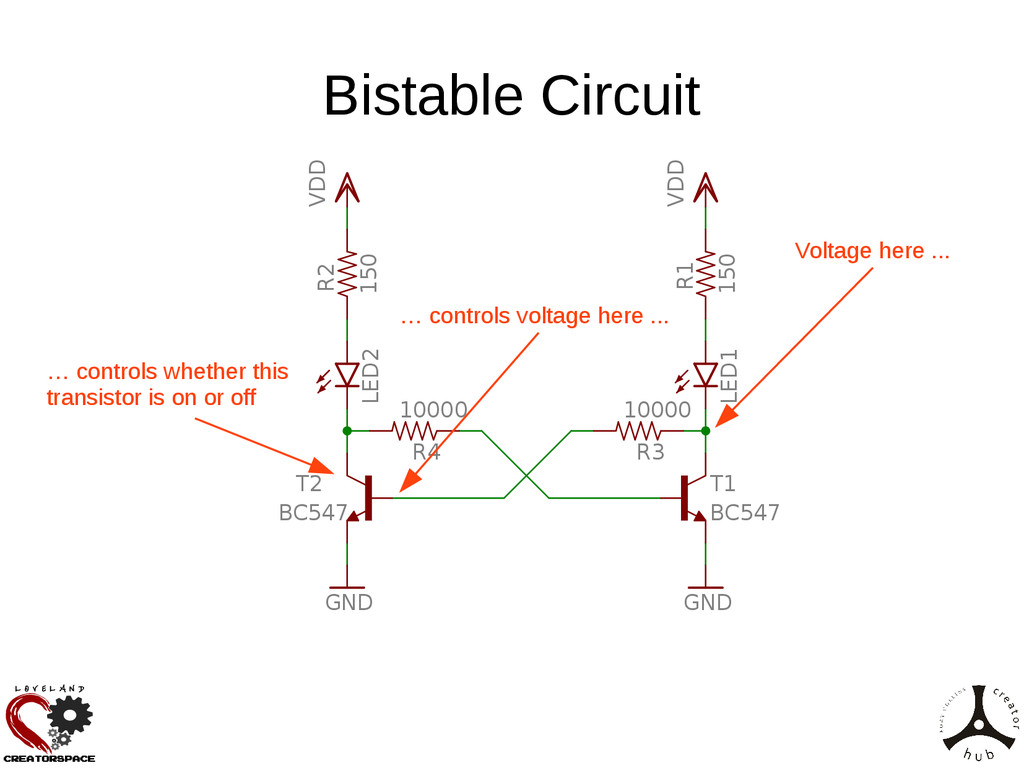
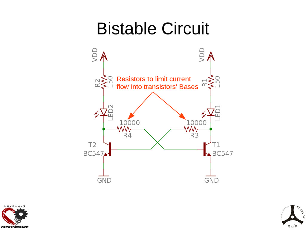
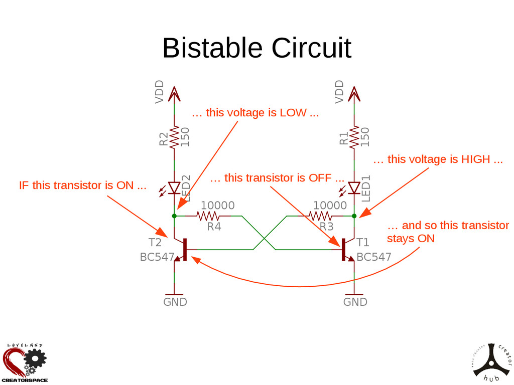
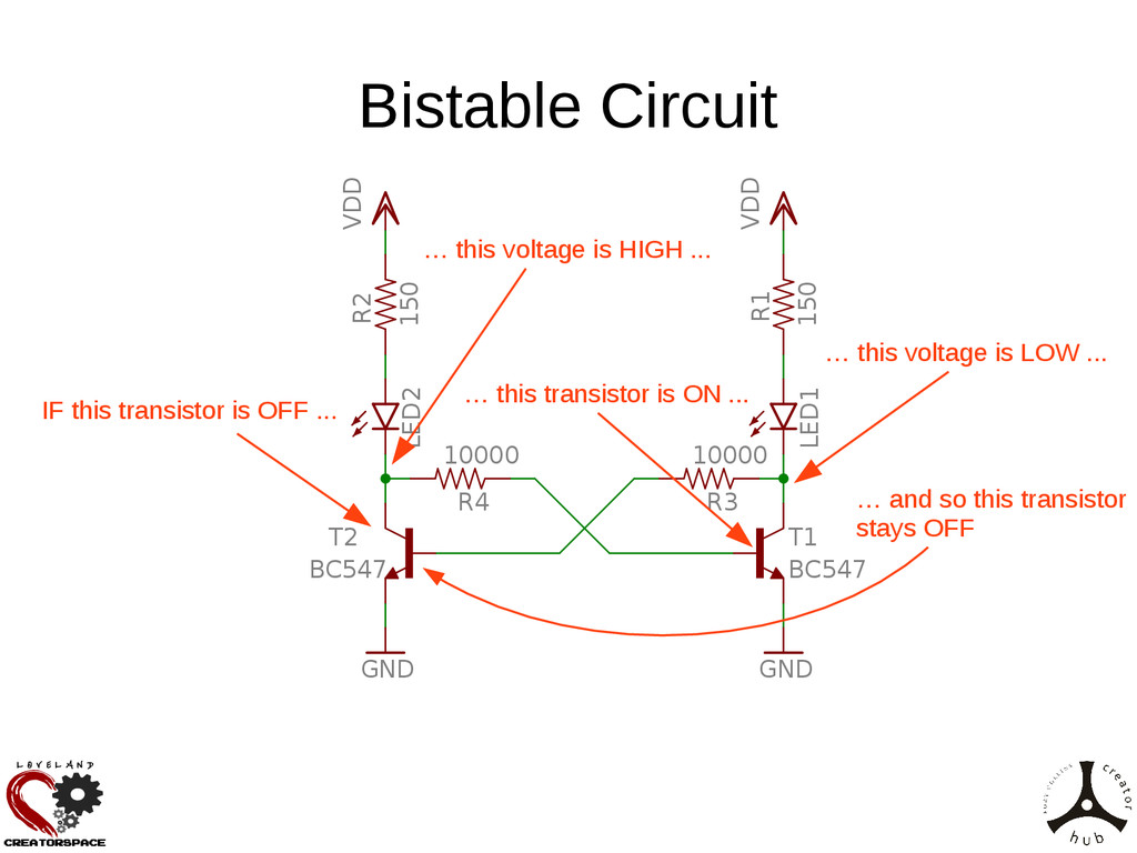
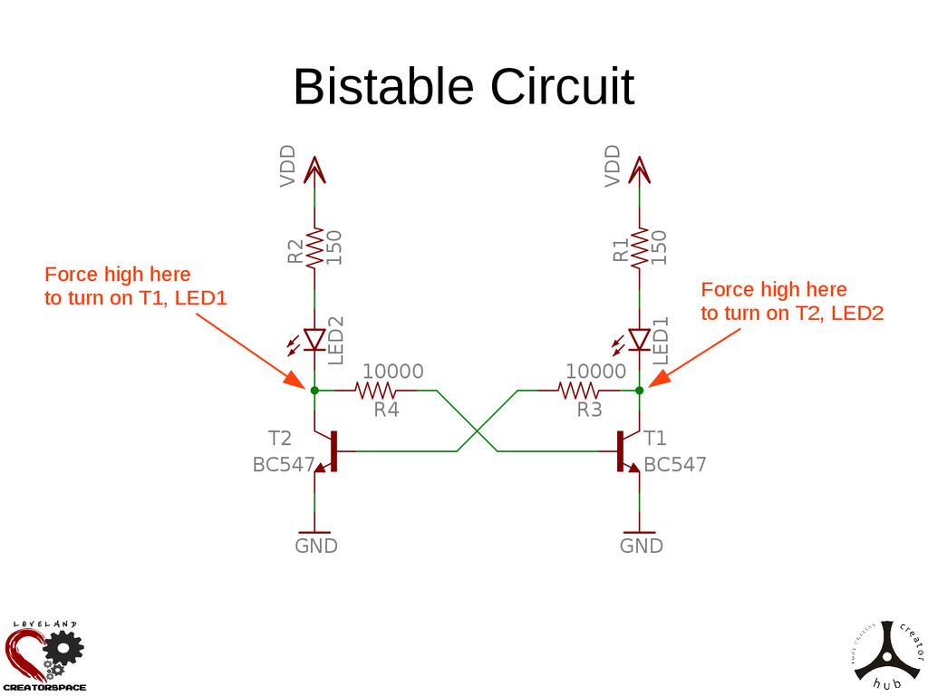
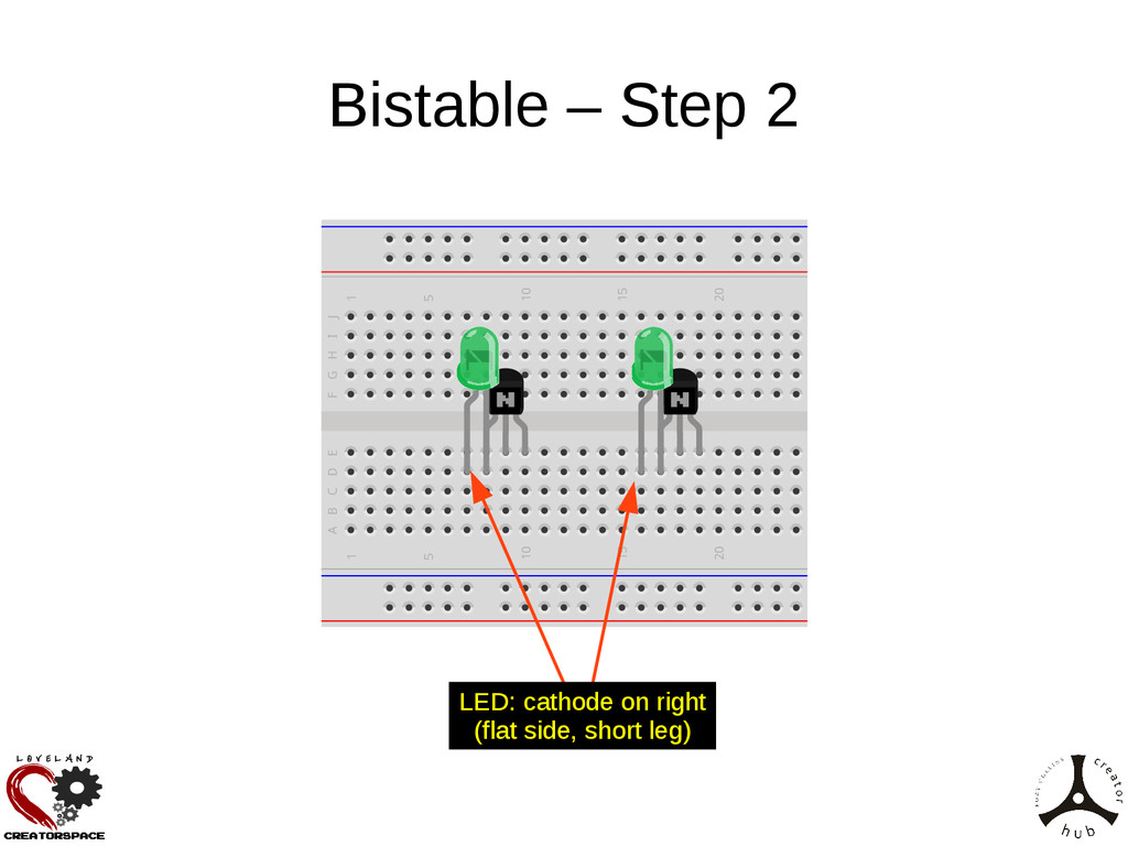
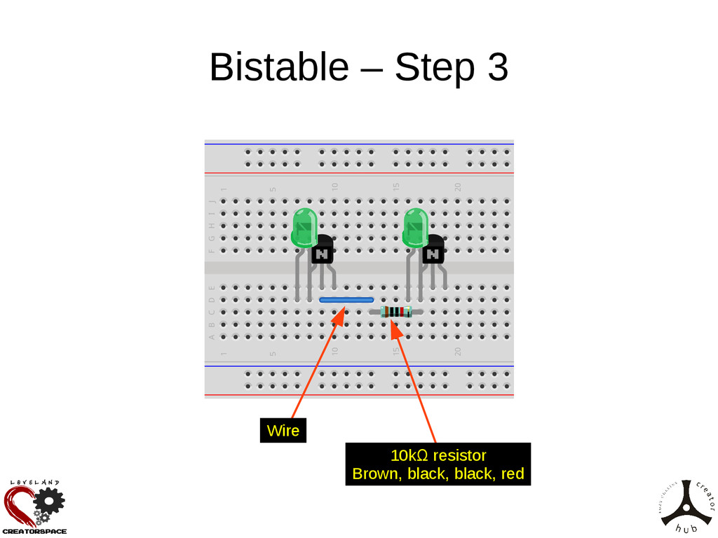
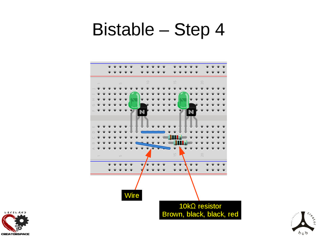
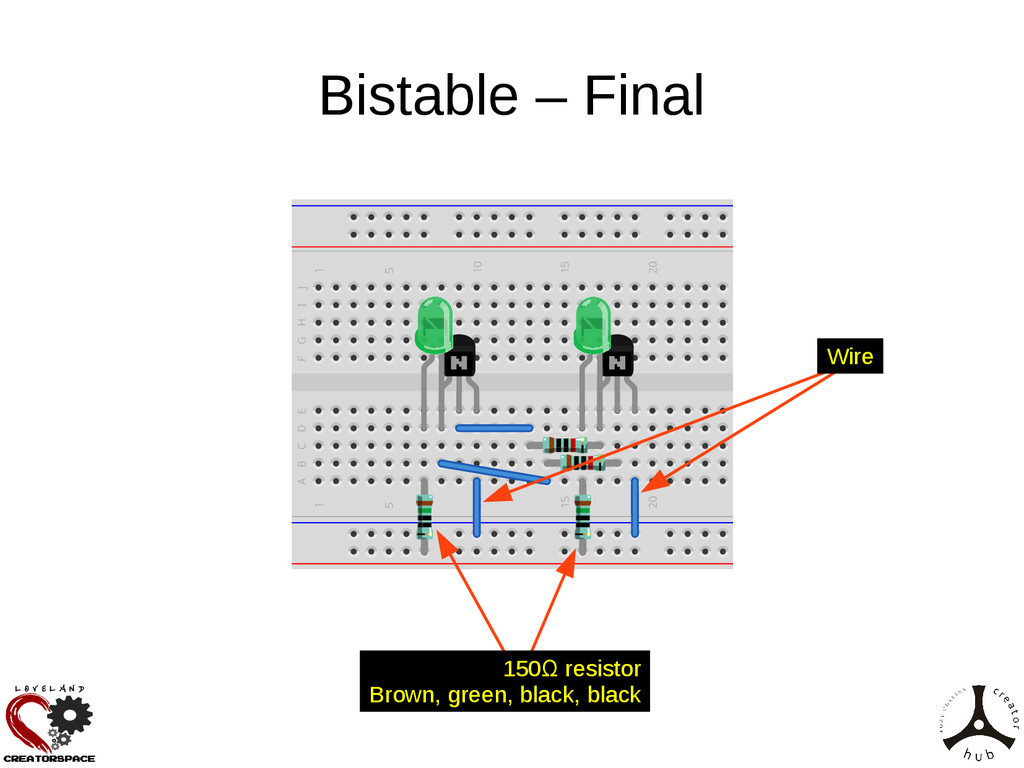
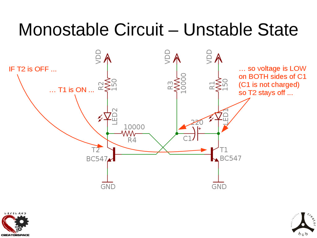
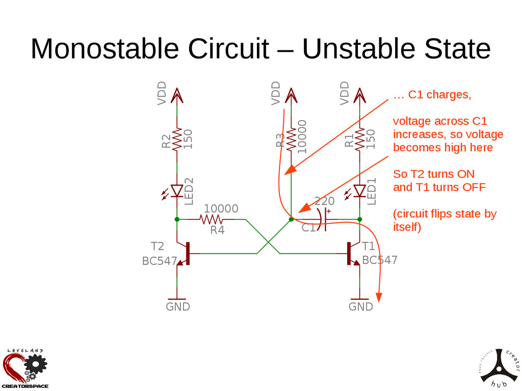
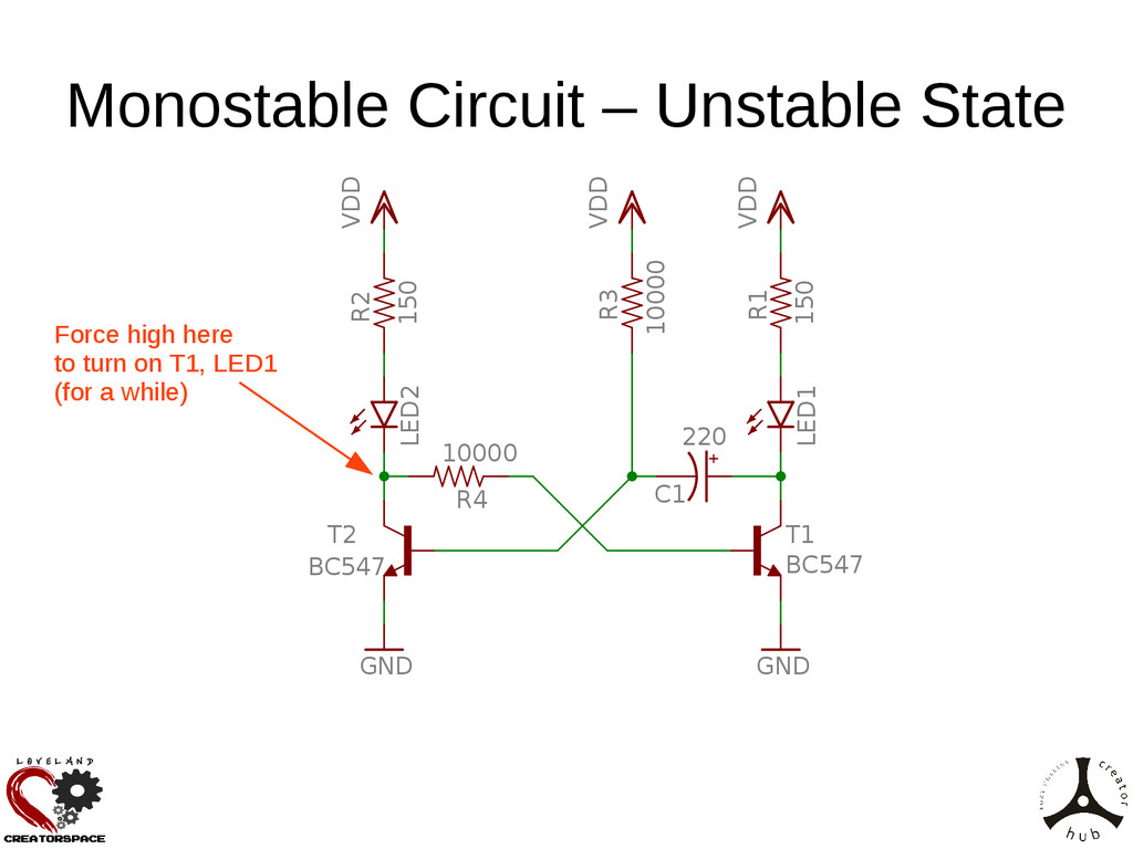
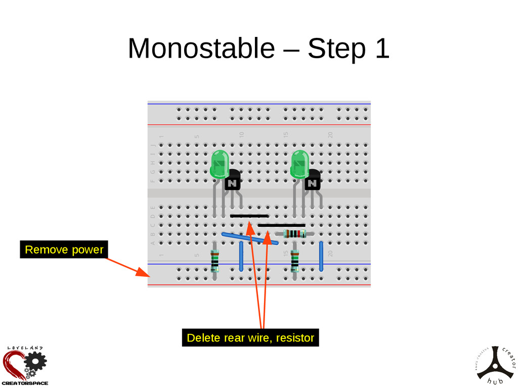
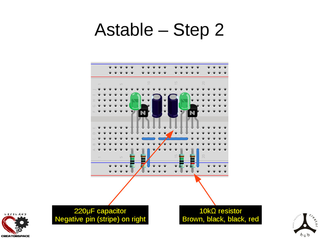
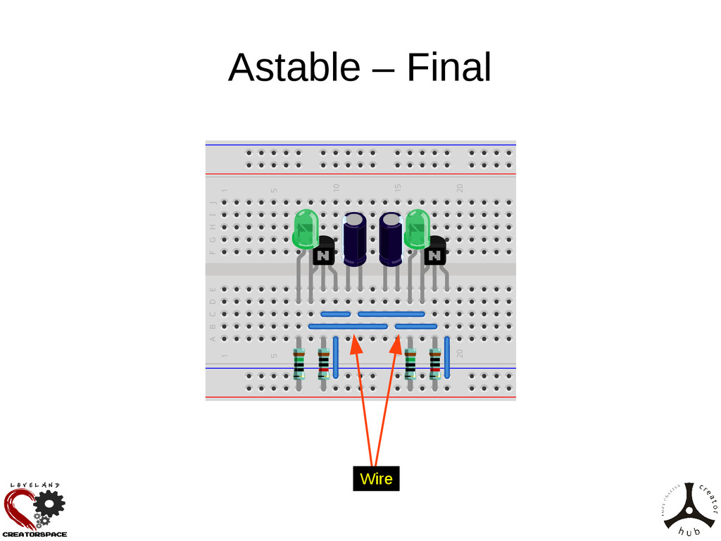
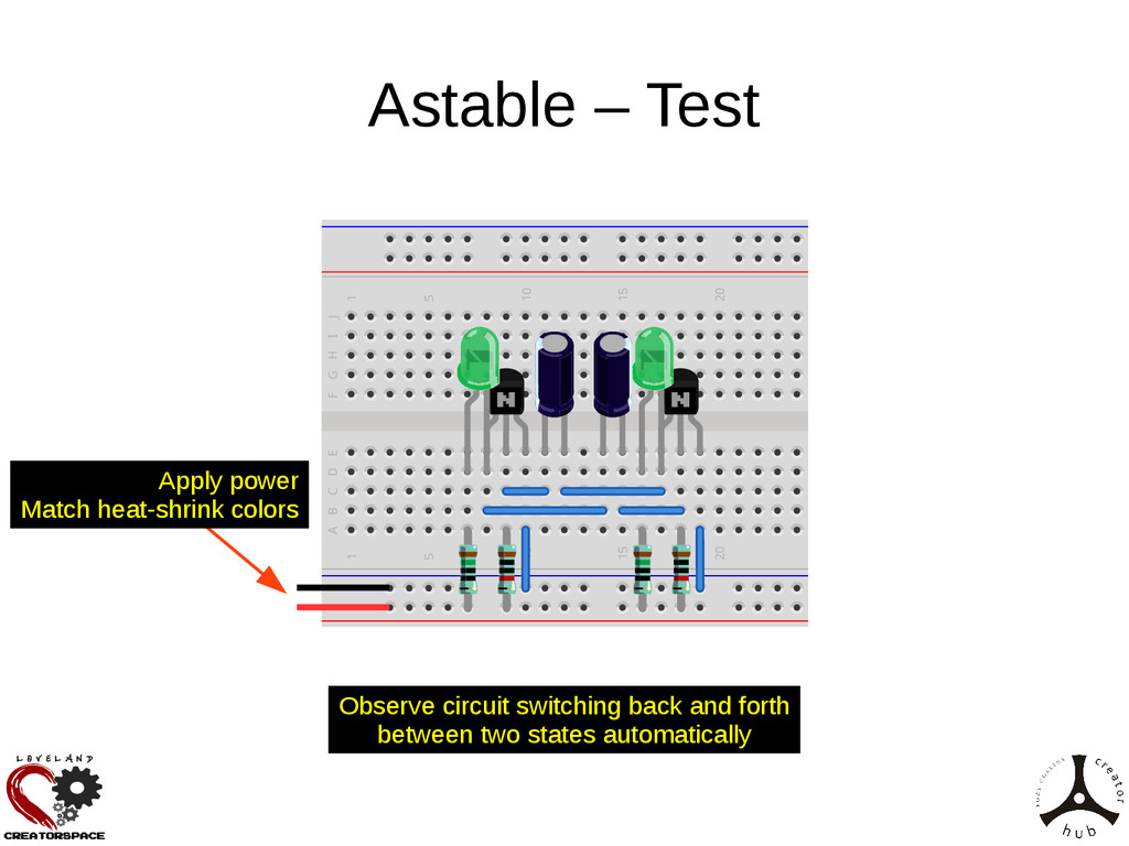
Let's learn about oscillating circuits (multivibrators). We'll cover some theory of operation of transistors, and how they can be used in circuits that (a) keep a device either on or off on request (bistable), (b) turn a device on for a short time, then off again (monostable), or (c) continually flash on and off (astable). We'll build each of these circuits on a breadboard, and use them to control LEDs.

Stephen Warren

January 11, 2015
Tweet

More Decks by Stephen Warren

Other Decks in Technology

Transcript

  1. Introduction • What is a multivibrator? • Different types (bistable,

    monostable, astable) • Walk through of the circuits • Build the circuits
  2. What's a multivibrator? • Circuit that has two states, and

    changes (vibrates, oscillates) between them • Bistable – Stable in both states (Bi: 2) – Moves between states only when forced externally • Monostable – Stable in just one state (Mono: 1) – Moves from state A to B by external force – Moves from state B to A after a time delay • Astable – Stable in neither state (A: Not) – Autonomously oscillates between the states
  3. LED Circuit GND LED1 R1 150 VDD Power source (5V)

    Power source (0V/GND) Power supply implicitly connected to both 5V/GND LED emits light when current flows Resistor limits current to protect LED
  4. (Bipolar) Transistors • A transistor can be a switch, or

    electronically controlled variable resistor • Transistors generally have 3 pins • For Bipolar transistors, these are named: – Collector – Base – Emitter • Base voltage controls whether (how much) the Collector and Emitter are connected
  5. Transistor – Pictures and Symbols C E B B C

    E PNP (Pointing iN Proudly) NPN (Not Pointing iN)
  6. Transistors - Operation • Base-Emitter current determines Collector-Emitter current •

    Transistors often characterized as amplifying current: The more Base current flows, the more Collector-Emitter current can flow. • A Base voltage is required to cause a Base current to flow • NPN: Turns on when Base is high (cf. Emitter) • PNP: Turns on when Base is low (cf. Emitter)
  7. Transistor Circuit GND LED1 R1 150 T1 BC547 VDD If

    transistor is ON, LED connected to GND so lights up If transistor is OFF, LED not connected to GND, so does not light If Base is HIGH, transistor is ON If Base is LOW, transistor is OFF
  8. Bistable Circuit GND GND LED1 LED2 R1 150 R2 150

    R3 10000 R4 10000 T1 BC547 T2 BC547 VDD VDD
  9. Bistable Circuit GND GND LED1 LED2 R1 150 R2 150

    R3 10000 R4 10000 T1 BC547 T2 BC547 VDD VDD Circuit from before Circuit from before
  10. Bistable Circuit GND GND LED1 LED2 R1 150 R2 150

    R3 10000 R4 10000 T1 BC547 T2 BC547 VDD VDD Voltage here ... … controls voltage here ... … controls whether this transistor is on or off
  11. Bistable Circuit GND GND LED1 LED2 R1 150 R2 150

    R3 10000 R4 10000 T1 BC547 T2 BC547 VDD VDD Voltage here ... … controls voltage here ... … controls whether this transistor is on or off
  12. Bistable Circuit GND GND LED1 LED2 R1 150 R2 150

    R3 10000 R4 10000 T1 BC547 T2 BC547 VDD VDD Resistors to limit current flow into transistors' Bases
  13. Bistable Circuit GND GND LED1 LED2 R1 150 R2 150

    R3 10000 R4 10000 T1 BC547 T2 BC547 VDD VDD IF this transistor is ON ... … this voltage is LOW ... … this transistor is OFF ... … this voltage is HIGH ... … and so this transistor stays ON
  14. Bistable Circuit GND GND LED1 LED2 R1 150 R2 150

    R3 10000 R4 10000 T1 BC547 T2 BC547 VDD VDD IF this transistor is OFF ... … this voltage is HIGH ... … this transistor is ON ... … this voltage is LOW ... … and so this transistor stays OFF
  15. Bistable Circuit GND GND LED1 LED2 R1 150 R2 150

    R3 10000 R4 10000 T1 BC547 T2 BC547 VDD VDD Force high here to turn on T1, LED1 Force high here to turn on T2, LED2
  16. • Used for quick circuit prototyping • Holes to plug

    components' wires into • Internal wires connect some of the holes Breadboards Power rails along edges Main body is columns of 5 connected holes Columns are numbered Rows are named Gutter for ICs Two sides of gutter not connected
  17. Placing components • Polarity – Some components don't work backwards

    • Don't bend pins – Slight angling OK, no need for kinks • Don't burn out LEDs – By connecting to power with no resistor • Don't connect power until circuit is complete
  18. Transistor Packages TO-92 package Kit contains: BC547 (use this; has

    pink dot on back) BS170 (we won't use this) E-line package Kit contains: ZVP2110A (we won't use this)
  19. Bistable – Step 1 1 1 5 5 10 10

    15 15 20 20 25 25 30 30 35 35 40 40 A B C D E F G H I J BC547 (pink dot) Flat side towards you 6 hole gap horizontally Red line nearest you At least 3 hole gap horizontally to edge
  20. Bistable – Step 2 1 1 5 5 10 10

    15 15 20 20 25 25 30 30 35 35 40 40 A B C D E F G H I J LED: cathode on right (flat side, short leg)
  21. Bistable – Step 3 1 1 5 5 10 10

    15 15 20 20 25 25 30 30 35 35 40 40 A B C D E F G H I J Wire 10kΩ resistor Brown, black, black, red
  22. Bistable – Step 4 1 1 5 5 10 10

    15 15 20 20 25 25 30 30 35 35 40 40 A B C D E F G H I J Wire 10kΩ resistor Brown, black, black, red
  23. Bistable – Final 1 1 5 5 10 10 15

    15 20 20 25 25 30 30 35 35 40 40 A B C D E F G H I J Wire 150Ω resistor Brown, green, black, black
  24. Bistable – Test 1 1 5 5 10 10 15

    15 20 20 25 25 30 30 35 35 40 40 A B C D E F G H I J Touch wire from POWER … to either LED's right pin One pin at a time Apply power Match heat-shrink colors
  25. Monostable Circuit C1 220 GND GND LED1 LED2 R1 150

    R2 150 R3 10000 R4 10000 T1 BC547 T2 BC547 VDD VDD VDD
  26. Monostable Circuit C1 220 GND GND LED1 LED2 R1 150

    R2 150 R3 10000 R4 10000 T1 BC547 T2 BC547 VDD VDD VDD Different
  27. Monostable Circuit – Stable State C1 220 GND GND LED1

    LED2 R1 150 R2 150 R3 10000 R4 10000 T1 BC547 T2 BC547 VDD VDD VDD IF T2 is ON ... … T1 is OFF ... … so ignore this!
  28. Monostable Circuit – Unstable State C1 220 GND GND LED1

    LED2 R1 150 R2 150 R3 10000 R4 10000 T1 BC547 T2 BC547 VDD VDD VDD IF T2 is OFF ... … T1 is ON ... … so voltage is LOW on BOTH sides of C1 (C1 is not charged) so T2 stays off ...
  29. Monostable Circuit – Unstable State C1 220 GND GND LED1

    LED2 R1 150 R2 150 R3 10000 R4 10000 T1 BC547 T2 BC547 VDD VDD VDD … C1 charges, voltage across C1 increases, so voltage becomes high here So T2 turns ON and T1 turns OFF (circuit flips state by itself)
  30. Monostable Circuit – Unstable State C1 220 GND GND LED1

    LED2 R1 150 R2 150 R3 10000 R4 10000 T1 BC547 T2 BC547 VDD VDD VDD Force high here to turn on T1, LED1 (for a while)
  31. Monostable – Step 1 1 1 5 5 10 10

    15 15 20 20 25 25 30 30 35 35 40 40 A B C D E F G H I J Delete rear wire, resistor Remove power
  32. Monostable – Step 2 1 1 5 5 10 10

    15 15 20 20 25 25 30 30 35 35 40 40 A B C D E F G H I J 10kΩ resistor Brown, black, black, red 220μF capacitor Negative pin (stripe) on left
  33. Monostable – Final 1 1 5 5 10 10 15

    15 20 20 25 25 30 30 35 35 40 40 A B C D E F G H I J Wire
  34. Monostable – Test 1 1 5 5 10 10 15

    15 20 20 25 25 30 30 35 35 40 40 A B C D E F G H I J Touch wire from POWER … to left LED's right pin Wait for LEDs to change automatically Apply power Match heat-shrink colors
  35. Astable Circuit C1 220 C2 220 GND GND LED1 LED2

    R1 150 R2 150 R3 10000 R4 10000 T1 BC547 T2 BC547 VDD VDD VDD VDD
  36. Astable Circuit C1 220 C2 220 GND GND LED1 LED2

    R1 150 R2 150 R3 10000 R4 10000 T1 BC547 T2 BC547 VDD VDD VDD VDD Different
  37. Astable Circuit – Unstable state 1 C1 220 C2 220

    GND GND LED1 LED2 R1 150 R2 150 R3 10000 R4 10000 T1 BC547 T2 BC547 VDD VDD VDD VDD IF T2 is ON ... … T1 is OFF ... C2 charges ... and eventually T1 turns ON, T2 turns OFF
  38. Astable Circuit – Unstable state 2 C1 220 C2 220

    GND GND LED1 LED2 R1 150 R2 150 R3 10000 R4 10000 T1 BC547 T2 BC547 VDD VDD VDD VDD IF T2 is OFF ... … T1 is ON ... C1 charges ... and eventually T2 turns ON, T1 turns OFF
  39. Astable – Step 1 1 1 5 5 10 10

    15 15 20 20 25 25 30 30 35 35 40 40 A B C D E F G H I J Delete front wire, resistor Remove power
  40. Astable – Step 2 1 1 5 5 10 10

    15 15 20 20 25 25 30 30 35 35 40 40 A B C D E F G H I J 220μF capacitor Negative pin (stripe) on right 10kΩ resistor Brown, black, black, red
  41. Astable – Final 1 1 5 5 10 10 15

    15 20 20 25 25 30 30 35 35 40 40 A B C D E F G H I J Wire
  42. Astable – Test 1 1 5 5 10 10 15

    15 20 20 25 25 30 30 35 35 40 40 A B C D E F G H I J Apply power Match heat-shrink colors Observe circuit switching back and forth between two states automatically