to move to another town because of her job • We need three layers • It is hierarchical (the tasks must be done in the order given in the hierarchy) • Each layer uses the services of the layer immediately below it • Each layer gives the services to the layer immediately above it
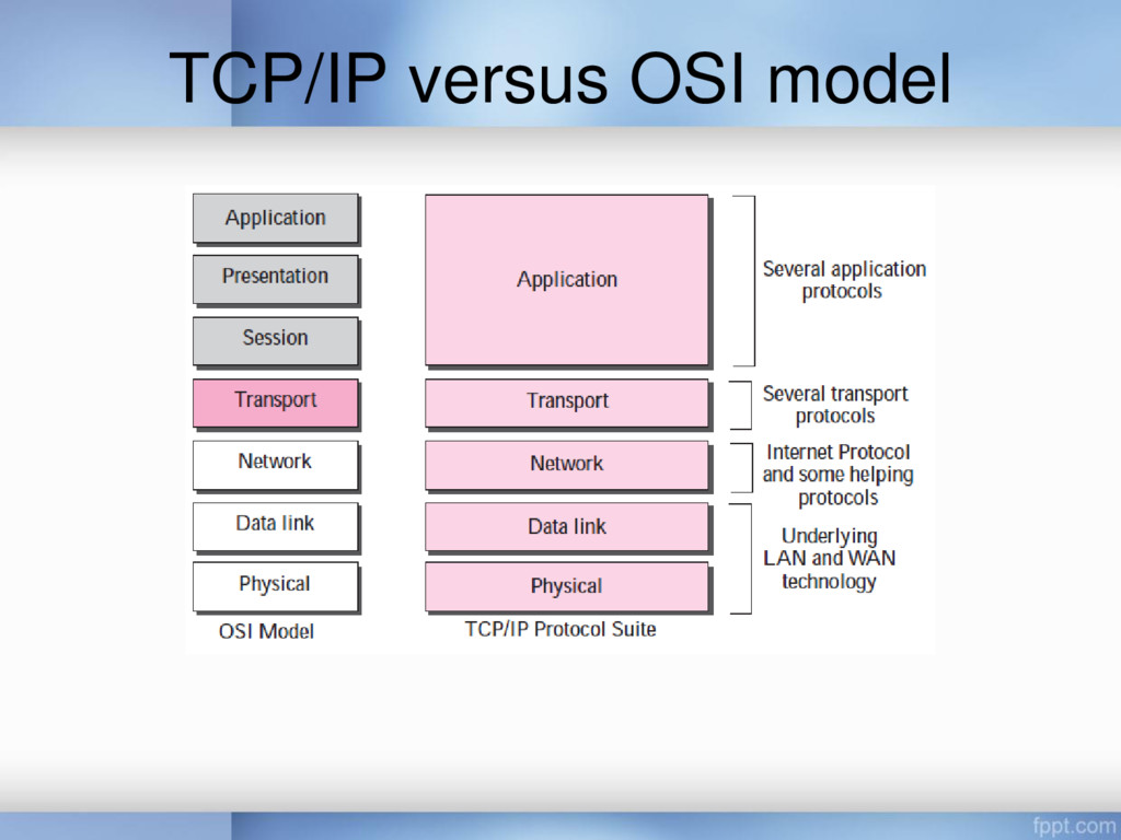
a multinational body dedicated to worldwide agreement on international standards • An ISO standard that covers all aspects of network communications is the Open Systems Interconnection (OSI) model – It was first introduced in the late 1970s
allows any two different systems to communicate regardless of their underlying architecture • The OSI model is not a protocol; it is a model for understanding and designing a network architecture that is flexible, robust, and interoperable • The OSI model was intended to be the basis for the creation of the protocols in the OSI stack
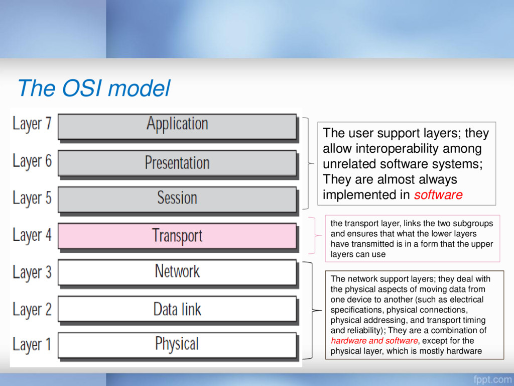
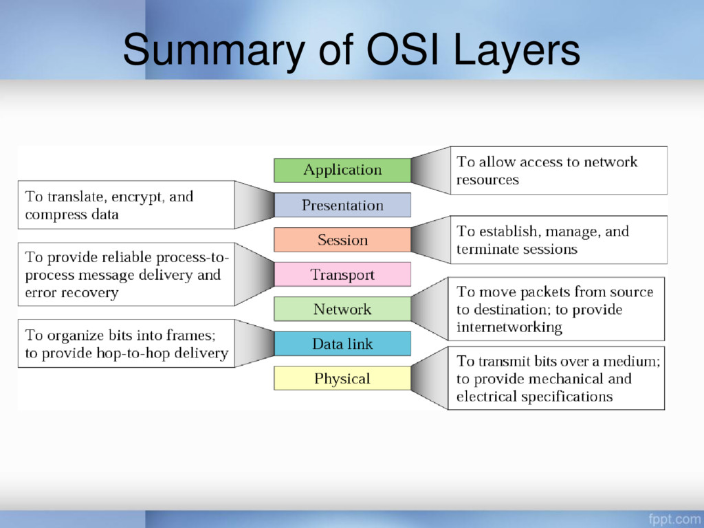
the physical aspects of moving data from one device to another (such as electrical specifications, physical connections, physical addressing, and transport timing and reliability); They are a combination of hardware and software, except for the physical layer, which is mostly hardware The user support layers; they allow interoperability among unrelated software systems; They are almost always implemented in software the transport layer, links the two subgroups and ensures that what the lower layers have transmitted is in a form that the upper layers can use
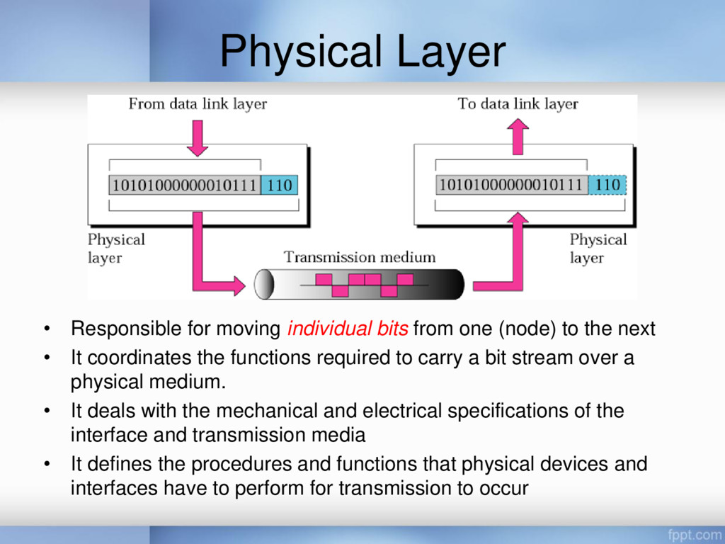
(node) to the next • It coordinates the functions required to carry a bit stream over a physical medium. • It deals with the mechanical and electrical specifications of the interface and transmission media • It defines the procedures and functions that physical devices and interfaces have to perform for transmission to occur
Physical characteristics of interfaces and media • Representation of bits • Data rate • Synchronization of bits • Line configuration • Physical topology • Transmission mode
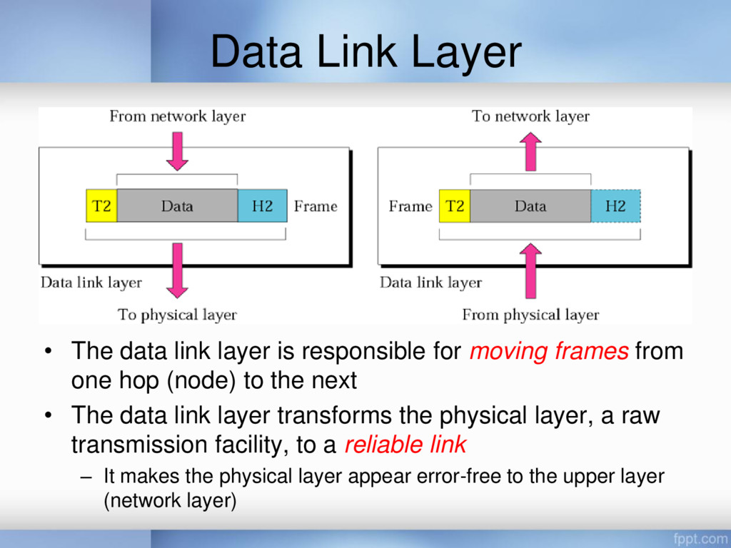
for moving frames from one hop (node) to the next • The data link layer transforms the physical layer, a raw transmission facility, to a reliable link – It makes the physical layer appear error-free to the upper layer (network layer)
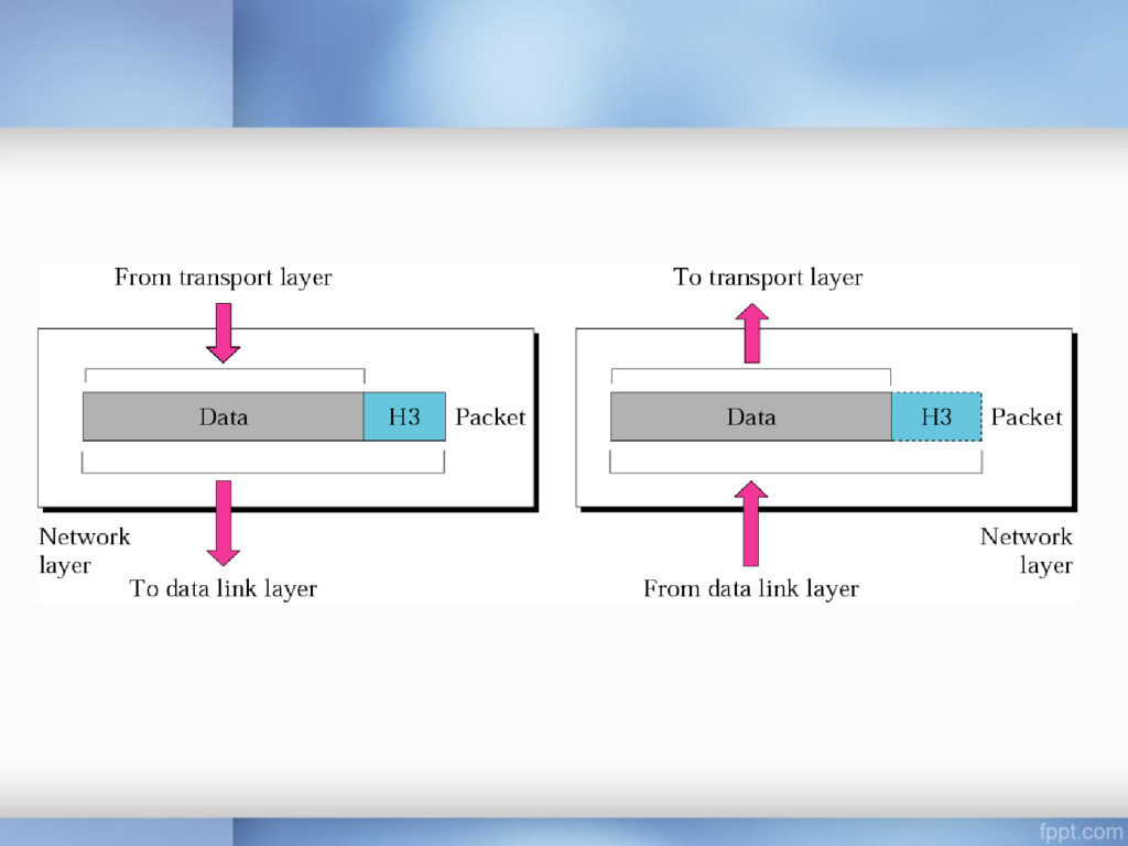
source-to-destination delivery of a packet, possibly across multiple networks (links) • Whereas the data link layer oversees the delivery of the packet between two systems on the same network (link) • The network layer ensures that each packet gets from its point of origin to its final destination
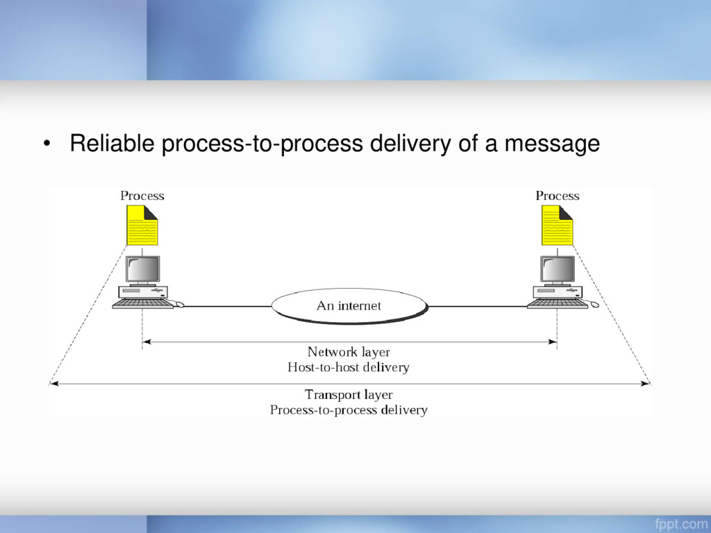
delivery of individual packets – It does not recognize any relationship between those packets • The transport layer ensures that the whole message arrives intact and in order – Overseeing both error control and flow control at the source- to-destination level
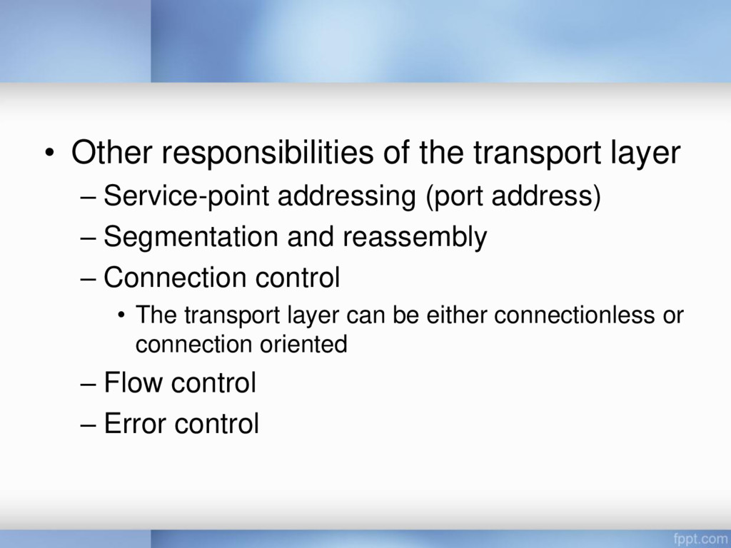
(port address) – Segmentation and reassembly – Connection control • The transport layer can be either connectionless or connection oriented – Flow control – Error control
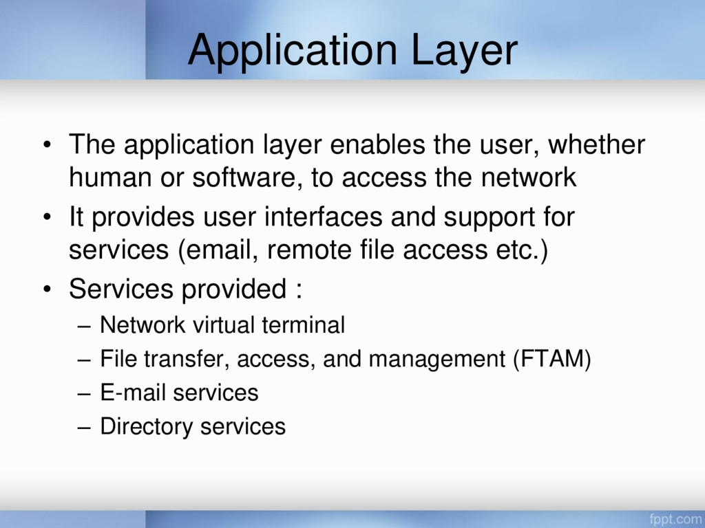
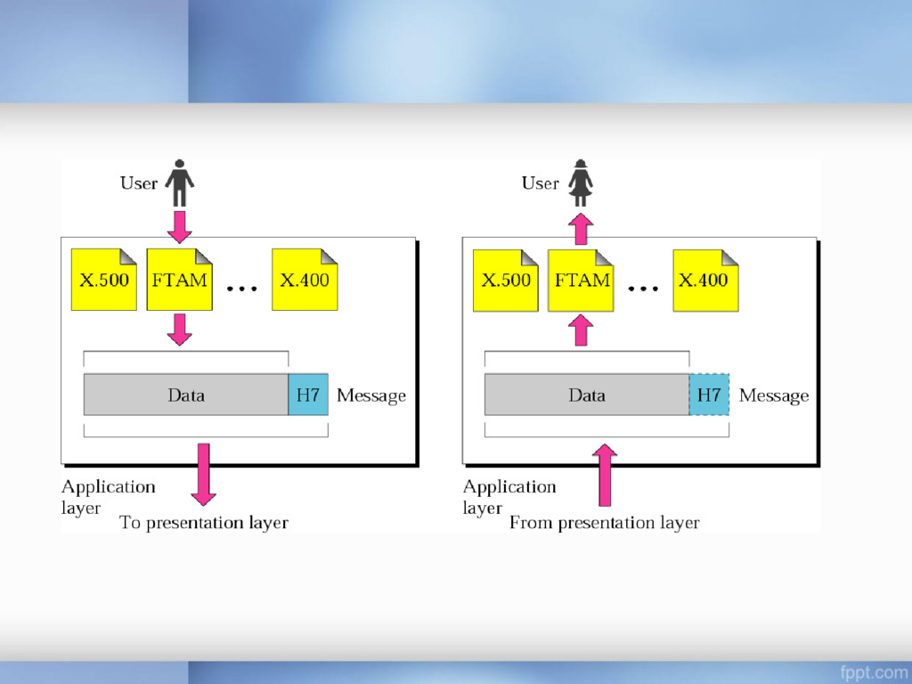
human or software, to access the network • It provides user interfaces and support for services (email, remote file access etc.) • Services provided : – Network virtual terminal – File transfer, access, and management (FTAM) – E-mail services – Directory services
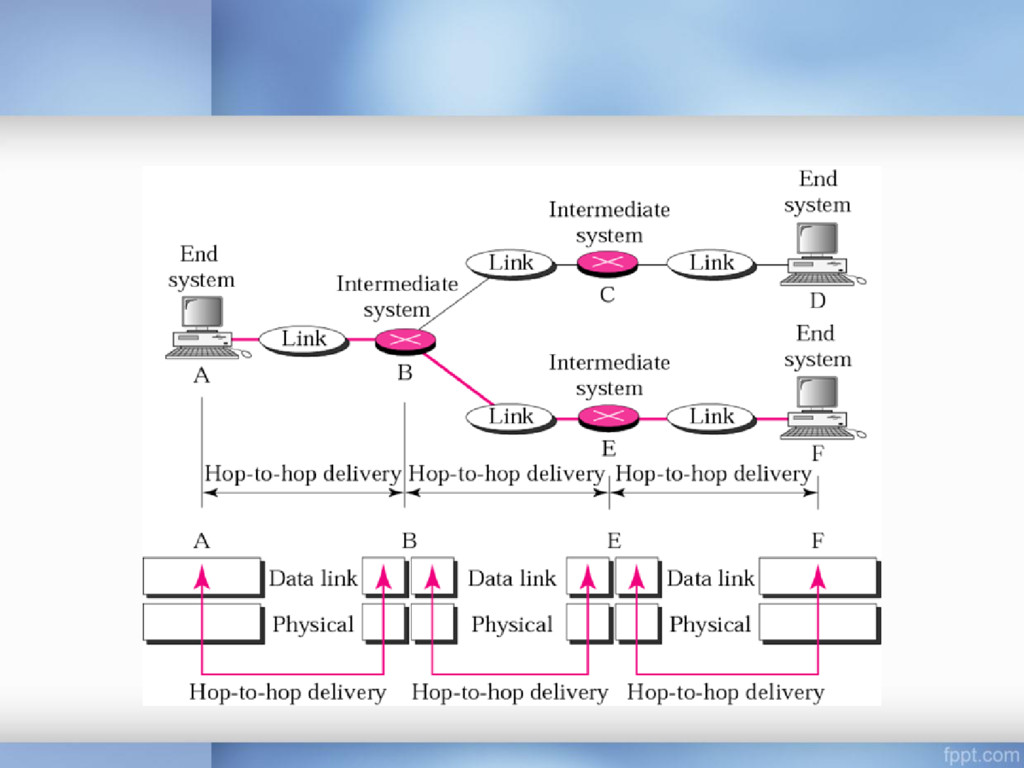
for the physical layer • It supports all of the standard and proprietary protocols • The communication is between two hops or nodes, either a computer or router • The unit of communication is a single bit
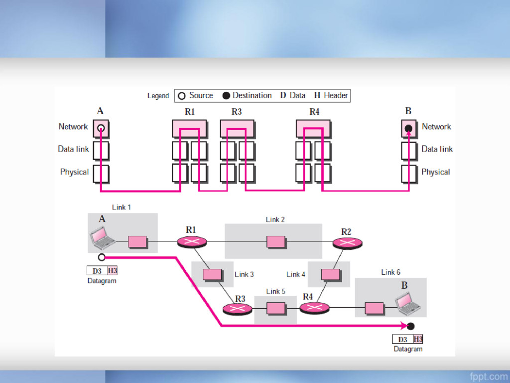
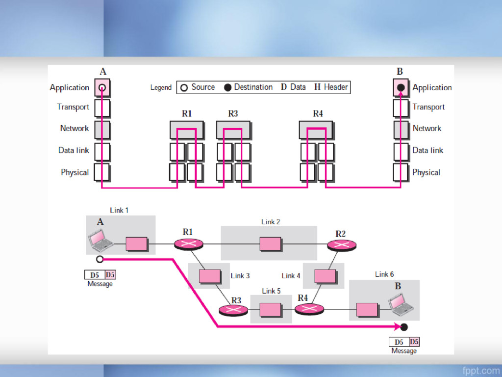
each other is via routers R1, R3, and R4 if a node is connected to n links, it needs n physical-layer protocols, one for each link because links may use different physical-layer protocols
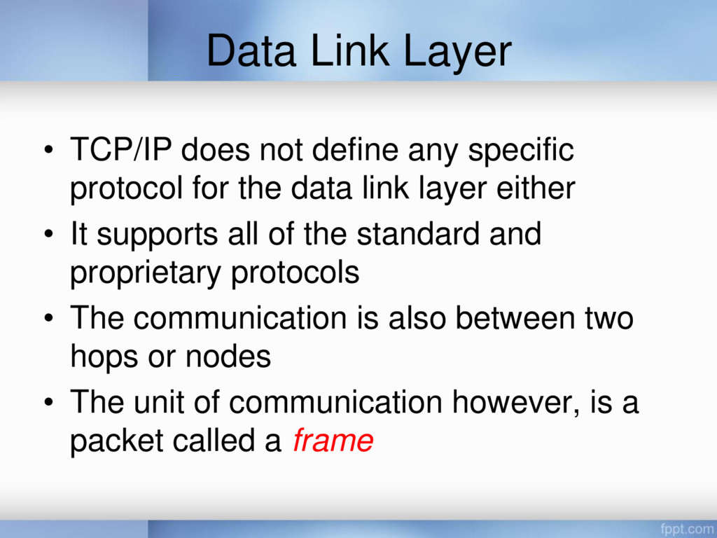
protocol for the data link layer either • It supports all of the standard and proprietary protocols • The communication is also between two hops or nodes • The unit of communication however, is a packet called a frame
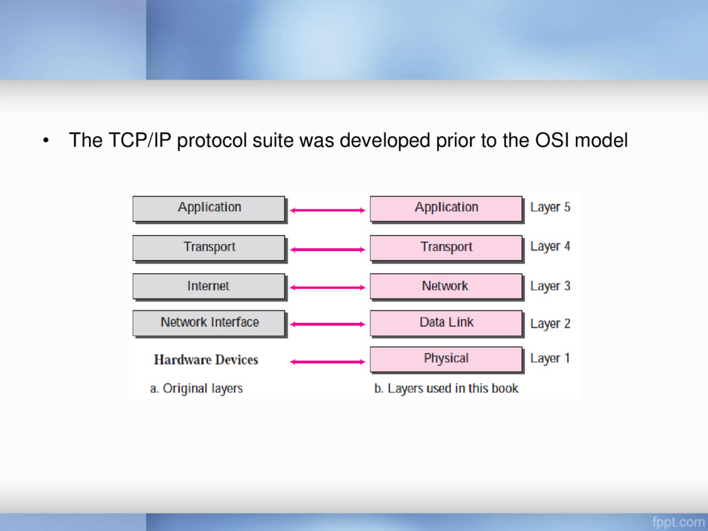
the internetwork layer), TCP/IP supports the Internet Protocol (IP) • IP is the transmission mechanism used by the TCP/IP protocols • IP transports data in packets called datagrams, each of which is transported separately • Datagrams can travel along different routes and can arrive out of sequence or be duplicated • IP does not keep track of the routes and has no facility for reordering datagrams once they arrive at their destination
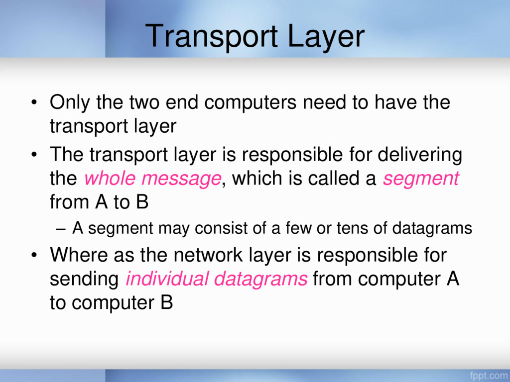
have the transport layer • The transport layer is responsible for delivering the whole message, which is called a segment from A to B – A segment may consist of a few or tens of datagrams • Where as the network layer is responsible for sending individual datagrams from computer A to computer B
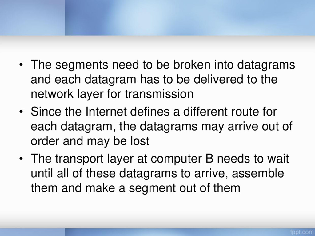
each datagram has to be delivered to the network layer for transmission • Since the Internet defines a different route for each datagram, the datagrams may arrive out of order and may be lost • The transport layer at computer B needs to wait until all of these datagrams to arrive, assemble them and make a segment out of them
by two protocols: – User Datagram Protocol (UDP) – Transmission Control Protocol (TCP) • A new protocol called Stream Control Transmission Protocol (SCTP) has been introduced in the last few years
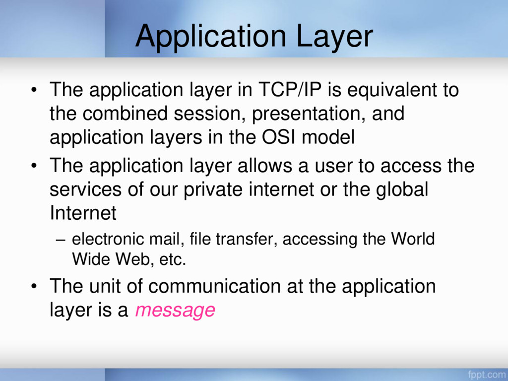
to the combined session, presentation, and application layers in the OSI model • The application layer allows a user to access the services of our private internet or the global Internet – electronic mail, file transfer, accessing the World Wide Web, etc. • The unit of communication at the application layer is a message
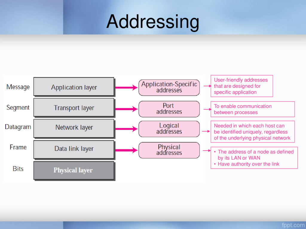
its LAN or WAN • Have authority over the link Needed in which each host can be identified uniquely, regardless of the underlying physical network To enable communication between processes User-friendly addresses that are designed for specific application
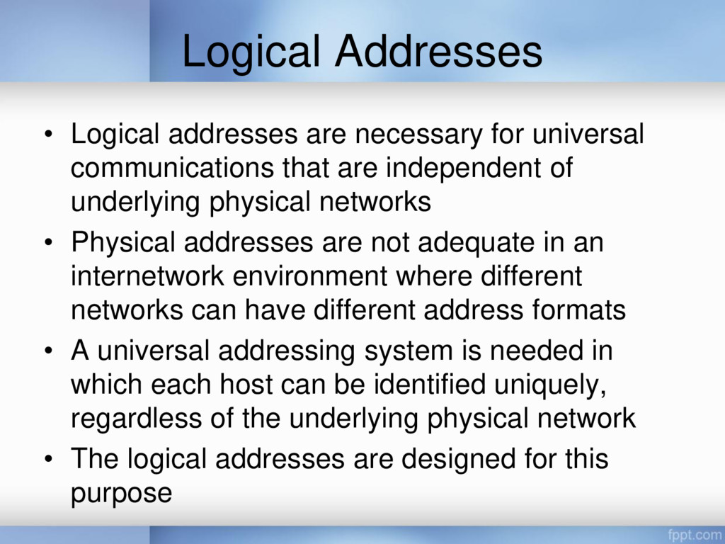
that are independent of underlying physical networks • Physical addresses are not adequate in an internetwork environment where different networks can have different address formats • A universal addressing system is needed in which each host can be identified uniquely, regardless of the underlying physical network • The logical addresses are designed for this purpose
32-bit address (IPv4) and a 128-bit address (IPv6), that can uniquely define a host connected to the Internet • No two publicly addressed and visible hosts on the Internet can have the same IP address
processes at the same time • The end objective of Internet communication is a process communicating with another process • For example, computer A can communicate with computer C by using TELNET, at the same time, computer A communicates with computer B by using the File Transfer Protocol (FTP) • In the TCP/IP architecture, the label assigned to a process is called a port address • A port address in TCP/IP is 16 bits in length (represented by one decimal number)
application • Examples include the e-mail address (for example, [email protected]) and the • Universal Resource Locator (URL) (for example, www.itb.ac.id)