Wires Coaxial Twisted Pair Twisted Pair Kabel serat optik Unguided transmission media infra merah gelombang radio microwave: terrestrial maupun satellite
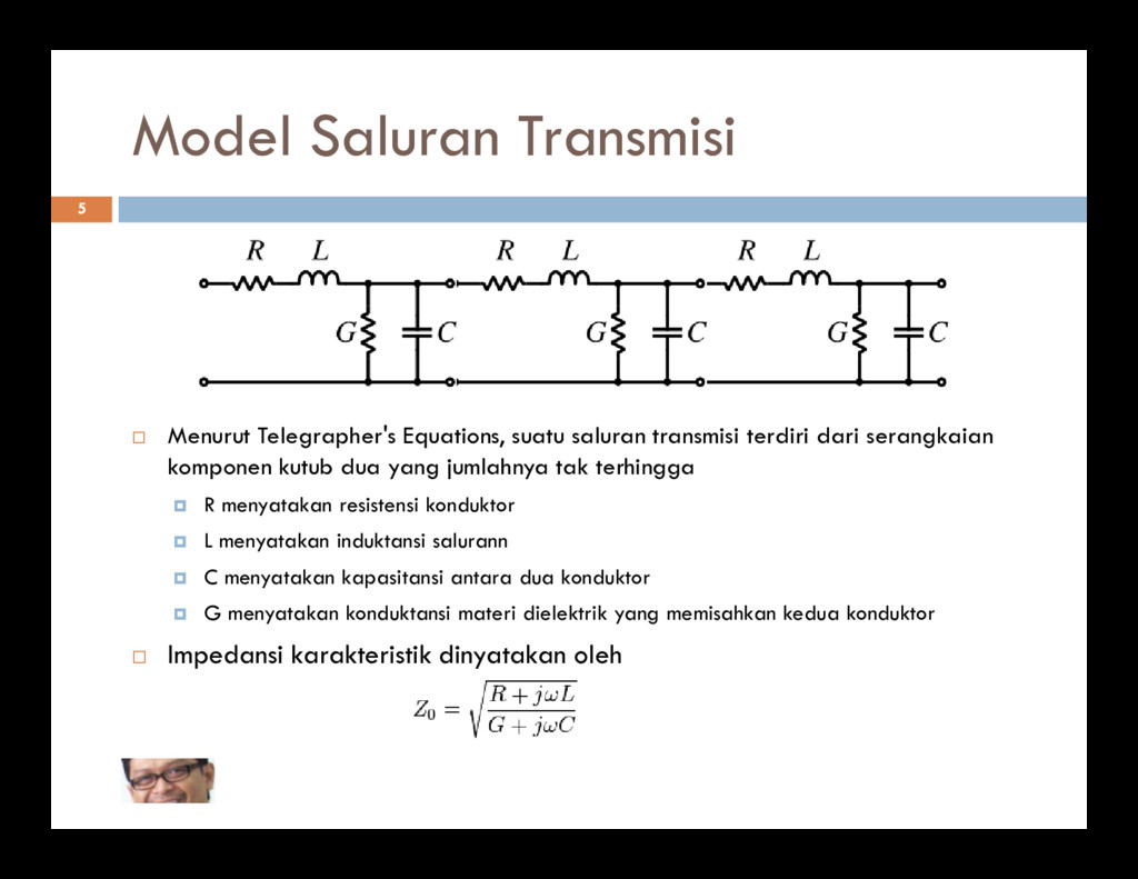
dari serangkaian 5 Menurut Telegrapher's Equations, suatu saluran transmisi terdiri dari serangkaian komponen kutub dua yang jumlahnya tak terhingga R menyatakan resistensi konduktor L menyatakan induktansi salurann C menyatakan kapasitansi antara dua konduktor G menyatakan konduktansi materi dielektrik yang memisahkan kedua konduktor Impedansi karakteristik dinyatakan oleh
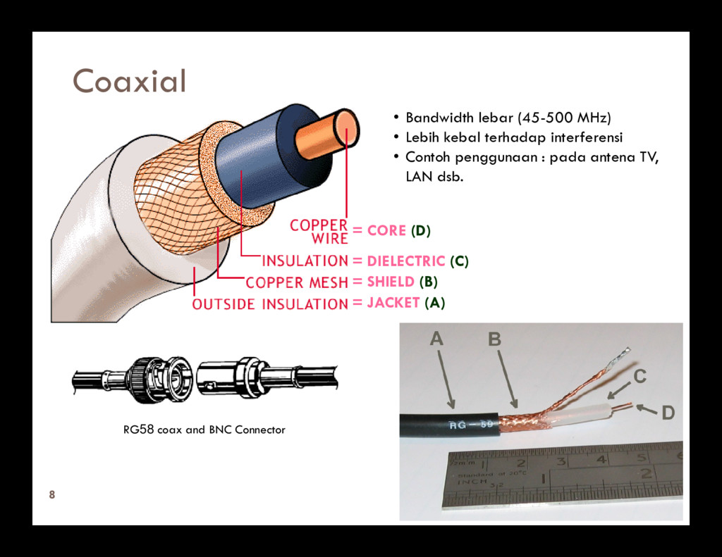
redaman tinggi dan sensitif terhadap interferensi Redaman pada suatu kabel tembaga akan meningkat bila frekuensi dinaikkan bila frekuensi dinaikkan Kecepatan rambat sinyal di dalam kabel tembaga mendekati 200.000 km/detik Tiga jenis kabel tembaga yang biasa digunakan: Open wire Coaxial Twisted Pair
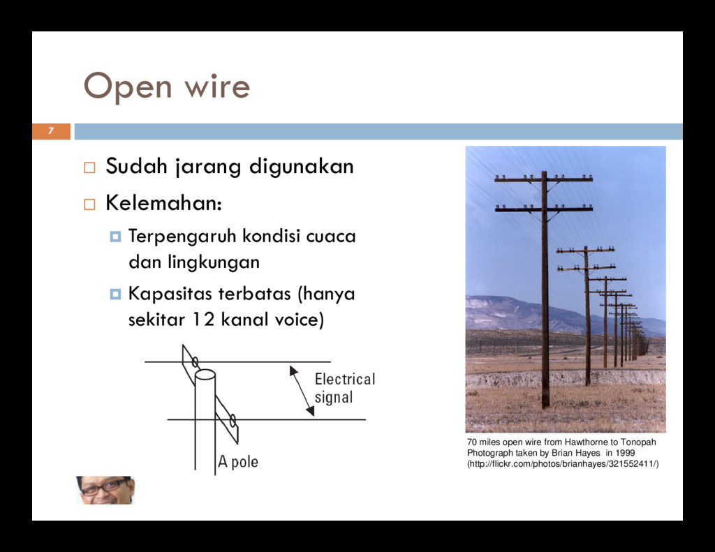
dan lingkungan Kapasitas terbatas (hanya sekitar 12 kanal voice) 70 miles open wire from Hawthorne to Tonopah Photograph taken by Brian Hayes in 1999 (http://flickr.com/photos/brianhayes/321552411/)
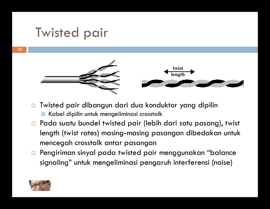
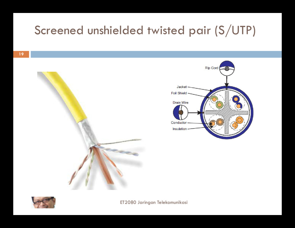
10 Twisted pair dibangun dari dua konduktor yang dipilin Kabel dipilin untuk mengeliminasi crosstalk Pada suatu bundel twisted pair (lebih dari satu pasang), twist length (twist rates) masing-masing pasangan dibedakan untuk mencegah crosstalk antar pasangan Pengiriman sinyal pada twisted pair menggunakan “balance signaling” untuk mengeliminasi pengaruh interferensi (noise)
are symmetric with respect to ground so that all current flows through the transmission line and the load 11 none through ground Note that line balance depends on the current through the line, not the voltage across the line It is also called differential signaling Source: York County Amateur Radio Society
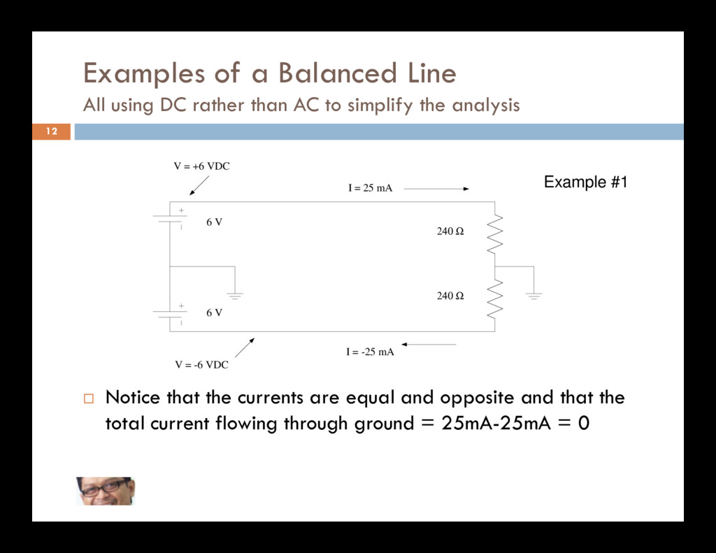
AC to simplify the analysis 12 I = 25 mA V = +6 VDC 6 V 240 Ω Example #1 Notice that the currents are equal and opposite and that the total current flowing through ground = 25mA-25mA = 0 6 V V = -6 VDC I = -25 mA 240 Ω
Ω Example #2 Note that the total current flowing through ground is again 0 Because the ground current is 0, the ground is not required V = -6 VDC I = -25 mA 240 Ω
types of antenna (dipoles, yagi etc.) are balanced load 15 So, to feed balanced antenna with unbalance transmission lines we have to use baluns (balance- unbalance)
smaller and lighter than electrical cables to do the same job Material Cost Fiber cable costs significantly less than copper cable for the same transmission capacity Information Capacity Recently, bit-rates of up to 14 Tbit/s have been reached over a single 160 km line using optical amplifiers No Electrical Connection Electrical connections have problems: Ground loops (in a conductor connecting two points that are supposed to be at the same potential, often ground, but are actually at different potentials) causing noises and interferences 24 actually at different potentials) causing noises and interferences Dangerous (must be protected) Lightning poses a severe hazard No Electromagnetic Interference Because the connection is not electrical, you can neither pick up nor create electrical interference (the major source of noise) Longer distances between Regenerators (hundreds of kilometers) Open Ended Capacity The maximum theoretical capacity of installed fiber is very great (almost infinite) Better Security It is possible to tap fiber optical cable. But it is very difficult to do and the additional loss caused by the tap is relatively easy to detect
silica glass and doped with germanium) Cladding Keeps light signal within core (Pure Silica Glass) Coating Protects Optical Fiber From Abrasion and External Pressures (UV Cured Acrylate)
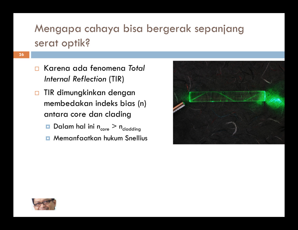
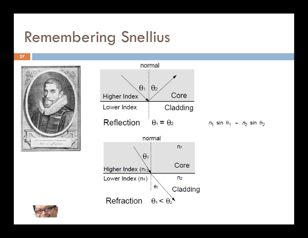
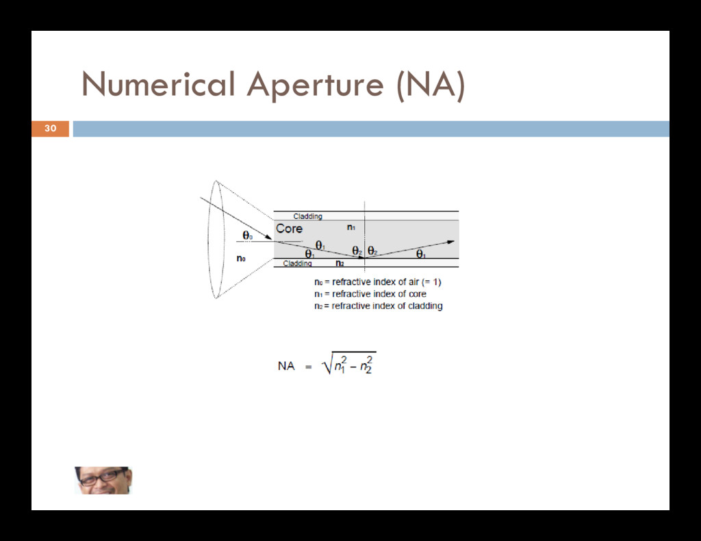
fenomena Total Internal Reflection (TIR) TIR dimungkinkan dengan membedakan indeks bias (n) antara core dan clading antara core dan clading Dalam hal ini ncore > ncladding Memanfaatkan hukum Snellius
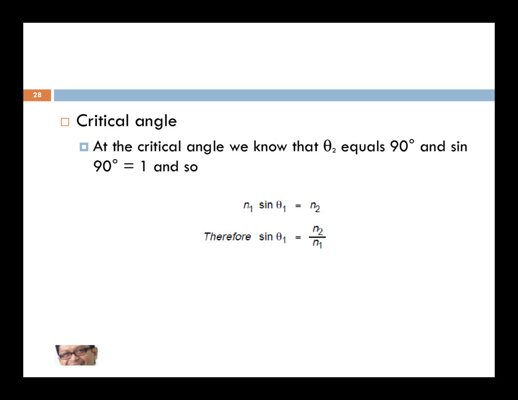
then the ray will propagate along the fiber and will be “bound” within the fiber (Total Internal Reflection) 29 where the angle θ1 is greater than the critical value the ray is refracted into the cladding and will ultimately be lost outside the fiber
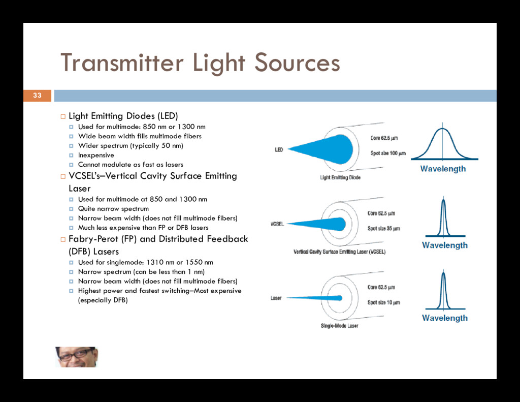
850 nm or 1300 nm Wide beam width fills multimode fibers Wider spectrum (typically 50 nm) Inexpensive Cannot modulate as fast as lasers VCSEL’s–Vertical Cavity Surface Emitting Laser Used for multimode at 850 and 1300 nm 33 Used for multimode at 850 and 1300 nm Quite narrow spectrum Narrow beam width (does not fill multimode fibers) Much less expensive than FP or DFB lasers Fabry-Perot (FP) and Distributed Feedback (DFB) Lasers Used for singlemode: 1310 nm or 1550 nm Narrow spectrum (can be less than 1 nm) Narrow beam width (does not fill multimode fibers) Highest power and fastest switching–Most expensive (especially DFB)
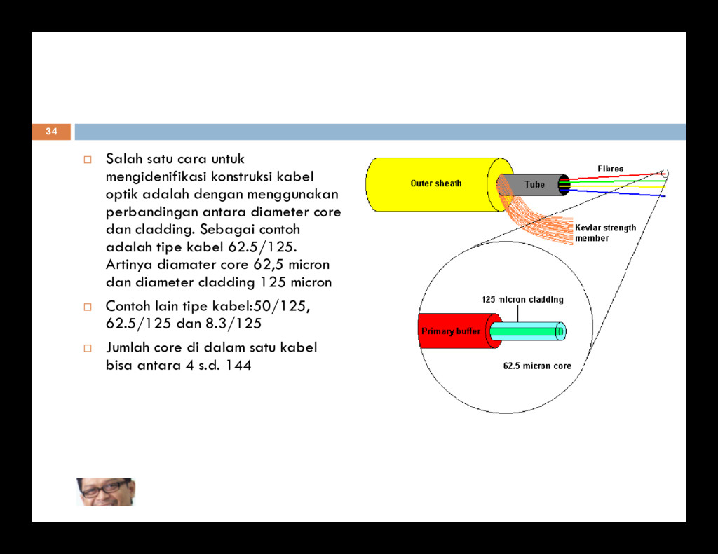
dengan menggunakan perbandingan antara diameter core dan cladding. Sebagai contoh adalah tipe kabel 62.5/125. Artinya diamater core 62,5 micron dan diameter cladding 125 micron dan diameter cladding 125 micron Contoh lain tipe kabel:50/125, 62.5/125 dan 8.3/125 Jumlah core di dalam satu kabel bisa antara 4 s.d. 144
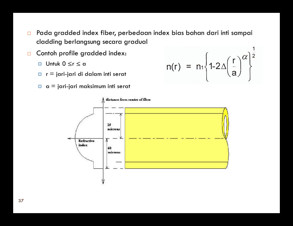
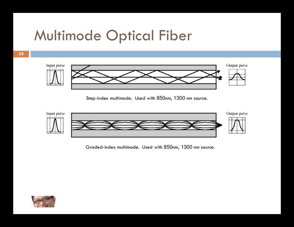
sampai cladding berlangsung secara gradual Contoh profile gradded index: Untuk 0 ≤r ≤ a r = jari-jari di dalam inti serat a = jari-jari maksimum inti serat 37
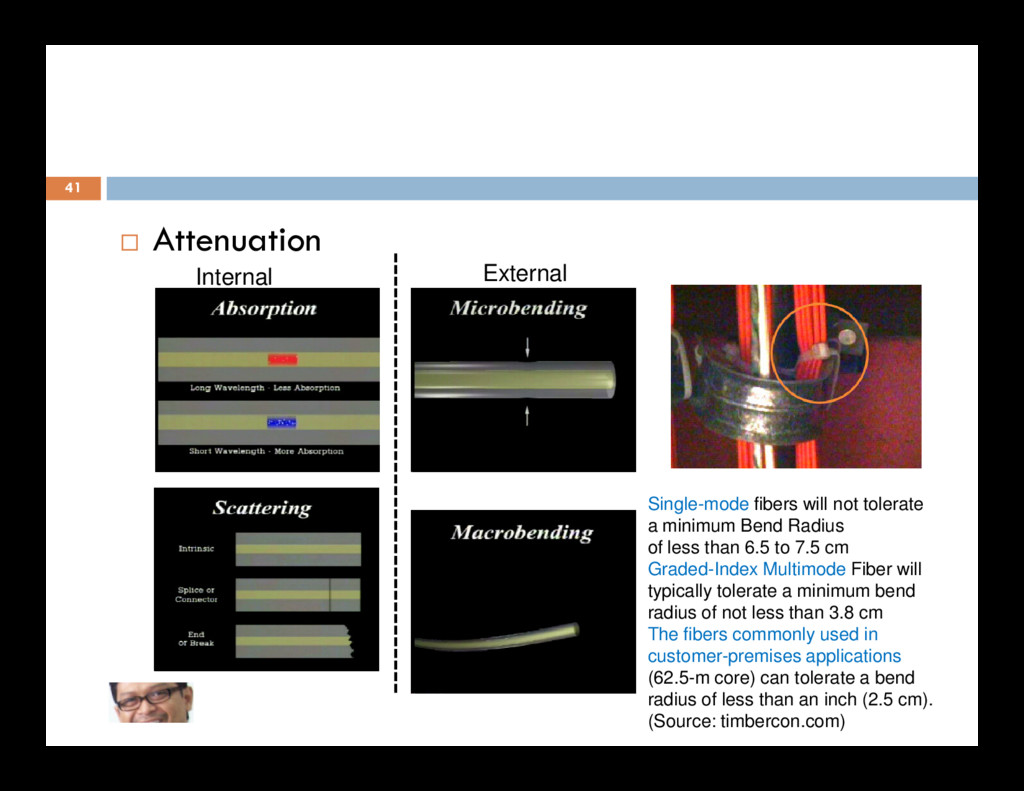
a source such as a laser or an LED is sent down a narrow fiber, it will be changed (degraded) by its passage down the fiber It will emerge (depending on the distance) much weaker lengthened in time (“smeared out”), and 40 lengthened in time (“smeared out”), and distorted in other ways The reasons for the above are as follows: Attenuation Maximum Power Polarization Dispersion Noise
minimum Bend Radius of less than 6.5 to 7.5 cm Graded-Index Multimode Fiber will typically tolerate a minimum bend radius of not less than 3.8 cm The fibers commonly used in customer-premises applications (62.5-m core) can tolerate a bend radius of less than an inch (2.5 cm). (Source: timbercon.com)
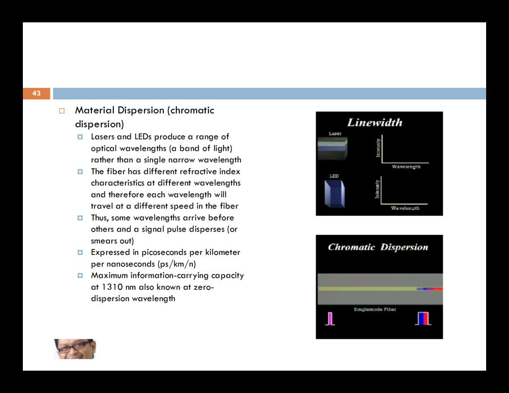
of optical wavelengths (a band of light) rather than a single narrow wavelength The fiber has different refractive index characteristics at different wavelengths and therefore each wavelength will 43 and therefore each wavelength will travel at a different speed in the fiber Thus, some wavelengths arrive before others and a signal pulse disperses (or smears out) Expressed in picoseconds per kilometer per nanoseconds (ps/km/n) Maximum information-carrying capacity at 1310 nm also known at zero- dispersion wavelength
to take many different paths or “modes” as it travels within the fiber The distance traveled by light in each mode is different from the 44 each mode is different from the distance travelled in other modes Therefore, some components of the pulse will arrive before others Not issue in single mode fiber
the length of the fiber, a fiber Information carrying capacity is often characterized by its bandwidth-distance product, often expressed in units of MHz×km. This value is a product of bandwidth and distance because 45 This value is a product of bandwidth and distance because there is a trade off between the bandwidth of the signal and the distance it can be carried For example, a common multimode fiber with bandwidth- distance product of 500 MHz×km could carry a 500 MHz signal for 1 km or a 1000 MHz signal for 0.5 km. ET2080 Jaringan Telekomunikasi
out of the work area. If fiber particles are ingested they can cause internal hemorrhaging Wear disposable aprons to minimize fiber particles on your clothing Fiber particles on your clothing can later get into food, drinks, and/or be ingested by other means Always wear safety glasses with side shields and protective gloves Treat fiber optic splinters the same as you would glass splinters. Never look directly into the end of fiber cables until you are positive that there is no light source at the other end Use a fiber optic power meter to make certain the fiber is dark. When using an optical tracer or continuity 48 Use a fiber optic power meter to make certain the fiber is dark. When using an optical tracer or continuity checker, look at the fiber from an angle at least 6 inches away from your eye to determine if the visible light is present.. Only work in well ventilated areas Contact wearers must not handle their lenses until they have thoroughly washed their hands. Do not touch your eyes while working with fiber optic systems until they have been thoroughly washed Keep all combustible materials safely away from the curing ovens Put all cut fiber pieces in a safe place. Thoroughly clean your work area when you are done Do not smoke while working with fiber optic systems. Source: http://www.jimhayes.com/
transmission, an antenna radiates electromagnetic radiation in the air 52 For reception, the antenna picks up electromagnetic waves from the surrounding medium The antenna plays a key role
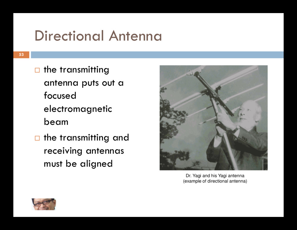
and can be received by many antennas 54 antennas In general, the higher the frequency of a signal, the more it is possible to focus it into a directional beam
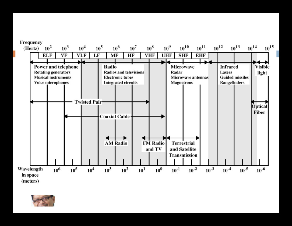
40 GHz are referred to as microwave frequencies 2 GHz to 40 GHz wavelength in air is 0.75cm to 15cm 55 wavelength in air is 0.75cm to 15cm wavelength = velocity / frequency highly directional beams are possible suitable for point-to-point transmission 30 MHz to 1 GHz suitable for omnidirectional applications
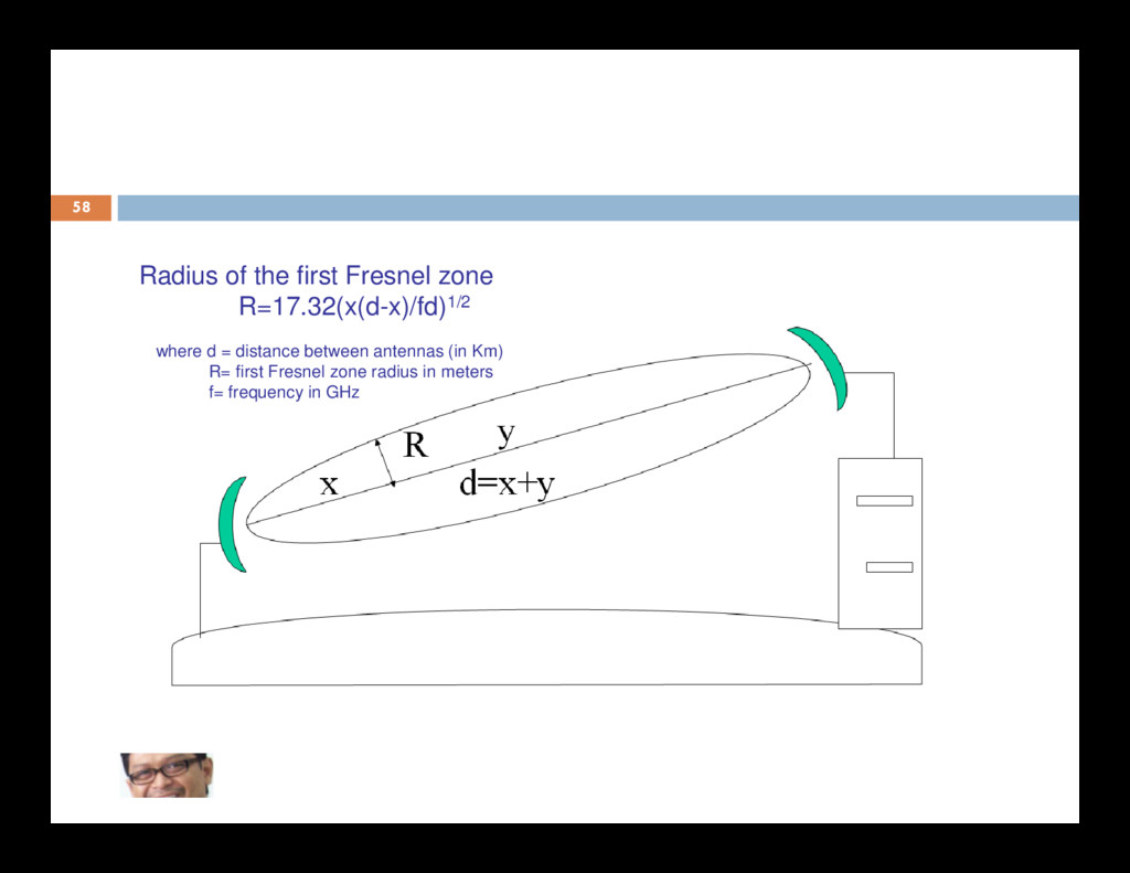
microwaves must be transmitted in a straight line and that no obstructions can exists, such as buildings or 57 exists, such as buildings or mountains, between microwave stations. The Fresnel Zone must be clear of all obstructions.
Range Data Rate 824 - 894 MHz Analog cell phones (AMPS) 20 km per cell 13 kbps/channel 902-928 MHz License free in North America 902-928 MHz License free in North America 1.7 - 2.3 GHz PCS digital cell phones < 1 km per cell 1.8 GHz GSM digital cell phones 16 kbps/channel 2.400-2.484 GHz global license free band 2.4 GHz 802.11, Lucent WaveLAN 100 m - 25 km 2 - 11 Mbps 2.45 GHz Bluetooth about 10 m 1 Mbps 4 - 6 GHz commercial (telecomm.) 40 - 80 km 100 Mbps Infrared short distance line of sight 5 - 100 m 1 Mbps
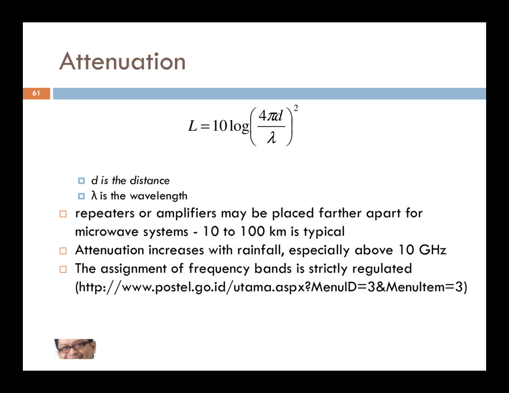
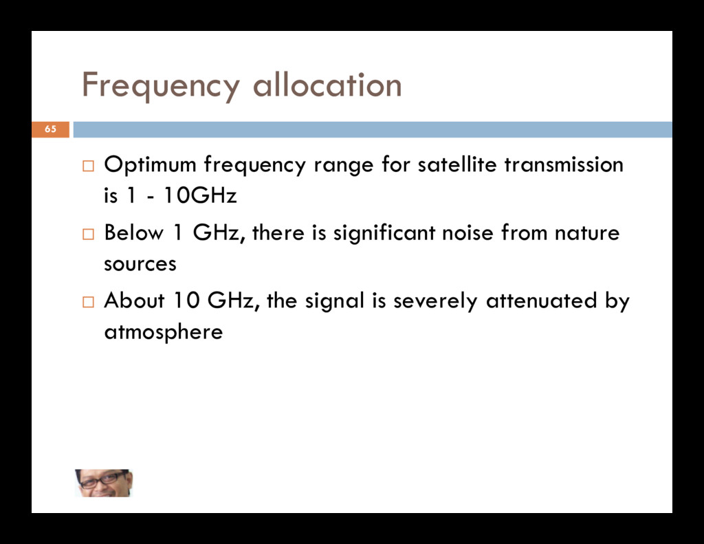
2 4 log 10 = λ πd L λ is the wavelength repeaters or amplifiers may be placed farther apart for microwave systems - 10 to 100 km is typical Attenuation increases with rainfall, especially above 10 GHz The assignment of frequency bands is strictly regulated (http://www.postel.go.id/utama.aspx?MenuID=3&MenuItem=3)
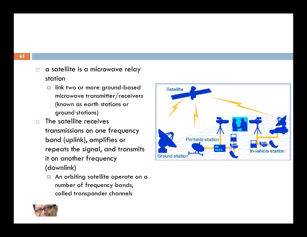
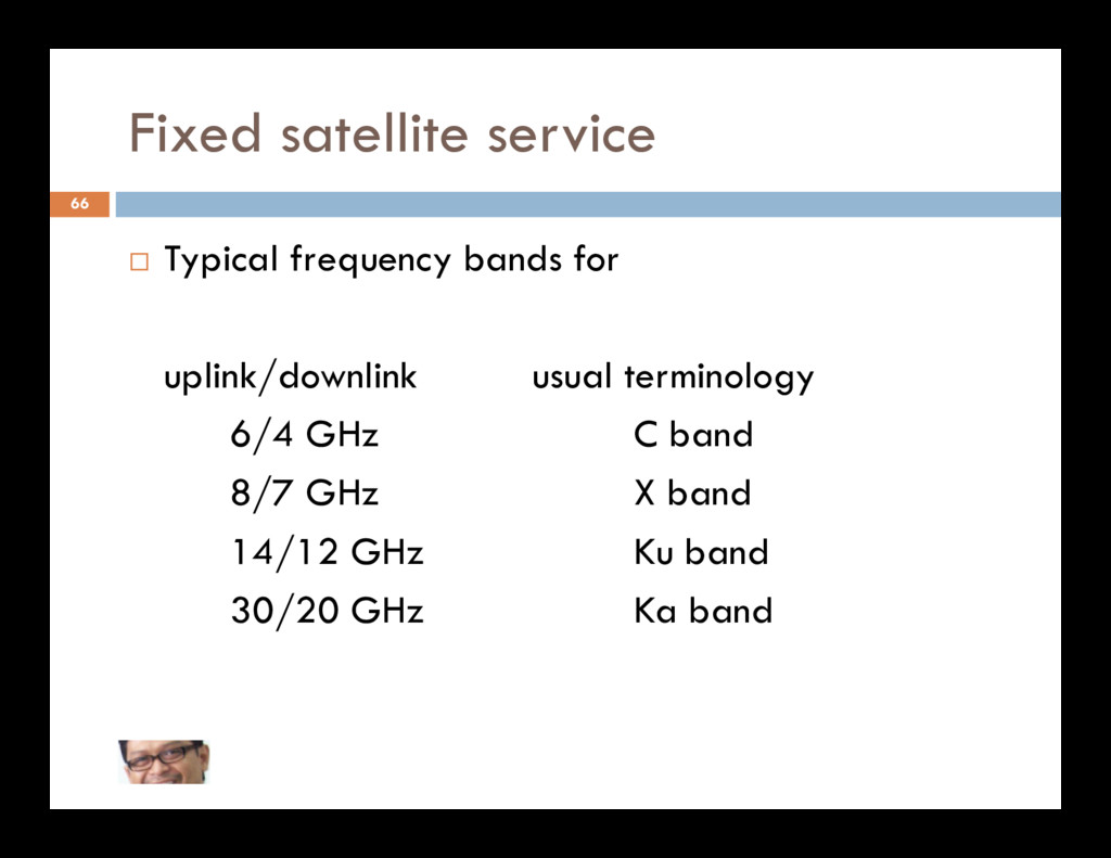
more ground-based microwave transmitter/receivers (known as earth stations or ground stations) The satellite receives 63 The satellite receives transmissions on one frequency band (uplink), amplifies or repeats the signal, and transmits it on another frequency (downlink) An orbiting satellite operate on a number of frequency bands, called transponder channels
satellite ground station with a dish antenna that is smaller than 3 meters. Most VSAT antennas range from 75 cm to 1.2 m. 64 Data rates typically range from 56 Kbit/s up to 4 Mbit/s VSATs access satellites in geosynchronous (geostationary) orbit (to relay data from small remote earth stations (terminals) to other terminals (in mesh configurations) or master earth station "hubs" (in star configurations).
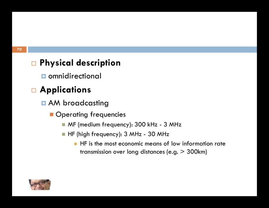
frequencies MF (medium frequency): 300 kHz - 3 MHz HF (high frequency): 3 MHz - 30 MHz HF is the most economic means of low information rate transmission over long distances (e.g. > 300km)
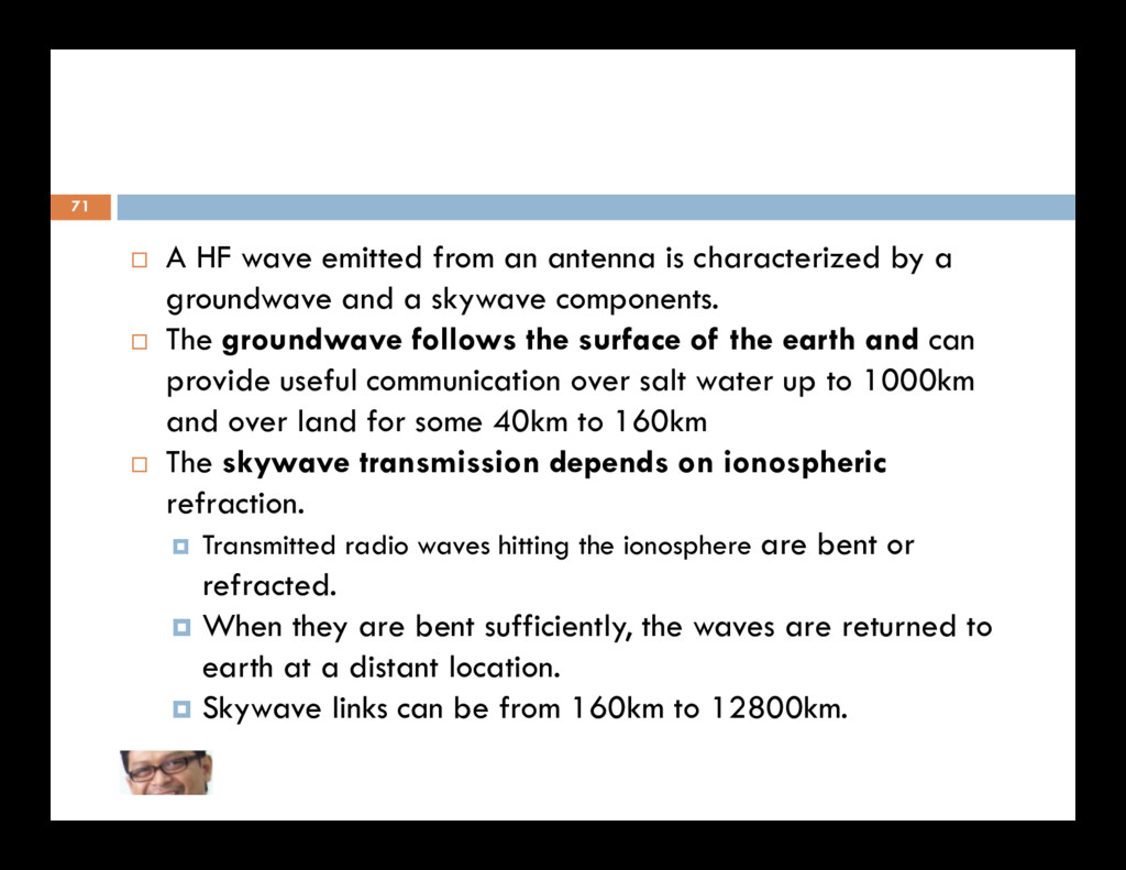
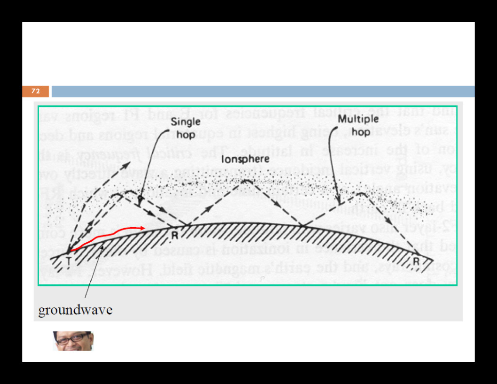
a groundwave and a skywave components. The groundwave follows the surface of the earth and can provide useful communication over salt water up to 1000km and over land for some 40km to 160km 71 and over land for some 40km to 160km The skywave transmission depends on ionospheric refraction. Transmitted radio waves hitting the ionosphere are bent or refracted. When they are bent sufficiently, the waves are returned to earth at a distant location. Skywave links can be from 160km to 12800km.
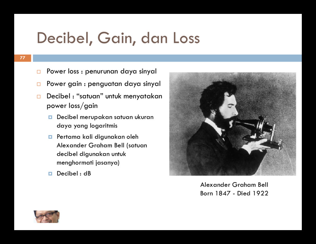
sinyal Power gain : penguatan daya sinyal Decibel : “satuan” untuk menyatakan power loss/gain Decibel merupakan satuan ukuran daya yang logaritmis daya yang logaritmis Pertama kali digunakan oleh Alexander Graham Bell (satuan decibel digunakan untuk menghormati jasanya) Decibel : dB Alexander Graham Bell Born 1847 - Died 1922
in dB gdB = 10 log (Pout /Pin ) Loss L = Pin /Pout Loss in dB LdB = 10 log (Pin /Pout ) Overall Gain g = g1 *g2 Overall Gain in dB gdB = g1(dB) + g2(dB) Contoh: - Bila daya output 10 Watt dan daya input 1 Watt, maka Gain = 10 dB - Bila daya input 10 Watt dan daya output 1 Watt, maka Loss = 10 dB (atau Gain = -10 dB)
melihat penerapan dB untuk menyatakan perbandingan daya Bagaimana cara menyatakan level daya absolut menggunakan dB? menggunakan dB? Gunakan suatu daya referensi
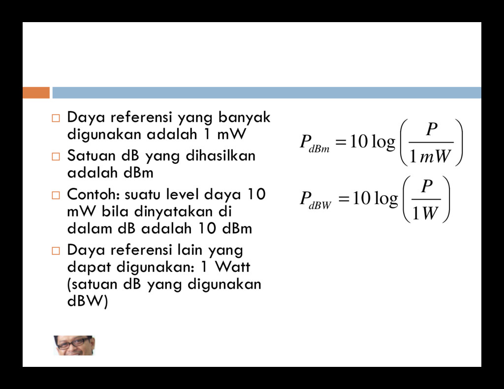
yang dihasilkan adalah dBm Contoh: suatu level daya 10 = = P P mW P P dBm log 10 1 log 10 80 Contoh: suatu level daya 10 mW bila dinyatakan di dalam dB adalah 10 dBm Daya referensi lain yang dapat digunakan: 1 Watt (satuan dB yang digunakan dBW) = W P P dBW 1 log 10
+30 dBm Gain antena = 30 dB Redaman link = 110 dB Daya diterima terima P2,dBm = +30 dBm + 30 dB –110 dB +30 dB = –20 dBm Bila dinyatakan di dalam Watt P2 = 10 μW.
adalah Neper 1 Neper (Np) = 8,685889638 dB 1 Neper (Np) = 8,685889638 dB 1 dB = 0,115129254 Np John Napier or Neper nicknamed Marvellous Merchiston (1550, 1617) Penemu Logaritma