$30 off During Our Annual Pro Sale. View Details »

chips for isoelectric focusing and zone electrophoresis in the free-flow mode

andreas manz
February 02, 2003

chips for isoelectric focusing and zone electrophoresis in the free-flow mode

... talk given at MSB 2003, New Orleans.

andreas manz

February 02, 2003
Tweet

More Decks by andreas manz

Other Decks in Science

Transcript

  1. chips for isoelectric focusing and
    zone electrophoresis in the free-
    flow mode
    Yi Xu, Chao-Xuan Zhang,
    Andreas Manz
    Imperial College, Dept. Chemistry,
    London UK

    View Slide

  2. What should I show you?
    Electrophoresis scaling laws !

    View Slide

  3. separation efficiency
    • Number of theoretical plates is proportional
    to voltage drop
    U
    N 

    View Slide

  4. heating problem
    •Power generated per unit length should be a
    constant
    const
    L
    I
    U


    View Slide

  5. separation efficiency
    •Number of theoretical plates is proportional
    to length / diameter of capillary
    d
    L
    N 

    View Slide

  6. separation time
    •Analysis time is proportional to length *
    diameter of capillary
    d
    L
    t 

    View Slide

  7. 10 fold miniaturization
    100 x faster separation
    1000 x smaller volume
    10 x lower reagent consumption
    identical quality of separation

    View Slide

  8. fluorescence [arb. units]
    time [s]
    0 40 80 120 160
    1 2
    3
    4
    5
    6
    cycle #
    7 8
    t 7 s
    synchr.
    fluorescence [arb. units]
    time [s]
    0 40 80 120 160
    1 2
    3
    4
    5
    6
    cycle #
    7 8
    t 7 s
    synchr.
    fluorescence [arb. units]
    time [s]
    0 40 80 120 160
    1 2
    3
    4
    5
    6
    cycle #
    7 8
    t 7 s
    synchr.
    electrophoresis
    by Franz von Heeren

    View Slide

  9. electrophoresis

    View Slide

  10. Agilent 2100 Bioanalyzer
    electrophoresis

    View Slide

  11. FFE
    principle

    View Slide

  12. FFE
    problem

    View Slide

  13. FFE
    problem
    el. current much larger
    heat dissipation worse

    View Slide

  14. FFE
    chip history 1994
    by Dan Raymond

    View Slide

  15. FFE
    chip history
    by Dan Raymond

    View Slide

  16. FFE
    chip history
    by Dan Raymond

    View Slide

  17. FFE
    chip history
    by Dan Raymond

    View Slide

  18. latest design
    + -

    View Slide

  19. View Slide

  20. latest design
    • volume 240 nL plus micro wells
    • 36 x 20um inlet channels
    • 72 x 20um outlet channels
    • each side 108 x 4um channels
    • separation bed 12.2 x 4.1 mm
    – 15,552 posts
    – 30 x 30 um

    View Slide

  21. View Slide

  22. View Slide

  23. View Slide

  24. diffusion…

    View Slide

  25. electrophoresis
    happens…

    View Slide

  26. very fast
    electrophoresis

    View Slide

  27. problem with posts

    View Slide

  28. 111 ms
    41 ms
    53 ms
    64 ms
    76 ms
    88 ms
    99 ms
    integrating over rectangular area

    View Slide

  29. influence of
    electric field
    separation of 2 amino acids

    View Slide

  30. 0
    200
    400
    600
    800
    0 100 200 300 400 500
    electric field [V/cm]
    migration distance [um]
    migration distance = f (E)

    View Slide

  31. isoelectric focusing (IEF)
    • establish pH gradient
    • establish electric field
    • charge of protein depends on pH
    • mobility is nil at isoelectric point
    • focusing

    View Slide

  32. IEF proof of principle
    12 mm
    0 mm
    4 mm
    4 mm = 500 ms
    angiotensin I, 1.75 kV, 10 uL/min

    View Slide

  33. IEF – two peptides

    View Slide

  34. IEF - IGF-1
    sample concentration
    10-7 M at inlet
    >10-5 M here

    View Slide

  35. IEF – IGF-1
    • sample introduced at 4.1 mm width
    • distance post-post on structure 40 um
    • apparent streamline 10 um
    • preconcentration factor is around
    100x to 400x

    View Slide

  36. IEF chip specific problem
    • side channels contribute >80% of
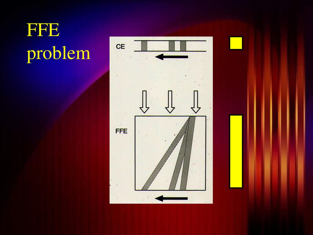
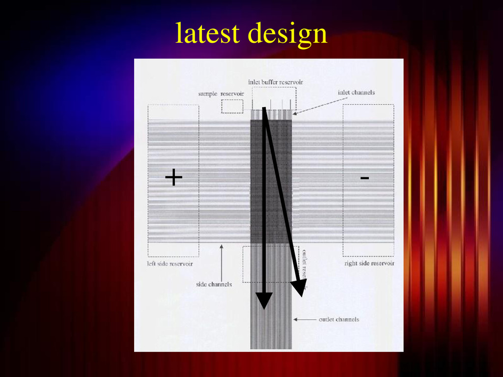
    voltage drop
    • part of the pH gradient will
    therefore be lost
    • buffer reservoirs have to be at
    extreme pH
    • some proteins will not stay in the
    separation area

    View Slide

  37. fluorescence [arb. units]
    time [s]
    0 40 80 120 160
    1 2
    3
    4
    5
    6
    cycle #
    7 8
    t 7 s
    synchr.
    fluorescence [arb. units]
    time [s]
    0 40 80 120 160
    1 2
    3
    4
    5
    6
    cycle #
    7 8
    t 7 s
    synchr.
    fluorescence [arb. units]
    time [s]
    0 40 80 120 160
    1 2
    3
    4
    5
    6
    cycle #
    7 8
    t 7 s
    synchr.
    comparison
    FFE
    CE

    View Slide

  38. conclusions
    • IEF is possible and very fast in
    small 
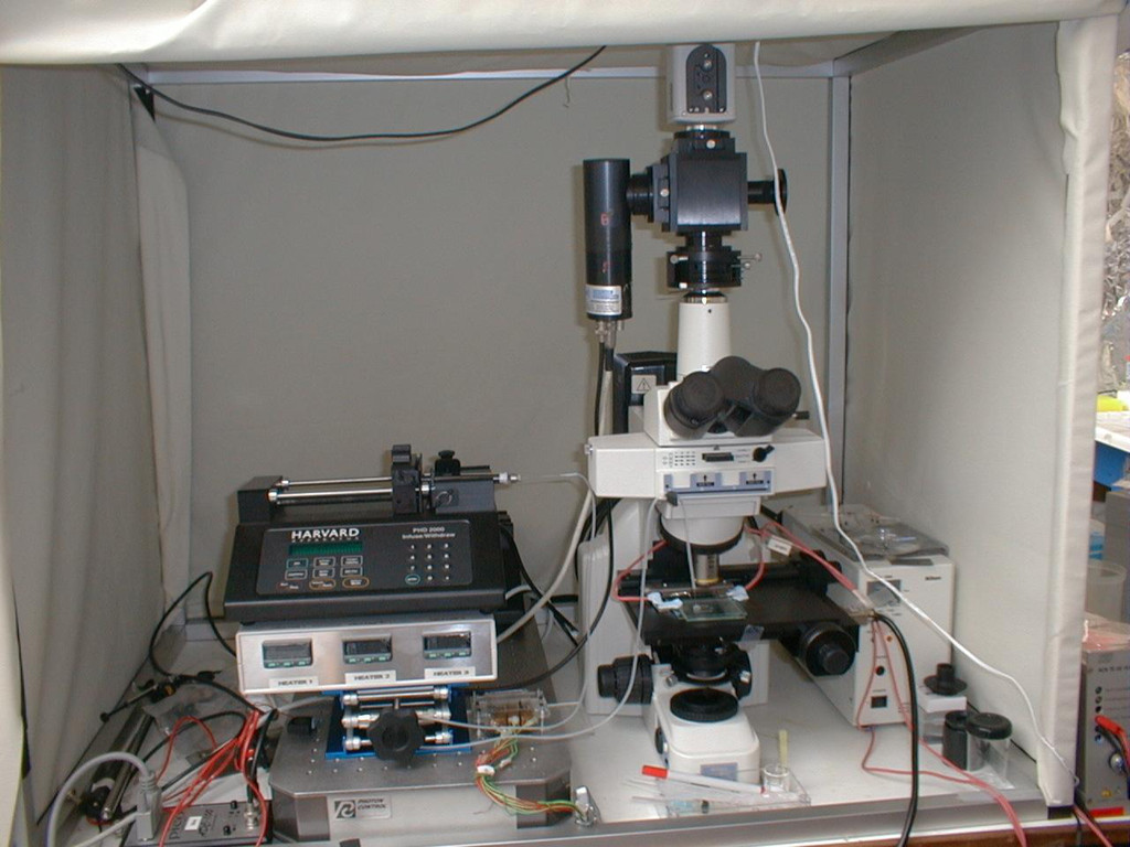
FFE system
    • preconcentration of over 100x is
    possible
    • problems with pH gradient and side
    channels
    • fraction collection has to be done
    • detector has to be attached

    View Slide

  39. Acknowledgment
    EU funding
    BBSRC clean room

    View Slide