Upgrade to Pro — share decks privately, control downloads, hide ads and more …

Image Formation and Radiographic Quality - Dens...

Sponsored · Your Podcast. Everywhere. Effortlessly. Share. Educate. Inspire. Entertain. You do you. We'll handle the rest. →

Image Formation and Radiographic Quality - Density, Contrast, Detail, Distortion | DMLT Notes

Complete notes on Image Formation and Radiographic Image Quality for DMLT 1st Year, BSc Radiology and X-ray Technician students.

Topics Covered:
1. Formation of X-ray Image - Latent Image
2. Factors Affecting Image Formation
3. Radiographic Quality Factors:
- Radiographic Density
- Radiographic Contrast - Subject Contrast, Film Contrast
- Radiographic Detail / Sharpness / Resolution
- Distortion and Magnification - MFD, OFD
4. Factors affecting Density, Contrast, Sharpness
5. Geometrical Factors - Focal Spot Size, SID, OID
6. Image Unsharpness - Motion, Geometric, Photographic

Very useful for DMLT exam, viva and practical. Prepared by Annu Maurya.

Keywords: image formation in radiography, radiographic quality notes, density contrast detail, DMLT 1st year image quality, distortion magnification notes

Avatar for Er. Annu maurya

Er. Annu maurya

September 10, 2026

More Decks by Er. Annu maurya

Other Decks in Education

Transcript

  1. Principles of image formation  Radiographic image formation relies on

    the differential absorption and attenuation of an X-ray beam as it passes through different body tissues to strike an image receptor
  2. 1. X-Ray Generation (The Primary Beam)  Thermionic emission: Heating

    a tungsten filament at the cathode releases free electrons.  Acceleration: High voltage (kVp) propels these electrons toward the positive anode.  Photon production: Electron collision with the anode target produces an outgoing beam of X-ray photons
  3. 2. Interaction with Matter (Attenuation)  Transmission: Photons pass straight

    through low-density or less thick structures (like air) without interacting, creating dark areas on the final image.  Photoelectric effect (Absorption): Incoming photons transfer all their energy to inner-shell electrons and are completely absorbed. This happens more frequently in dense tissues with high atomic numbers (like bone or metal), creating bright/white areas  Compton scattering: Photons interact with outer-shell electrons, lose partial energy, and change direction. This scattered radiation adds unwanted fog and reduces image contrast
  4. 3. Remnant Radiation (Exit Beam)  The remaining beam exiting

    the patient is called the remnant or exit radiation.  It consists of a pattern of transmitted and scattered photons that structurally represent the internal anatomy
  5. 4. Detection and Image Recording  Image receptor: The exit

    beam strikes a detector, which can be a digital flat-panel system, a computed radiography phosphor plate, or traditional film-screen.  Signal conversion: The detector converts the radiation pattern into a latent or electronic image, which is then processed into the visible grayscale radiograph used for medical diagnosis
  6. factors affecting image quality in radiology  Image quality in

    radiography depends on a balance of fundamental photographic and geometric factors that determine how clearly internal structures are displayed
  7. The four primary characteristics of image quality are evaluated through

     Contrast: The difference in density or brightness between adjacent areas.  Spatial Resolution: The sharpness and clarity of small structural details.  Noise: Random, unwanted fluctuations or graininess that obscure the true signal.  Distortion: Misrepresentation of the true size or shape of an object
  8. 1. X-Ray Beam and Exposure Parameters (Technique Factors)  Kilovoltage

    Peak (kVp): Controls the energy and penetrating power of the X-ray beam. Higher kVp lowers image contrast (more shades of gray) and increases scatter, while lower kVp yields high contrast (black-and-white). [1, 2]  Milliampere-Seconds (mAs): Controls the total quantity of X-ray photons produced. Higher mAs increases image density or signal and reduces quantum noise, but increases patient radiation dose
  9. 2. Geometry and Positioning  Focal Spot Size: Smaller focal

    spots in the X-ray tube reduce geometric unsharpness (penumbra) and improve spatial resolution. [1, 2]  Distances (SID and OID): Increasing the Source-to-Image Distance (SID) reduces size distortion, whereas increasing the Object-to-Image Distance (OID) magnifies the object and blurs edges. [1, 2]  Alignment: Improper alignment of the beam, object, or receptor causes shape distortion like elongation or foreshortening. Patient motion during exposure causes severe motion blur
  10. 3. Scatter Control and Patient Subject  Patient Thickness and

    Density: Thicker or denser body parts absorb more radiation, changing the remnant beam and requiring adjusted exposure factors.  Scattered Radiation: Scatter degrades contrast and creates a foggy appearance. Using collimation or an anti-scatter grid removes scatter and enhances clarity.
  11. 4. Receptor and Processing Performance  Detector Properties: In digital

    systems, smaller detector element (pixel) size improves spatial resolution.  Image Processing: Advanced computer algorithms and post-processing tools adjust brightness, contrast, and edge enhancement to optimize the final diagnostic view. For a detailed medical breakdown, consult the StatPearls X-Ray Quality Assurance Guide
  12. Geometric factors in radiography  Geometric factors in radiography determine

    the sharpness, size, and shape of an image based on how the radiation beam travels from the source through the object to the detector
  13. Geometric Factors  Focal Spot Size (\(F\)): The physical area

    on the X-ray tube anode where X-rays are produced. Smaller focal spots create sharper images with less blur, while larger ones increase blurring.  Source-to-Image Distance (\(SID\)): The total distance from the X-ray source to the image detector. Increasing SID improves image sharpness and reduces magnification
  14.  Object-to-Image Distance (\(OID\)): The distance between the object being

    imaged and the detector. Increasing OID increases magnification and geometric blurring.  Source-to-Object Distance (\(SOD\)): The distance from the X-ray source to the object. Increasing SOD decreases magnification and unsharpness.  Alignment and Angulation: The positioning of the tube, object, and detector. Misalignment causes shape distortion like elongation or foreshortening
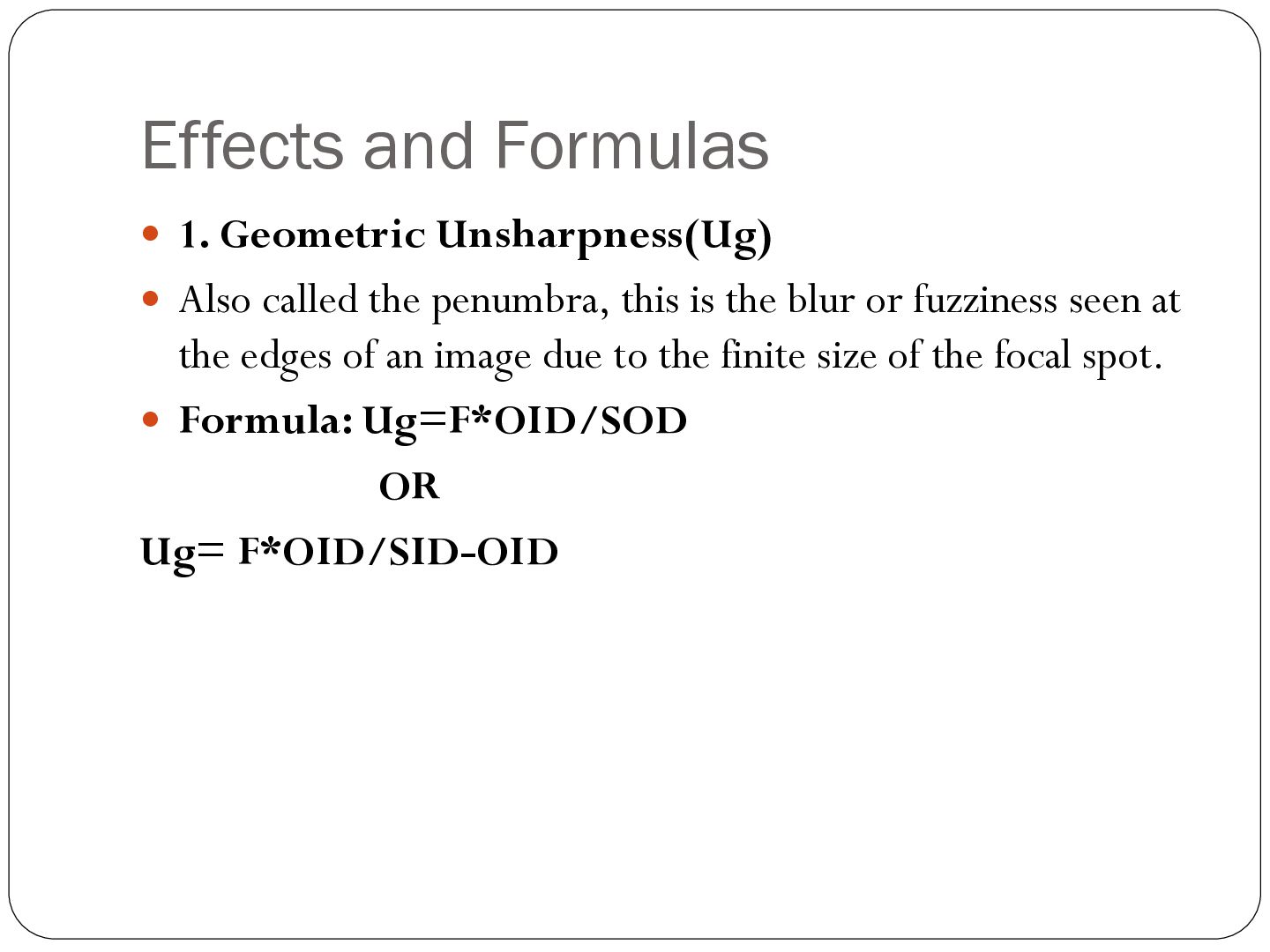
  15. Effects and Formulas  1. Geometric Unsharpness(Ug)  Also called

    the penumbra, this is the blur or fuzziness seen at the edges of an image due to the finite size of the focal spot.  Formula: Ug=F*OID/SOD OR Ug= F*OID/SID-OID
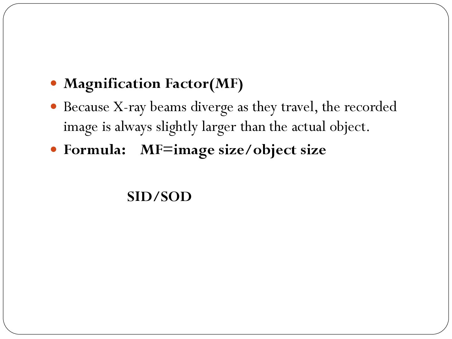
  16.  Magnification Factor(MF)  Because X-ray beams diverge as they

    travel, the recorded image is always slightly larger than the actual object.  Formula: MF=image size/object size SID/SOD
  17. image artifacts in radiography  Image artifacts in radiography are

    unwanted or artificial marks, shadows, or distortions on an X-ray image that do not represent actual anatomical structures or pathology
  18. Common Types of Radiographic Artifacts  Motion Artifact: Blurred or

    distorted image outlines caused by patient movement during the X-ray exposure.  External Radiopaque Objects: Superimposed highdensity items left on or near the patient, such as jewelry, zippers, buttons, or hair braids.  Grid Cut-Off: An uneven decrease in optical density or brightness across the image caused by improper alignment or centering of the X-ray grid
  19.  Double Exposure (Twin Artifact): The accidental superimposition of two

    distinct anatomical exposures onto a single film or computed plate.  Backscatter: The reflection of X-ray photons off the back of the cassette or examination table, revealing an outline of internal electronics or hinges on the final image.  Dead Pixel Artifact: Non-functional detector elements in digital radiography that manifest as isolated sharp white or black dots or speckles
  20.  Static Electricity: Jagged, dark, tree-like, or spider-web branching lines

    caused by friction or low humidity during film handling.  Processing and Roller Marks: Chemical streaks, scratches, or regular line patterns caused by dirty or malfunctioning automatic film processors.
  21. Causes of Radiographic Artifacts Patient-Related Causes: 1. Motion: Patient movement

    during exposure leads to blurring or distorted images. 2. Radiopaque Objects: Clothing buttons, jewelry, piercings, or braids block X-rays and leave unwanted shadows
  22. Hardware and Equipment Causes:  Dead Pixels: Nonfunctional elements on

    a digital detector array appear as tiny black or white spots.  Plate Damage: Scratches, cracks, or dust on computed radiography (CR) imaging plates or intensifying screens create white lines or clear spots.  Grid Cut-Off: Misalignment of the X-ray grid leads to uneven absorption and light or dark areas on the film or detector.  Backscatter: X-rays reflecting off metal components behind the detector can outline internal electronics on the image.
  23. Operator and Exposure Technique Causes:  Superimposing two structures on

    the same film or plate because it was exposed twice.  Improper Collimation: Incorrect field sizing can confuse the system's values of interest, yielding washed-out or severely underexposed images.  Parallax Effect: Tilting or off-centering the object relative to the central X-ray beam distorts measurements and shapes.
  24. Processing and Software Causes  Chemical or Roller Marks: Dirty

    rollers, improper washing, or chemical splashes during traditional film processing cause streaks and spots.Ghosting (Detector Lag): A residual latent image from a previous high-exposure shot remains visible on the next frame due to trapped charge.Stitching Errors: Poor software alignment when merging two separate image acquisitions (like in long-leg or full-spine imaging)