Upgrade to Pro — share decks privately, control downloads, hide ads and more …

A System-Theoretic Safety Engineering Approach for Software-Intensive Systems

A System-Theoretic Safety Engineering Approach for Software-Intensive Systems

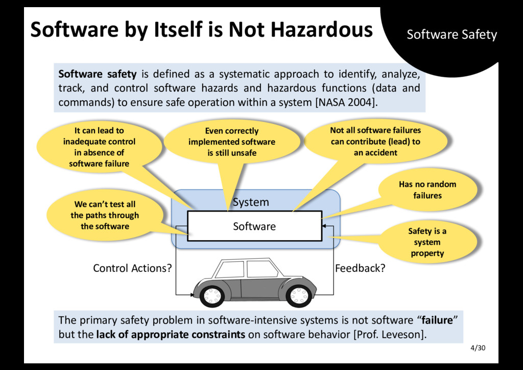
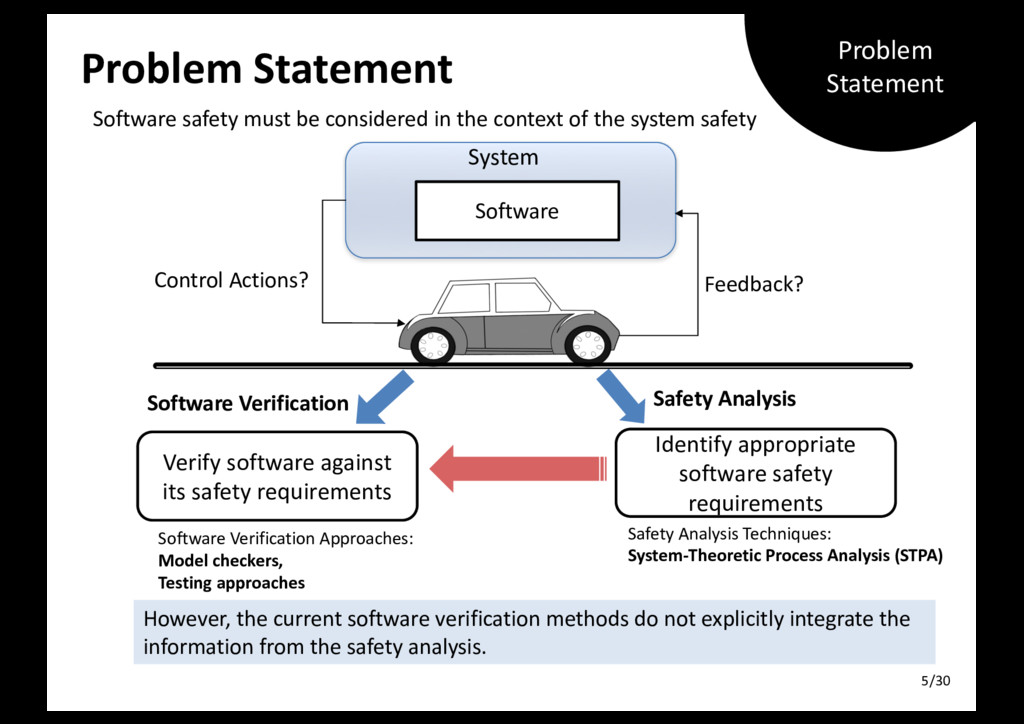
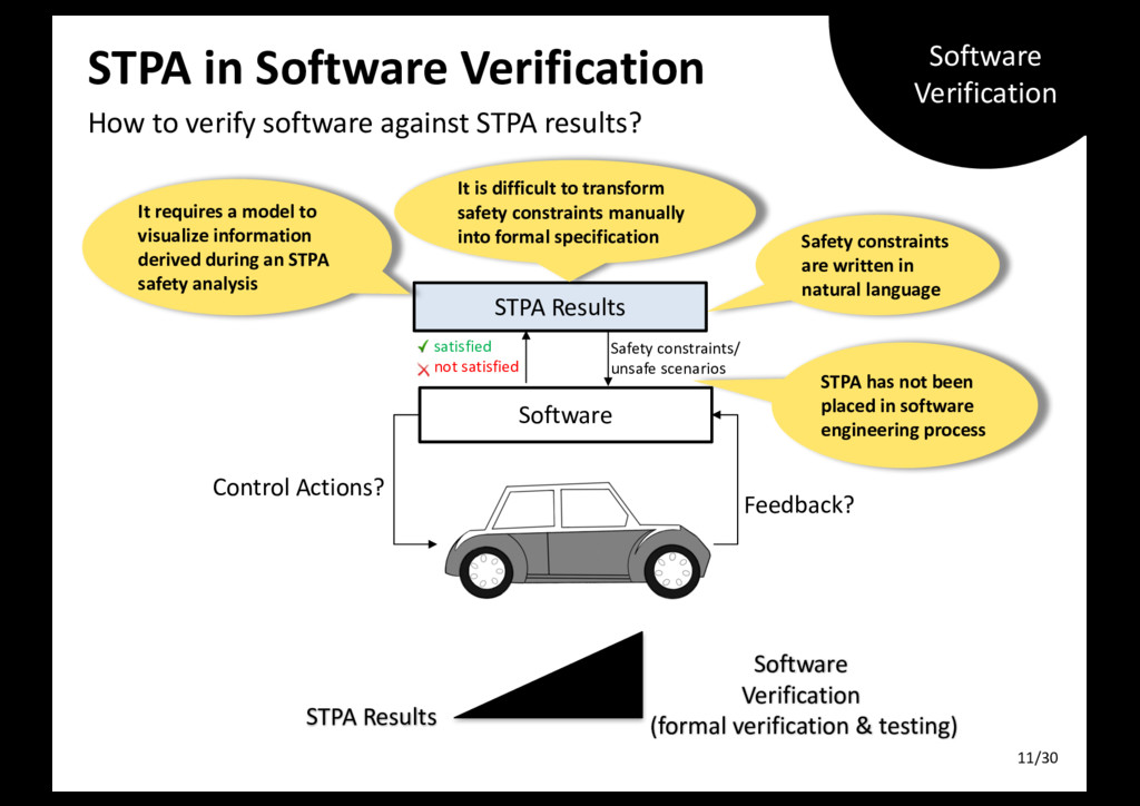
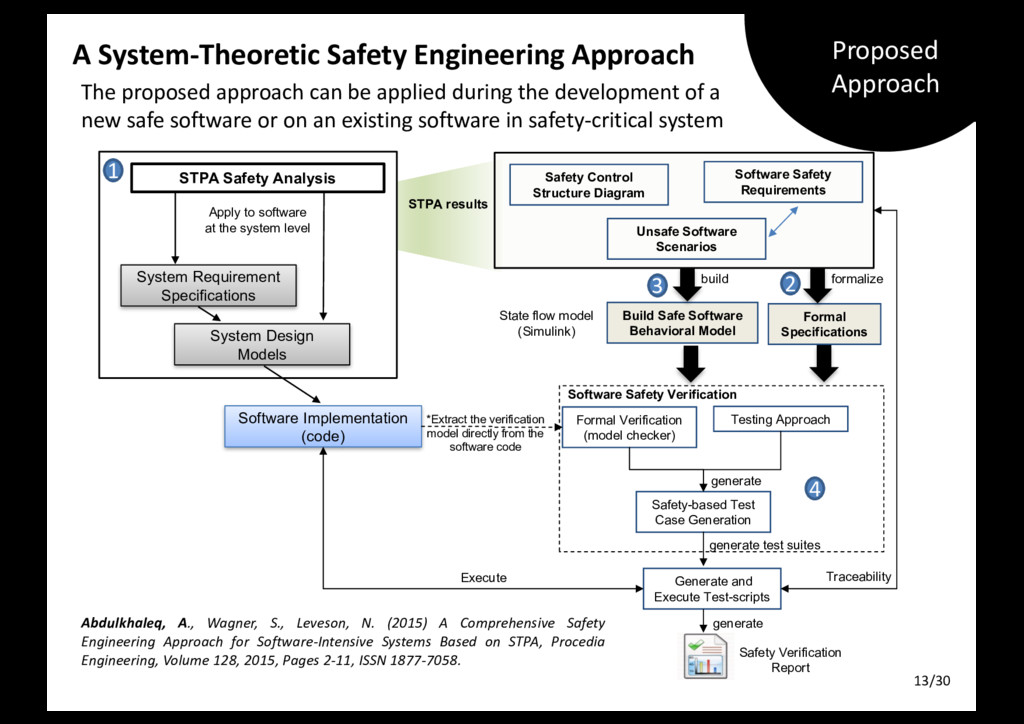
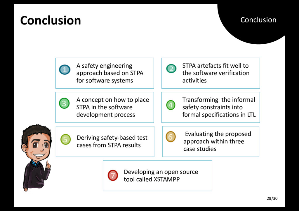
In the software development process, formal verification and functional testing are complementary approaches which are used to verify the functional correctness of software; however, even perfectly reliable software could lead to an accident. The correctness of software cannot ensure the safe operation of safety-critical software systems. Therefore, developing safety-critical software requires a more systematic software and safety engineering process that enables the software and safety engineers to recognize the potential software risks. For this purpose, this dissertation introduces a comprehensive safety engineering approach based on STPA for Software-Intensive Systems, called STPA SwISs, which provides seamless STPA safety analysis and software safety verification activities to allow the software and safety engineers to work together during the software development for safety-critical systems and help them to recognize the associated software risks at the system level.

More Decks by Dr. rer. nat Asim Abdulkhaleq

Other Decks in Research

Transcript

  1. Ph.D. Dissertation Defense A System-Theoretic Safety Engineering Approach for Software-Intensive

    Systems Asim Abdulkhaleq Stuttgart, February 6th 2017 University of Stuttgart @AbdulkhaleqAsim 06-02-2017 Ph.D. Defense Committee: Prof. Dr. Stefan Wagner Prof. Dr. Nancy Leveson Prof. Dr. Dr. h. c. Frank Leymann Prof. Dr. Ulrich Hertrampf Prof. Dr. Ralf Küsters www.XSTAMPP.de 1/30
  2. Software Safety Software Safety? v Today’s safety-critical systems are increasingly

    reliant on software v E.g. Autonomous vehicles will replace the driver tasks by software functions to make traffic more comfortable. Software Control Actions? Feedback? > 100 million lines of code > 70 Electronic Control Units (ECUS) > 50 software functions Autonomous vehicle Motivation 2/30
  3. Agenda v Motivation v Introduction Ø Problem Statement Ø Research

    Objectives Ø Contributions v Background Ø Safety Analysis Techniques Ø Software Verification v Proposed Approach v Illustrative Example: Adaptive Cruise Control System with Stop-and-Go function v Conclusion & Future Work Agenda 3/30
  4. System 4/30 Software by Itself is Not Hazardous Software Control

    Actions? Feedback? Not all software failures can contribute (lead) to an accident We can’t test all the paths through the software The primary safety problem in software-intensive systems is not software “failure” but the lack of appropriate constraints on software behavior [Prof. Leveson]. It can lead to inadequate control in absence of software failure Even correctly implemented software is still unsafe Has no random failures Safety is a system property Software safety is defined as a systematic approach to identify, analyze, track, and control software hazards and hazardous functions (data and commands) to ensure safe operation within a system [NASA 2004]. Software Safety
  5. System Software Control Actions? Feedback? Software safety must be considered

    in the context of the system safety Problem Statement Verify software against its safety requirements Software Verification Approaches: Model checkers, Testing approaches Software Verification Identify appropriate software safety requirements Safety Analysis Techniques: System-Theoretic Process Analysis (STPA) Safety Analysis However, the current software verification methods do not explicitly integrate the information from the safety analysis. Problem Statement 5/30
  6. Research Objectives To develop a safety engineering approach based on

    STPA which offers seamless safety analysis and software verification activities to help software and safety engineers in: Ø deriving the appropriate software safety requirements Ø formally verifying them, and Ø generating safety-based test cases to recognize the associated software risks. To develop an open-source tool to support the proposed approach Research Objectives 6/30
  7. Developing a safety engineering approach based on STPA Providing formal

    definitions and algorithms Developing an open-source tool called XSTAMPP Evaluating the proposed approach: •Developing a safe software simulator of ACC. •Evaluating the BMW Active Cruise Control system. •Evaluating the Continental autonomous vehicle. Contributions 1 2 3 4 Contributions 7/30
  8. Why STPA (System-Theoretic Process Analysis)? v Limitations: ❌ They assume

    that accidents are caused by component failures (Reliability Theory). ❌ They are not adequate to address new accidents caused by component interactions, software and human errors [Leveson 2011]. ❌ Some of them do not provide any kind of system model. 1940 1950 1960 1970 1980 1990 FMEA FTA HAZOP ETA [Leveson 2016] v There are over 100 different hazard analysis approaches. Traditional Techniques 8/30
  9. STPA Safety Analysis Approach v STPA (System-Theoretic Process Analysis) Ø

    Developed by Prof. Leveson at MIT, USA, 2004 Ø Built on STAMP (System-Theoretic Accident Model and Processes) model based on system and control theory rather than reliability. Ø Treats safety as dynamic control problem rather than component failure problem Human/Automated Controller Actuators Sensors Controlled Process Control Actions Measured Variables Process Outputs Process Inputs Disturbances Feedback Variables Controlled Variables A generic control loop (Leveson 2011) Monitored Variables Process Model Automated Controller Control Algorithm Feedback Variables Starting Point STPA/STAMP 9/30
  10. STPA Approach Process Safety Analysis Report Causal Scenarios System specification

    and design models Input Start Develop Control Structure Diagram Hierarchical Control Structure Diagram STPA Step 1: Identify unsafe control actions STPA Step 2: Identify how each unsafe control action could occur Hierarchical Control Structure with process model System-Level Accidents, related hazards, design and safety constraints Unsafe Control Actions Corresponding Safety Constraints Fundamentals New/Refined Safety Constraints Results STPA Process (Causal Factors) STPA Define Analysis Scope STPA Process 10/30
  11. STPA in Software Verification How to verify software against STPA

    results? Software Verification (formal verification & testing) STPA Results Software Control Actions? Feedback? STPA has not been placed in software engineering process Safety constraints are written in natural language satisfied not satisfied STPA Results Safety constraints/ unsafe scenarios It is difficult to transform safety constraints manually into formal specification It requires a model to visualize information derived during an STPA safety analysis Software Verification 11/30
  12. build A System-Theoretic Safety Engineering Approach The proposed approach can

    be applied during the development of a new safe software or on an existing software in safety-critical system Apply to software at the system level Safety Control Structure Diagram STPA Safety Analysis Unsafe Software Scenarios Software Safety Requirements System Requirement Specifications System Design Models Software Implementation (code) Build Safe Software Behavioral Model Formal Verification (model checker) Testing Approach State flow model (Simulink) Safety-based Test Case Generation Generate and Execute Test-scripts generate generate test suites formalize generate Traceability Execute *Extract the verification model directly from the software code STPA results Software Safety Verification 1 2 3 4 Safety Verification Report Formal Specifications Abdulkhaleq, A., Wagner, S., Leveson, N. (2015) A Comprehensive Safety Engineering Approach for Software-Intensive Systems Based on STPA, Procedia Engineering, Volume 128, 2015, Pages 2-11, ISSN 1877-7058. Proposed Approach 13/30
  13. u System-Level Hazards: H-1: ACC software does not maintain safe

    distance from front vehicle [AC-1]. u System-Level Accidents: AC-1: ACC vehicle collides with target vehicle. ACC Software Simulator We develop a software simulator of ACC How to derive the safety requirements of ACC software controller at the system level and generate the safety-based test cases? Adaptive Cruise Control System (ACC): is a well-known automotive system which has strong safety requirements. ACC adapts the vehicle’s speed to traffic environment based on a long range forward-radar sensor which is attached to the front of a vehicle. ACC Vehicle Target Vehicle 14/30 Illustrative Example
  14. Safety Control Structure Diagram High-level control structure of a particular

    system What are the potential unsafe control actions? Operator Actuators Speed Sensor Controlled Process Accelerate Decelerate FullyStop currentspeed Process Outputs Process Inputs Disturbances frontdistance Motor forces Ultrasonic Sensor speed Motor 1 Motor 2 Sensor Controller Actuator Controlled Process Legends: ACC Stop-and-Go Function Software Controller desiredspeed safedistance On/Off Control Structure Diagram 15/30
  15. Unsafe Control Actions Providing or not Providing a control action

    causes a hazard Control Actions Not Providing causes hazards Providing causes hazards Wrong timing or order causes hazards Stopped too soon or applied too long Accelerate The ACC software does not accelerate the speed when the robot vehicle ahead is so far in the lane. [Not hazardous] UCA1.1: The ACC software accelerates the speed of the robotic vehicle when the robotic vehicle ahead is too close [H-1] [H-2] UCA1.2. The ACC software accelerates the speed before the robot vehicle ahead starts to move again [H-1] [H-2]. N/A Corresponding safety constraints: SC1.1: The ACC software must not provide the acceleration signal when the robotic vehicle ahead is too close. Translate each hazardous item ACC Stop-and-Go Function Software Controller Accelerate Decelerate FullyStop Motor 1 Motor 2 Actuators Unsafe Control Actions Table 16/30
  16. Process Model & Variables A model required to determine the

    environmental & system variables that affect the safety of the control actions. Operator Actuators Speed sensor Accelerate Decelerate FullyStop currentspeed frontdistance desiredspeed Ultrasonic sensor speed Motor 1 Motor 2 Controlled Process Process Outputs Process Inputs Motor forces ACC Stop-and-Go Function Software Controller safedistance On/Off Disturbances currentspeed = 0 > minSpeed == desiredspeed > desiredspeed < desiredspeed Process Model ACCMode Standby Resume Cruise Follow Stop timeGap = 0 <= (deltaX +safetyTimeGap) > (deltaX + safetyTimeGap) > safetyTimeGap < safetyTimeGap frontdistance <= 0 > 0 Power ACCOff ACCOn 17/30 Process Model
  17. UCA 1.1: The ACC software accelerates the speed of the

    robotic vehicle when the robotic vehicle ahead is too close [H-1] [H-2] Generating the Unsafe Control Actions (UCA) Extended Approach to STPA: Identify unsafe control actions in the STPA Step 1 based on the combination of process model variables (Dr. John Thomas, MIT). Control Actions Process Model Variables Hazardous? (any time, too early, too late) Accelerate currentspeed timeGap ACCMode >mindspeed <△ TimeGap + safeTimeGap follow No <=desiredspeed TimeGap=0 follow Yes (H1, H2) Refined UCA 1.1 : The ACC software controller provided an acceleration signal when the current speed is less or equal to the desired speed, time gap is equal to 0 and the ACC system in follow mode. Refined Safety Constraint RSC1.1 : The ACC software controller must not provide an acceleration signal when the current speed is less or equal to the desired speed, time gap is equal to 0 and the ACC system in follow mode. Automatically generate corresponding safety constraints Automatically generate unsafe control actions Context Table 18/30
  18. Causal Factors & Scenarios How each unsafe control action could

    occurs in the system UCA 1.1: The ACC software accelerates the speed of the robotic vehicle when the robotic vehicle ahead is too close [H-1] [H-2] Actuators Speed sensor Accelerate Decelerate FullyStop currentspeed frontdistance desiredspeed Ultrasonic sensor speed Motor 1 Motor 2 Controlled Process Process Outputs Process Inputs Motor forces ACC Stop-and-Go Function Software Controller safedistance On/Off Disturbances currentspeed = 0 > minSpeed == desiredspeed > desiredspeed < desiredspeed Process Model ACCMode Standby Resume Cruise Follow Stop timeGap = 0 <= (deltaX +safetyTimeGap) > (deltaX + safetyTimeGap) > safetyTimeGap < safetyTimeGap frontdistance <= 0 > 0 Power ACCOff ACCOn 1. Unsafe Inputs from Higher Levels 2. Unsafe Algorithm 3. Incorrect Process Implementation 4. Incorrect - Process Models 5. Feedback Wrong or Missing STPA Step 2 19/30
  19. Fundamentals Analysis Accident: AC-1 : ACC vehicle collides with front

    vehicle while ACC status is active. Hazards: H-1: ACC software does not maintain safe distance from front vehicle. H-2: An unintended acceleration when the vehicle in front is too close. STPA Step 1 Unsafe Control Action UCA 1.1: The ACC software accelerates the speed of the robotic vehicle when the robotic vehicle ahead is too close [H-1, H-2] Refined Unsafe Control Action RUCA 1.1: The ACC software provided an acceleration signal when the current speed is less or equal to the desired speed, time gap is equal to 0 and the ACC system in follow mode. STPA Step 2 (wrong feedback /input) Causal Scenarios Safety Constraints S.1. The speed sensor provides a false value to ACC software while the vehicle ahead is too close. SC1.1. The ACC software shall be able to recognize the false values which are received from the speed sensor. S.2. The radar sensor provides an incorrect (out of range) front distance value to the ACC software that allows the vehicle to get too close to the vehicle ahead. SC1.2. The ACC software shall be able to recognize the out of range values of the front distance. Causal Factors & Scenarios Table How each unsafe control action could occurs in the system? Causal Factors Table 20/30
  20. Formalisation of STPA Results Linear Temporal Logic (LTL) is a

    popular formalism for the specification and verification of concurrent and reactive systems. Ø Rule 1: When CS occur in the execution path, the software must not (!) provide CA. Then, LTL formula can be expressed as: LTL = G ( CS → ! CA). Providing or not providing a control action (CA) is based on the occurrence of the set of values of process model variables and higher inputs (CS). Abdulkhaleq, A., Wagner, S. (2015) Integrated Safety Analysis Using Systems-Theoretic Process Analysis and Software Model Checking. In Computer Safety, Reliability, and Security (Safecomp conference), Lecture Notes in Computer Science, 2015 E.g. The ACC software must not provide an acceleration signal when the current speed is less or equal to the desired speed, time gap is equal to 0 and the ACC system in follow mode. LTL= G (((currentspeed <= desiredspeed) & (timeGap=0) & (ACCMode=follow)) → ! (CA=Accelerate)) Informal Formal LTL Formulae 22/30
  21. build Generating Safety-based Test Cases Apply to software at the

    system level Safety Control Structure Diagram STPA Safety Analysis Unsafe Software Scenarios Software Safety Requirements System Requirement Specifications System Design Models Software Implementation (code) Build Safe Software Behavioral Model Formal Verification (model checker) Testing Approach State flow model (Simulink) Safety-based Test Case Generation Generate and Execute Test-scripts generate generate test suites formalize generate Traceability Execute *Extract the verification model directly from the software code STPA results Software Safety Verification 1 2 3 4 Safety Verification Report Formal Specifications Abdulkhaleq, A., Wagner, S., Leveson, N. (2015) A Comprehensive Safety Engineering Approach for Software-Intensive Systems Based on STPA, Procedia Engineering, Volume 128, 2015, Pages 2-11, ISSN 1877-7058. Proposed Approach 24/30
  22. Safety-based Test Case Generation Algorithm We develop an algorithm on

    how to generate test cases from the STPA results: Algorithm: Abdulkhaleq, A., Wagner, S. (2016) A Systematic and Semi-Automatic Safety-based Test Case Generation Approach Based on Systems-Theoretic Process Analysis. Submitted to ACM Transactions on Software Engineering and Methodology Journal. Safe Behavioral Model Verify ? Safety-based Test Cases traverse not satisfied satisfied modify export LTL formulae STPA Results Traceability matrix transform check SMV Model Safe Test Model model Generating Safety-based Test Cases 1 Modelling STPA Results 2 Transforming into a Formal Model 3 Checking Correctness with Model Checker 4 Generating Runnable Safe Test Model 5 Test case sheet transform Safety-based Test Cases 25/30
  23. SC1.2: The ACC software must provide an acceleration signal when

    the current speed is less than the desired speed, front distance is greater than safe distance and the ACC system in resume mode. Safety-based Test Cases Apply search-based test case generation algorithm to generate safety- based test cases from the safe test model Test Suite ID 2 Test Case ID 2 Related STPA SCs SC1.1, SC1.2 Preconditions desiredspeed=45.0 frontdistance=120.32 currentspeed=44.0 timeGap=1.65 ACCMode=Resume Control Action Accelerate Post conditions (Expected Results) currentspeed=45.0 ACCMode=Cruise Safety-based Test Cases 26/30
  24. SC1.2: The ACC software must provide an acceleration signal when

    the current speed is less than the desired speed, front distance is greater than safe distance and the ACC system in resume mode. Safety-based Test Cases Apply search-based test case generation algorithm to generate safety- based test cases from the safe test model Safety-based Test Cases 26/30
  25. Conclusion A safety engineering approach based on STPA for software

    systems STPA artefacts fit well to the software verification activities A concept on how to place STPA in the software development process Transforming the informal safety constraints into formal specifications in LTL Deriving safety-based test cases from STPA results Evaluating the proposed approach within three case studies Developing an open source tool called XSTAMPP Conclusion 28/30
  26. e-mail phone +49 (0) 711 685- fax +49 (0) 711

    685- Universität Stuttgart Thank you! Asim Abdulkhaleq, M.Sc. 88 458 88 389 Institute of Software Technology [email protected] www.xstampp.de Acknowledgments Prof. Dr. Stefan Wagner, Prof. Dr. Nancy Leveson, Prof. Dr. Dr. h. c. Frank Leymann, Prof. Dr. Ulrich Hertrampf, Prof. Dr. Ralf Küsters, my colleagues, friends, and family 30/30