Upgrade to Pro — share decks privately, control downloads, hide ads and more …

Dimensioning

CITCAD
February 06, 2017

 Dimensioning

Dimensioning Basics

CITCAD

February 06, 2017
Tweet

Other Decks in Education

Transcript

  1. Dimensioning  Before an object can be built, complete information

    about both the size and shape of the object must be available. The exact shape of an object is communicated through orthographic drawings, which are developed following standard drawing practices. The process of adding size information to a drawing is known as dimensioning the drawing.
  2. Dimensioning  Geometrics is the science of specifying and tolerancing

    the shapes and locations of features on objects. Once the shape of a part is defined with an orthographic drawings, the size information is added also in the form of dimensions.  Dimensioning a drawing also identifies the tolerance (or accuracy) required for each dimension.
  3. Dimensioning  If a part is dimensioned properly, then the

    intent of the designer is clear to both the person making the part and the inspector checking the part.  A fully defined part has three elements: graphics, dimensions, and words (notes).
  4. Size and Location Dimensions  A well dimensioned part will

    communicate the size and location requirements for each feature. Communications is the fundamental purpose of dimensions.  Parts are dimensioned based on two criteria:  Basic size and locations of the features.  Details of a part's construction and for manufacturing.
  5. Unit of measure  On a drawing used in American

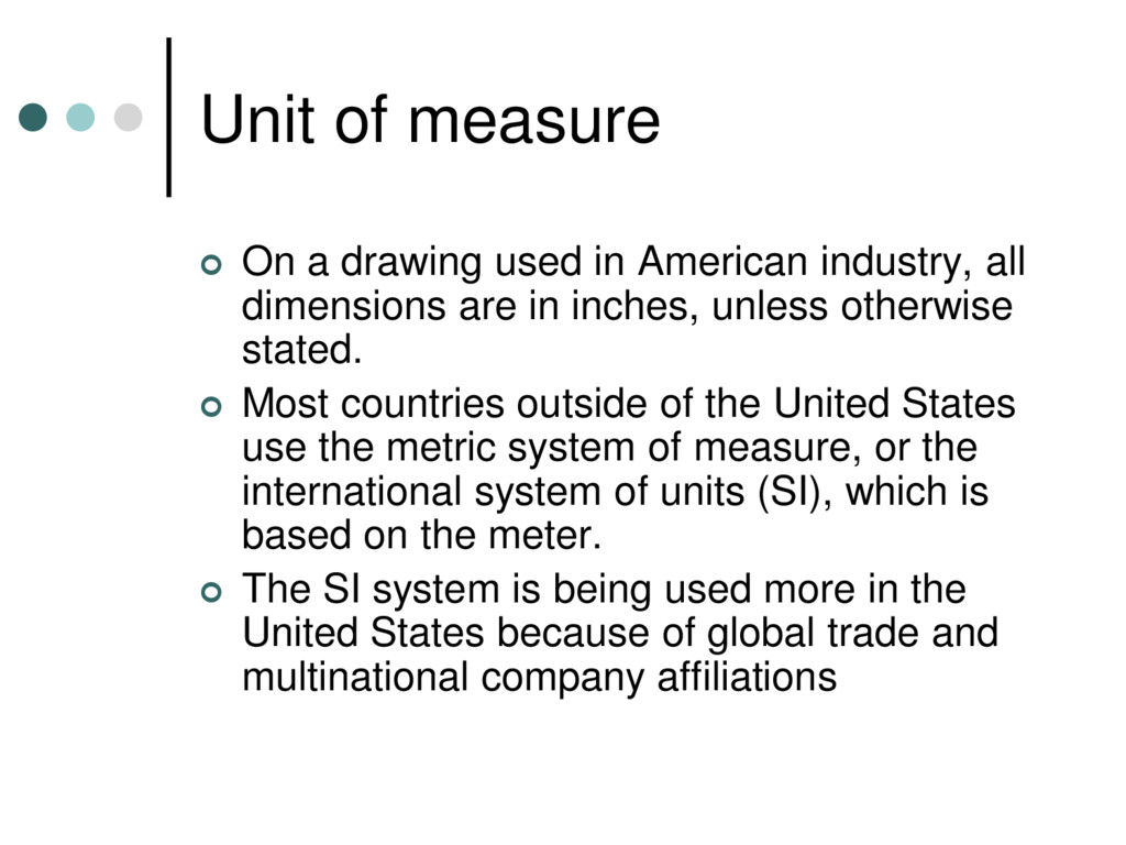
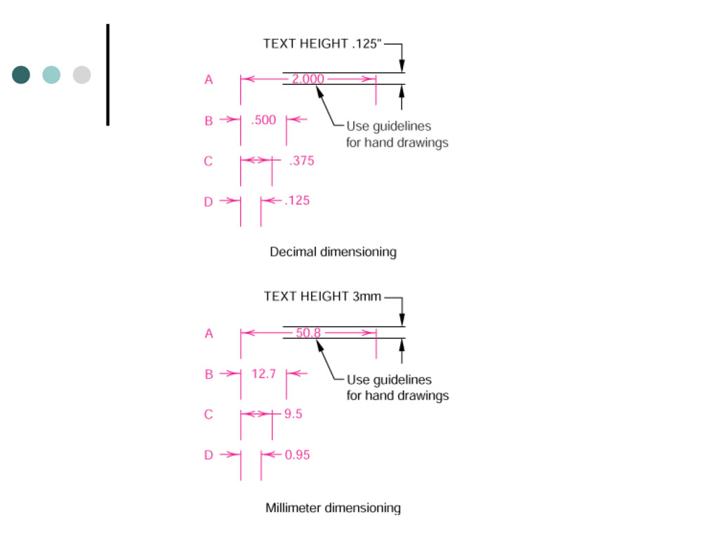
    industry, all dimensions are in inches, unless otherwise stated.  Most countries outside of the United States use the metric system of measure, or the international system of units (SI), which is based on the meter.  The SI system is being used more in the United States because of global trade and multinational company affiliations
  6. Unit of measure  Occasionally, a company will used dual

    dimensioning, that is, both metric and English measurements on a drawing.  Angular dimensions are shown either in decimal degrees or in degrees, minutes, and seconds.
  7. Terminology  Dimension is the numerical value that defines the

    size or geometric characteristic of a feature.  Basic dimension is the numerical value defining the theoretically exact size of a feature.  Reference dimension is the numerical value enclosed in parentheses provided for information only and is not used in the fabrication of the part.
  8. Terminology  Dimension line is the thin solid line which

    shows the extent and direction of a dimension.  Arrows are placed at the ends of dimension lines to show the limits of the dimension.  Extension line is the thin solid line perpendicular to a dimension line indicating which feature is associated with the dimension.
  9. Terminology  Leader line is the thin solid line used

    to indicate the feature with which a dimension, note, or symbol is associated.  Tolerance is the amount a particular dimension is allowed to vary.  Plus and minus dimensioning is the allowable positive and negative variance from the dimension specified.
  10. Terminology  Limits of size is the largest acceptable size

    and the minimum acceptable size of a feature.  The largest acceptable size is expressed as the maximum material condition (MMC)  The smallest acceptable size is expressed as the least material condition (LMC).
  11. Terminology  Diameter symbol is the symbol which is placed

    preceding a numerical value indicating that the associated dimension shows the diameter of a circle. The symbol used is the Greek letter phi.  Radius symbol is the symbol which is placed preceding a numerical value indicating that the associated dimension shows the radius of a circle. The radius symbol used is the capital letter R.
  12. Basic Concepts  Dimensions are used to describe the size

    and location of features on parts for manufacture. The basic criterion is, "What information is necessary to make the object?" Dimensions should not be excessive, either through duplication or dimensioning a feature more than one way.
  13. Basic Concepts  Size dimension might be the overall width

    of the part or the diameter of a drilled hole.  Location dimension might be length from the edge of the object to the center of the drilled hole.
  14. Basic Concepts  Size dimensions  Horizontal  Vertical 

    Diameter  Radius  Location and Orientation  Horizontal  Vertical  Angle
  15. Basic Concepts  Rectangular coordinate dimensioning, a base line (or

    datum line) is established for each coordinate direction, and all dimensions specified with respect to these baselines. This is also known as datum dimensioning, or baseline dimensioning. All dimensions are calculated as X and Y distances from an origin point, usually placed at the lower left corner of the part.
  16. Standard Practices- Placement  Dimension placement depends on the space

    available between extension lines. When space permits, dimensions and arrows are placed between the extension lines.
  17. Standard Practices- Spacing  The minimum distance from the object

    to the first dimension is 10mm (3/8 inch). The minimum spacing between dimensions is 6mm (1/4 inch).  There should be a visible gap between an extension line and the feature to which it refers.  Extension lines should extend about 1mm (1/32 inch) beyond the last dimension line.
  18. Standard Practices- Extension lines  Extension lines are used to

    refer a dimension to a particular feature and are usually drawn perpendicular to the associated dimension line. Where space is limited, extension lines may be drawn at an angle.
  19. Standard Practices- Extension lines  Extension lines should not cross

    dimension lines, and should avoid crossing other extension lines whenever possible.  When extension lines cross object lines or other extension lines, they are not broken.  When extension lines cross or are close to arrowheads, they are broken for the arrowhead.
  20. Standard Practices- Extension lines  When the location of the

    center of a feature is being dimensioned, the center line of the feature is used as an extension line.  When a point is being located by extension lines only, the extensions lines must pass through the point.
  21. Standard Practices- Limited length or areas  When it is

    necessary to define a limited length or area that is to receive additional treatment (such as the knurled portion of a shaft), the extent of the limits may be shown by a chain line. The chain line is drawn parallel to the surface being defined.
  22. Standard Practices- Reading Direction  All dimension and note text

    must be oriented to be read from the bottom of the drawing (relative to the drawing format).  Placement of all text to be read from the bottom of the drawing is called unidirectional dimensioning.  Aligned dimensions have text placed parallel to the dimension line with vertical dimensions read from the right of the drawing sheet.
  23. Standard Practices- View Dimensioning  Dimensions are to be kept

    outside of the boundaries of views of objects wherever practical.  Dimensions may be place within the boundaries of objects in cases where extension or leader lines would be too long, or where clarity would be improved.
  24. Standard Practices- Out-of- Scale Dimensions  If it is necessary

    to include a dimension which is out of scale, the out of scale dimension text must be underlined.
  25. Standard Practices- Repetitive Features  The symbol X is used

    to indicate the number of times a feature is to be repeated. The number of repetitions, followed by the symbol X and a space precedes the dimension text.
  26. Detail Dimensions  Holes  Diameters must be dimensioned with

    the diameter symbol preceding the numerical value.  When holes are dimensioned with a leader line, the line must be radial. A radial line is one that passes through the center of a circle or arc if extended.
  27. Dimension Techniques  Contour Dimensioning  contours or shapes of

    the object are dimensioned in their most descriptive view. For example, the radius of a arc would be dimensioned where it appears as an arc and not as a hidden feature.
  28. Dimension Techniques  Geometric Breakdown  a part is to

    break the part into its geometric configurations.
  29. Dimension Guidelines  The primary guideline is that of clarity

    and whenever two guidelines appear to conflict, the method which most clearly communicates the size information shall prevail.  Every dimension must have an associated tolerance, and that tolerance must be clearly shown on the drawing.  Avoid over-dimensioning a part. Double dimensioning of a feature is not permitted.  Dimensions should be placed in the view which most clearly describes the feature being dimensioned.
  30. Dimension Guidelines  A minimum spacing between the object and

    dimensions and between dimensions must be maintained.  A visible gap shall be placed between the end of extension lines and the feature to which they refer.  Manufacturing methods should not be specified as part of the dimension unless no other method of manufacturing is acceptable.  Placing dimensions within the boundaries of a view should be avoided whenever practicable.
  31. Dimension Guidelines  Dimensions for materials typically manufactured to gages

    or code numbers shall be specified by numerical values.  Unless otherwise specified, angles shown on drawings are assumed to be 90 degrees.  Dimensioning to hidden lines should be avoided whenever possible. Hidden lines are less clear than visible lines.  The depth of blind, counterbored, or countersunk holes may be specified in a note along with the diameter.
  32. Dimension Guidelines  Diameters, radii, squares, counterbores, spotfaces, countersinks, and

    depth should be specified with the appropriate symbol preceding the numerical value.  Leader lines for diameters and radii should be radial lines.
  33. Tolerancing  Tolerance is the total amount a dimension may

    vary and is the difference between the upper (maximum) and lower (minimum) limits.  Tolerances are used to control the amount of variation inherent in all manufactured parts. In particular, tolerances are assigned to mating parts in an assembly.
  34. Tolerancing  One of the great advantages of using tolerances

    is that it allows for interchangeable parts, thus permitting the replacement of individual parts.  Tolerances are used in production drawings to control the manufacturing process more accurately and control the variation between parts.
  35. Tolerancing  Tolerance representation  Direct limits or as tolerance

    values applied directly to a dimension.  Geometric tolerances  Notes referring to specific condition.
  36. Tolerancing  Important terms  Nominal size a dimension used

    to describe the general size usually expressed in common fractions.  Basic size the theoretical size used as a starting point for the application of tolerances.  Actual size the measured size of the finished part after machining.
  37. Tolerancing  Important terms  Limits the maximum and minimum

    sizes shown by the toleranced dimension.  Allowance is the minimum clearance or maximum interference between parts.  Tolerance is the total variance in a dimension which is the difference between the upper and lower limits. The tolerance of the slot in Figure 14.50 is .004" and the tolerance of the mating part is .002".
  38. Tolerancing  Important terms  Maximum material condition (MMC) is

    the condition of a part when it contains the most amount of material. The MMC of an external feature such as a shaft is the upper limit. The MMC of an internal feature such as a hole is the lower limit.
  39. Tolerancing  Important terms  Least material condition (LMC) is

    the condition of a part when it contains the least amount of material possible. The LMC of an external feature is the lower limit of the part. The LMC of an internal feature is the upper limit of the part.
  40. Tolerancing  Fit types  Clearance fit occurs when two

    toleranced mating parts will always leave a space or clearance when assembled.  Interference fit occurs when two toleranced mating parts will always interfere when assembled.  Transition fit occurs when two toleranced mating parts will sometimes be an interference fit and sometimes be a clearance fit when assembled.
  41. Tolerancing  Metric Limits and Fits  Basic size 

    Deviation  Upper Deviation  Lower Deviation  Fundamental Deviation
  42. Tolerancing  Standard Precision Fit; English Units  Running and

    Sliding (RC)  Clearance Locational (LC)  Transition Locational (LT)  Interference Locational (LN)  Force and Shrinks (FN)
  43. Geometric Dimensioning and Tolerancing  GDT is a method of

    defining parts based on how they function, using standard ASME/ANSI symbols.
  44. Geometric Dimensioning and Tolerancing  Within the last 15 years

    there has been considerable interest in GDT, in part because of the increased popularity of statistical process control. This control process, when combined with GDT, helps reduce or eliminate inspection of features on the manufactured object. The flipside is that the part must be toleranced very efficiently; this is where GDT comes in.
  45. Geometric Dimensioning and Tolerancing  Another reason for the increased

    popularity of GDT is the rise of worldwide standards, such as ISO 9000, which require universally understood and accepted methods of documentation.
  46. GDT  Tolerance Calculation  Floating fastener tolerancing is used

    to confirm that loose bolts, screws or other fasteners have the standard clearance in their holes.  Fixed fastener tolerancing is measured the same as with floating fasteners except that the fastener is already fixed/located on one of the mating parts and the tolerance is now divided between the parts.
  47. GDT  Design Application  Five-Step • Isolate and define

    the functions of the features/part. • Prioritize the functions. • Identify the datum reference frame based on functional priorities. • Select the proper control(s). • Calculate the tolerance values.