Upgrade to Pro — share decks privately, control downloads, hide ads and more …

Caterpillar_Cat_980H_Wheel_Loader__Prefix_PF8__...

dcfv
May 20, 2024
8

 Caterpillar_Cat_980H_Wheel_Loader__Prefix_PF8__Service_Repair_Manual__PF800001_and_up_.pdf

dcfv

May 20, 2024
Tweet

More Decks by dcfv

Transcript

  1. Shutdown SIS Previous Screen Product: WHEEL LOADER Model: 980H WHEEL

    LOADER PF8 Configuration: 980H Wheel Loader PF800001-UP (MACHINE) POWERED BY C15 Engine Disassembly and Assembly 980H Wheel Loader Power Train Media Number -UENR3319-00 Publication Date -01/02/2014 Date Updated -04/02/2014 i05584317 Torque Converter - Assemble SMCS - 3101-016 Assembly Procedure Table 1 Required Tools Tool Part Number Part Description Qty A 439-3938 Link Bracket 3 B 8T-5096 Dial Indicator Gp 1 5P-2390 Gauge Tool Gp 1 C 1P-0520 Driver Gp 1 D - Guide Stud 3/8 - 16 by 6 in 2 E - Guide Stud 1/2 - 13 by 6 in 2 NOTICE Keep all parts clean from contaminants. Contaminants may cause rapid wear and shortened component life. Note: Apply oil to all of the bearings before assembly.
  2. Illustration 1 g03543396 1. Use Tooling (C) in order to

    install sleeve bearing (79) in cover assembly (77). Sleeve bearing (79) must be even with the outside surface of cover assembly (77) . Illustration 2 g03543183 2. Install cover assembly (77) to rotating housing (54) . 3. Install ring seal (78) to rotating housing (54) . 4. Install bolts (76) and the washers. Tighten bolts (76) to a torque of 30 ± 5 N·m (22 ± 4 lb ft).
  3. Illustration 3 g03543141 5. Install thrust bearing race (75), thrust

    bearing (74), and thrust bearing race (73) . Illustration 4 g03543037 6. Install retaining ring (72) in turbine hub (69) . Illustration 5 g03543019 7. Install converter turbine (70) on turbine hub (69) .
  4. 8. Install bolts (71) and the washers. Tighten bolts (71)

    to a torque of 50 ± 7 N·m (37 ± 5 lb ft). Illustration 6 g03543017 9. Install turbine hub (69) and converter turbine (70) as a unit to rotating housing (54) . Illustration 7 g03543002 10. Install thrust bearing race (68), thrust bearing (67), and thrust bearing race (66) .
  5. https://www.aservicemanualpdf.com/ My Dear Friend! Thank you very much for visiting.

    Full manual if required, please enter the following URL into your browser. https://www.aservicemanualpdf.com/
  6. Illustration 8 g03545378 11. Use Tooling (C) in order to

    install sleeve bearing (65) to carrier assembly (61). Sleeve bearing (65) must be even with the counterbore of carrier assembly (61) . Illustration 9 g03542979 12. Install retaining ring (64) in stator (63) . Illustration 10 g03542936 13. Raise the temperature of stator (63) . 14. Install stator (63) onto carrier assembly (61) .
  7. Illustration 11 g03542917 15. Install snap ring (62) . Illustration

    12 g03542898 16. Install the stator and carrier assembly (61) as a unit to rotating housing (54) . Illustration 13 g03542876 17. Install thrust bearing race (60), thrust bearing (59), and thrust bearing race (58) .
  8. Illustration 14 g03542857 18. Position impeller hub (57) onto suitable

    cribbing. 19. Install converter impeller (56) on impeller hub (57) . Illustration 15 g03542838 20. Install drive flange (53) on converter impeller (56) .
  9. Illustration 16 g03542819 21. Install bolts (55) to drive flange

    (53). Tighten bolts (55) to a torque of 80 ± 10 N·m (59 ± 7 lb ft). Illustration 17 g03542001 22. Use two people in order to install drive flange (53) on rotating housing (54). The weight of drive flange (53) is approximately 23 kg (51 lb). 23. Install bolts (52) and the washers. Tighten bolts (52) to a torque of 30 ± 5 N·m (22 ± 4 lb ft). Illustration 18 g03545936 24. Lower the temperature of outer bearing race (51) . 25. Install outer bearing race (51) into drive gear (50).
  10. Illustration 19 g03541957 26. Install drive gear (50). Install bolts

    (49) and the washers. Tighten bolts (49) to a torque of 50 ± 7 N·m (37 ± 5 lb ft). Illustration 20 g03546276 27. Raise the temperature of inner bearing (48) . 28. Install inner bearing (48) onto bearing carrier (42) .
  11. Illustration 21 g03541898 29. Install retaining ring (47) onto bearing

    carrier (42) . Illustration 22 g03546297 30. Raise the temperature of ring carrier (46) . 31. Install ring carrier (46) onto bearing carrier (42) . Illustration 23 g03541664 32. Install seal ring (45) onto ring carrier (46) . 33. Install O-ring seal (44) on bearing carrier (42)
  12. Illustration 24 g03541608 34. Install bearing carrier (42) onto torque

    converter (43). Install retaining ring (41) . Illustration 25 g03541164 35. Install studs (40) to torque converter cover (3). Tighten studs (40) to a torque of 100 ± 15 N·m (74 ± 11 lb ft). Illustration 26 g03546363
  13. 36. Install retaining ring (38) into the groove of idler

    gear (28) . Illustration 27 g03546416 37. Lower the temperature of bearing cup (39) . 38. Install bearing cup (39) into idler gear (28) . Illustration 28 g03541116 39. Flip idler gear (28) to the opposite side. Install bearing cup spacer (37) in idler gear (28). The notch in bearing cup spacer (37) must be aligned with the retaining ring.
  14. Illustration 29 g03546456 40. Lower the temperature of bearing cup

    (36) . 41. Install bearing cup (36) into idler gear (28) . Illustration 30 g03540968 42. Install bearing cone (35) , bearing cone spacer (34), and bearing cone (33) in idler gear (28) .
  15. Illustration 31 g03540776 43. Install O-ring seal (32) and ball

    (31) to shaft assembly (29) . Illustration 32 g03546532 44. Install O-ring seal (30) to torque converter cover (3) . 45. Install idler gear (28) and shaft assembly (29) (not show) to torque converter cover (3) . 46. Install bolt (27) and the washer. Tighten bolt (27) to a torque of 120 ± 20 N·m (89 ± 15 lb ft). Illustration 33 g03541363 Improper assembly of parts that are spring loaded can cause bodily injury.
  16. To prevent possible injury, follow the established assembly procedure and

    wear protective equipment. 47. Install poppet (23), spring (24), retainer (25), retaining ring (26), and spacers (22) into spool (21) . Illustration 34 g03541319 48. Install spool (21) and spring (20) into relief valve assembly (16) . Illustration 35 g03541281 Improper assembly of parts that are spring loaded can cause bodily injury. To prevent possible injury, follow the established assembly procedure and wear protective equipment.
  17. 49. Install the O-ring seal, cover (18), and the bolts.

    Repeat this step for the opposite side. 50. Install the O-ring seal and fitting (19) . Illustration 36 g03541236 51. Install O-ring seals (17) to relief valve assembly (16) . Illustration 37 g03541198 52. Position relief valve (16) to torque converter cover (3). Install bolts (15) and the washers.
  18. Illustration 38 g03540719 53. Lower the temperature of bearing cup

    (14) . 54. Install bearing cup (14) to torque converter cover (3) . Illustration 39 g03546602 55. Raise the temperature of bearing cone (13) . 56. Install bearing cone (13) to pump drive gear (12) .
  19. Illustration 40 g03540096 57. Install pump drive gear (12) into

    torque converter cover (3) . Illustration 41 g03540077 58. Lower the temperature of bearing cup (9) . 59. Install bearing cup (9) to pump adapter (8) . 60. Install shims (10) to pump adapter (8) . 61. Apply clean hydraulic oil to O-ring seal (11). Install O-ring seal (9) . Illustration 42 g03546659 62. Install Tooling (D) to torque converter cover (3). Use Tooling (D) in order to guide pump adapter (8) into position on torque converter cover (3) .
  20. Illustration 43 g03546663 63. Install bolts (7) and the washers.

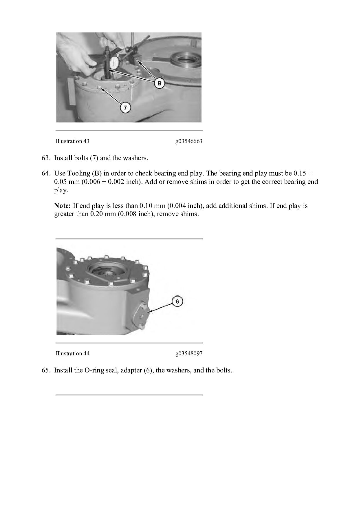
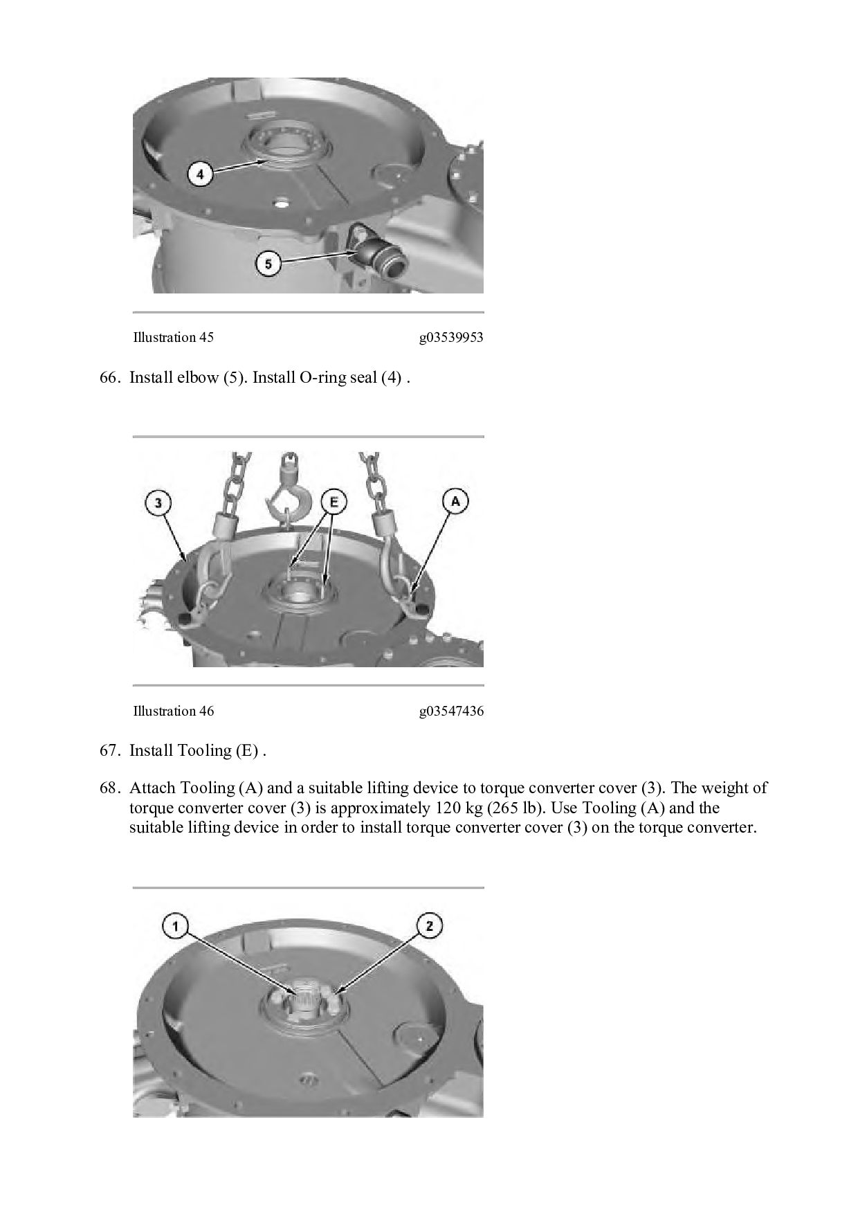
    64. Use Tooling (B) in order to check bearing end play. The bearing end play must be 0.15 ± 0.05 mm (0.006 ± 0.002 inch). Add or remove shims in order to get the correct bearing end play. Note: If end play is less than 0.10 mm (0.004 inch), add additional shims. If end play is greater than 0.20 mm (0.008 inch), remove shims. Illustration 44 g03548097 65. Install the O-ring seal, adapter (6), the washers, and the bolts.
  21. Illustration 45 g03539953 66. Install elbow (5). Install O-ring seal

    (4) . Illustration 46 g03547436 67. Install Tooling (E) . 68. Attach Tooling (A) and a suitable lifting device to torque converter cover (3). The weight of torque converter cover (3) is approximately 120 kg (265 lb). Use Tooling (A) and the suitable lifting device in order to install torque converter cover (3) on the torque converter.
  22. Illustration 47 g03539596 69. Install bolts (2) and the washers.

    Tighten bolts (2) to a torque of 120 ± 20 N·m (89 ± 15 lb ft). Install output shaft (1) . End By: Connect the torque converter to the transmission and the output gears. Copyright 1993 - 2021 Caterpillar Inc. All Rights Reserved. Private Network For SIS Licensees. Sat Mar 20 17:22:08 UTC+0800 2021
  23. Shutdown SIS Previous Screen Product: WHEEL LOADER Model: 980H WHEEL

    LOADER PF8 Configuration: 980H Wheel Loader PF800001-UP (MACHINE) POWERED BY C15 Engine Disassembly and Assembly 980H Wheel Loader Power Train Media Number -UENR3319-00 Publication Date -01/02/2014 Date Updated -04/02/2014 i02187020 Transmission from Output Transfer Gears - Separate SMCS - 3002-076 Separation Procedure Table 1 Required Tools Tool Part Number Part Description Qty A 1U-9200 Lever Puller Hoist 1 B 138-7575 Link Bracket 1 C 138-7575 Link Bracket 3 Start By: a. Separate the torque converter from the transmission. Refer to Disassembly and Assembly, "Torque Converter from Transmission, Output Transfer Gears - Separate".
  24. Illustration 1 g01105945 Illustration 2 g01105953 1. Use Tooling (A),

    Tooling (B) and a suitable lifting device in order to reposition the transmission and output transfer gears (1) onto suitable cribbing. The weight of the transmission and output transfer gears (1) is approximately 1406 kg (3100 lb). Illustration 3 g01105947
  25. 2. Disconnect harness assemblies (2). Illustration 4 g01105969 3. Remove

    bolts (4) and tube assembly (3). Illustration 5 g01105973 4. Remove O-ring seal (5).
  26. Illustration 6 g01105978 5. Attach Tooling (C) and a suitable

    lifting device to transmission (6). The weight of transmission (6) is approximately 726 kg (1600 lb). Remove bolts (7). Do not remove the two smaller bolts (8). Illustration 7 g01105986 6. Use the suitable lifting device in order to remove transmission (6). Copyright 1993 - 2021 Caterpillar Inc. All Rights Reserved. Private Network For SIS Licensees. Sat Mar 20 17:23:05 UTC+0800 2021
  27. Shutdown SIS Previous Screen Product: WHEEL LOADER Model: 980H WHEEL

    LOADER PF8 Configuration: 980H Wheel Loader PF800001-UP (MACHINE) POWERED BY C15 Engine Disassembly and Assembly 980H Wheel Loader Power Train Media Number -UENR3319-00 Publication Date -01/02/2014 Date Updated -04/02/2014 i05593710 Output Transfer Gears - Disassemble SMCS - 3075-015-OJ Disassembly Procedure Table 1 Required Tools Tool Part Number Part Description Qty A 1P-0520 Driver Gp 1 B 8B-7548 Push-Puller Tool Gp 1 8B-7551 Bearing Puller Gp 1 9S-9154 Step Plate 1 C 439-3940 Bracket As 2 D - Forcing Bolt 3/8 - 16 by 6 in 2 Start By: A. Remove the transmission from the output transfer gears. NOTICE Keep all parts clean from contaminants. Contaminants may cause rapid wear and shortened component life.
  28. Illustration 3 g01108605 3. Remove bolt (3) and retainer (4)

    from the input side of the output transfer gear case. Illustration 4 g01108617 4. Remove O-ring seal (5) . Illustration 5 g01108628 5. Remove yoke (6) .
  29. Thank you very much for your reading. Please Click Here.

    Then Get COMPLETE MANUAL. NO WAITING NOTE: If there is no response to click on the link above, please download the PDF document first and then click on it.
  30. Illustration 6 g01108630 6. Remove bolts (7) and the washers

    from bearing cage (8) . Illustration 7 g01108631 7. Use Tooling (D) in order to remove bearing cage (8) . Illustration 8 g01108635
  31. 8. Use Tooling (A) in order to remove lip seal

    (9) and outer bearing race (10) from bearing cage (8) . Illustration 9 g01108639 9. Remove O-ring seal (11) from bearing cage (8) . Illustration 10 g01108665 10. Remove spacer (12) from transfer shaft (13) .
  32. Illustration 11 g01108680 11. Position the transfer case with the

    output side upward, as shown. The weight of the output transfer gear group is 526 kg (1160 lb). 12. Mark bolts (14) for installation purposes. Remove bolts (14) and the washers from bearing cage (15) . 13. Use Tooling (D) in order to loosen bearing cage (15) from the transfer case. Remove bearing cage (15) . Illustration 12 g01108700 14. Position bearing cage (15) onto a suitable press. The combined weight of bearing cage (15) and transfer shaft (13) is approximately 61 kg (135 lb). Use the suitable press in order to press transfer shaft (13) out of bearing cage (15) . Note: Place a suitable block (not shown) under transfer shaft (13) in order to prevent transfer shaft (13) from falling to the ground.
  33. https://www.aservicemanualpdf.com/ My Dear Friend! Thank you very much for visiting.

    Full manual if required, please enter the following URL into your browser. https://www.aservicemanualpdf.com/