Upgrade to Pro — share decks privately, control downloads, hide ads and more …

Caterpillar_Cat_D6M_TRACK-TYPE_TRACTOR__Prefix_...

dcfv
May 21, 2024
5

 Caterpillar_Cat_D6M_TRACK-TYPE_TRACTOR__Prefix_3WN__Service_Repair_Manual__3WN00001_and_up_.pdf

dcfv

May 21, 2024
Tweet

More Decks by dcfv

Transcript

  1. Shutdown SIS Previous Screen Product: TRACK-TYPE TRACTOR Model: D6M TRACK-TYPE

    TRACTOR 3WN Configuration: D6M TRACK-TYPE TRACTOR XL, LGP 3WN00001-UP (MACHINE) POWERED BY 3116 Engine Disassembly and Assembly D6M Track-Type Tractor Power Train Media Number -SENR8387-06 Publication Date -01/11/2010 Date Updated -31/07/2018 i00963856 Bevel and Transfer Gears - Disassemble SMCS - 3011-015 Disassembly Procedure Table 1 Required Tools Tool Part Number Part Description Qty A 5F-7343 Bearing Puller Attachment 1 B 8T-2839 Spanner Wrench 1 C 2P-8312 External Retaining Ring Pliers 1 Start By: a. Separate the transmission and the bevel gears. Refer to Disassembly and Assembly, "Transmission and Bevel Gears - Separate". Note: Cleanliness is an important factor. Before the disassembly procedure, the exterior of the component should be thoroughly cleaned. This will help to prevent dirt from entering the internal mechanism. Dirt and contaminants can damage the components. All disassembly and assembly procedures must be performed on a clean work surface. Clean all the interior components in clean solvent. Dry all the interior components with compressed air. Plug ports and plug hoses on the machine during repair.
  2. Illustration 1 g00742877 1. Remove bracket assemblies (1) and (3)

    from the bevel gear case. Remove the two magnetic sensors (not shown) from bevel gear case. 2. Remove yoke (2). Illustration 2 g00742880 3. Remove four bolts (4). Install two 10 mm forcing screws in the carrier in order to free the carrier (5). Tighten the screws evenly and remove the carrier. 4. Remove O-ring seal (6) from carrier (5). Illustration 3 g00742884
  3. 5. Remove bolts (7). Install two 12 mm forcing screws

    in the cage in order to free the cage (8). Tighten the screws evenly and remove cage (8) and shims (9). Illustration 4 g00742886 6. Remove seal (10) and O-ring seal (11) from cage (8). Illustration 5 g00742885 7. If necessary, remove bearing cup (12) and bearing (13) from cage (8). Illustration 6 g00742887
  4. 8. Remove bolts (14). Remove cover (16). Remove shims (15).

    Illustration 7 g00742888 9. Remove bolts (17). Install two 12 mm forcing screws in the cover in order to free the cover (18). Tighten the screws evenly and remove the cover. Illustration 8 g00742889 10. If necessary, remove dowels (20) and remove bearing cup (19) from cover (18). Illustration 9 g00742890 Note: Gears (22) and (23) must be removed from the case assembly at the same time.
  5. https://www.aservicemanualpdf.com/ My Dear Friend! Thank you very much for visiting.

    Full manual if required, please enter the following URL into your browser. https://www.aservicemanualpdf.com/
  6. 11. Remove gear (22) and gear (23) from the case

    assembly. 12. Remove the bolt and retainer (21) from the gear. Illustration 10 g00742891 13. Use a press and Tooling (A) to remove bearing cone (24) from pinion (25). Illustration 11 g00742892 14. Use a press in order to remove bearing cone (26) and pinion (25) from gears (23). Illustration 12 g00742893
  7. NOTICE Bearing cones (27) and (28) must be destroyed in

    order to remove them from the gear. 15. If necessary, remove bearing cones (27) and (28) from gear (22). Illustration 13 g00742894 16. If necessary, remove bearing cups (29) and (30) from the case assembly. Illustration 14 g00742895 17. Bend the tab on washer (31) away from nut (32). Use Tooling (B) in order to remove the nut from the bevel gear shaft. Remove washer (31) and the washer from the shaft.
  8. Illustration 15 g00742896 18. Slide shaft (33) enough to attach

    a suitable lifting device to the shaft. Fasten a suitable lifting device to shaft (33), and remove the shaft from the case assembly. The weight of the shaft is 39 kg (86.0 lb). Illustration 16 g00742897 19. Use Tooling (C) in order to remove snap ring (35) from shaft (33). Remove bearing (34) from the shaft. Illustration 17 g00742898 20. Remove bolts (36) that hold gear (37) to shaft (33). Remove the gear from the shaft.
  9. Illustration 18 g00742899 21. Remove bolts (38). Remove retainer (41).

    Remove cage (40). Remove shims (39). Illustration 19 g00742900 22. Remove the two bearing cups (43) and bearing cones (42) from cage (40). Copyright 1993 - 2021 Caterpillar Inc. All Rights Reserved. Private Network For SIS Licensees. Thu Dec 16 15:10:17 UTC+0800 2021
  10. Shutdown SIS Previous Screen Product: TRACK-TYPE TRACTOR Model: D6M TRACK-TYPE

    TRACTOR 3WN Configuration: D6M TRACK-TYPE TRACTOR XL, LGP 3WN00001-UP (MACHINE) POWERED BY 3116 Engine Disassembly and Assembly D6M Track-Type Tractor Power Train Media Number -SENR8387-06 Publication Date -01/11/2010 Date Updated -31/07/2018 i00963854 Bevel and Transfer Gears - Assemble SMCS - 3011-016 Assembly Procedure Table 1 Required Tools Tool Part Number Part Description Qty A 2P-8312 Retaining Ring Pliers 1 B 8T-2839 Spanner Wrench 1 C FT1986 Stud 1 2P-8257 Plate 1 6B-6684 Nut 5 2P-8260 Cylinder Liner Installer 1 4B-5273 Washer 3 1D-4719 Nut 2 0S-1590 Bolt 1 D 8S-2328 Dial Indicator Group 1 E 1P-520 Driver Group 1 F FT1986 Stud 1 2P-8257 Plate 1 6B-6684 Nut 8 2P-8260 Cylinder Liner Installer 1
  11. 4B-5273 Washer 4 1D-4719 Nut 2 0S-1590 Bolt 1 1P-1838

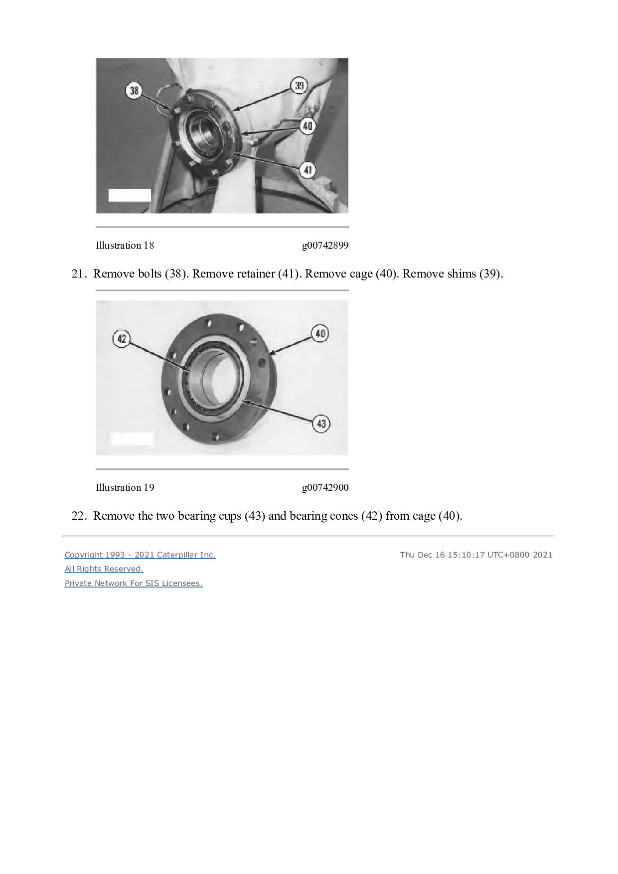
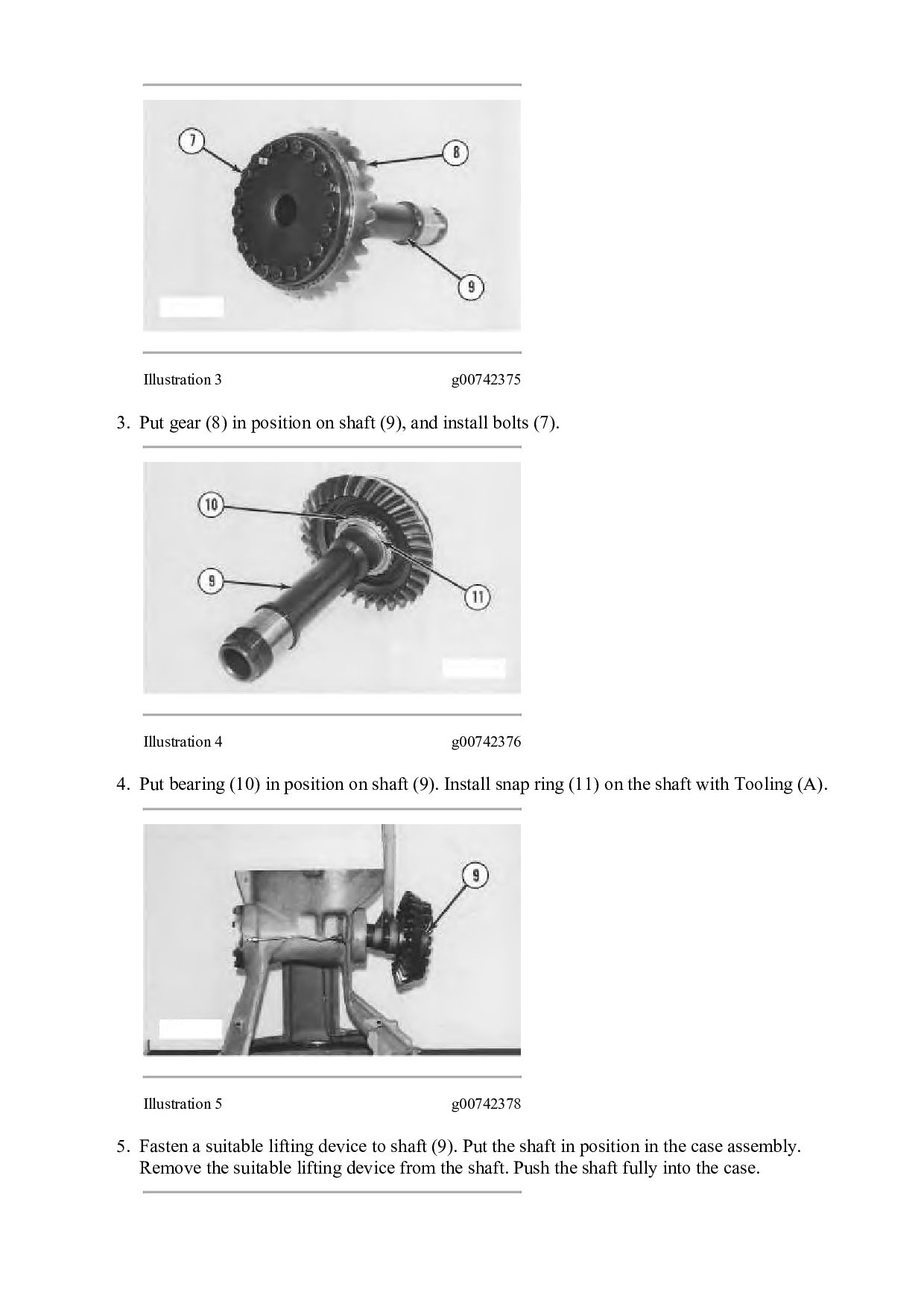
    Adapter 1 1P-1839 Adapter 1 3T-9674 Retainer 1 Note: Cleanliness is an important factor. Before assembly, all parts should be thoroughly cleaned in cleaning fluid. Allow the parts to air dry. Wiping cloths or rags should not be used to dry parts. Lint may be deposited on the parts which may cause later trouble. Inspect all parts. If any parts are worn or damaged, use new parts for replacement. Dirt and other contaminants can damage the components. All disassembly and all assembly procedures must be performed on a clean work surface and in a clean hydraulic area. Keep cleaned parts covered and protected at all times. Illustration 1 g00742082 1. Install bearing cones (1) and bearing cups (2) in cage (3). Illustration 2 g00742374 2. Put the original amount of shims (5), cage (3) and retainer (6) in position on the case assembly, and install bolts (4).
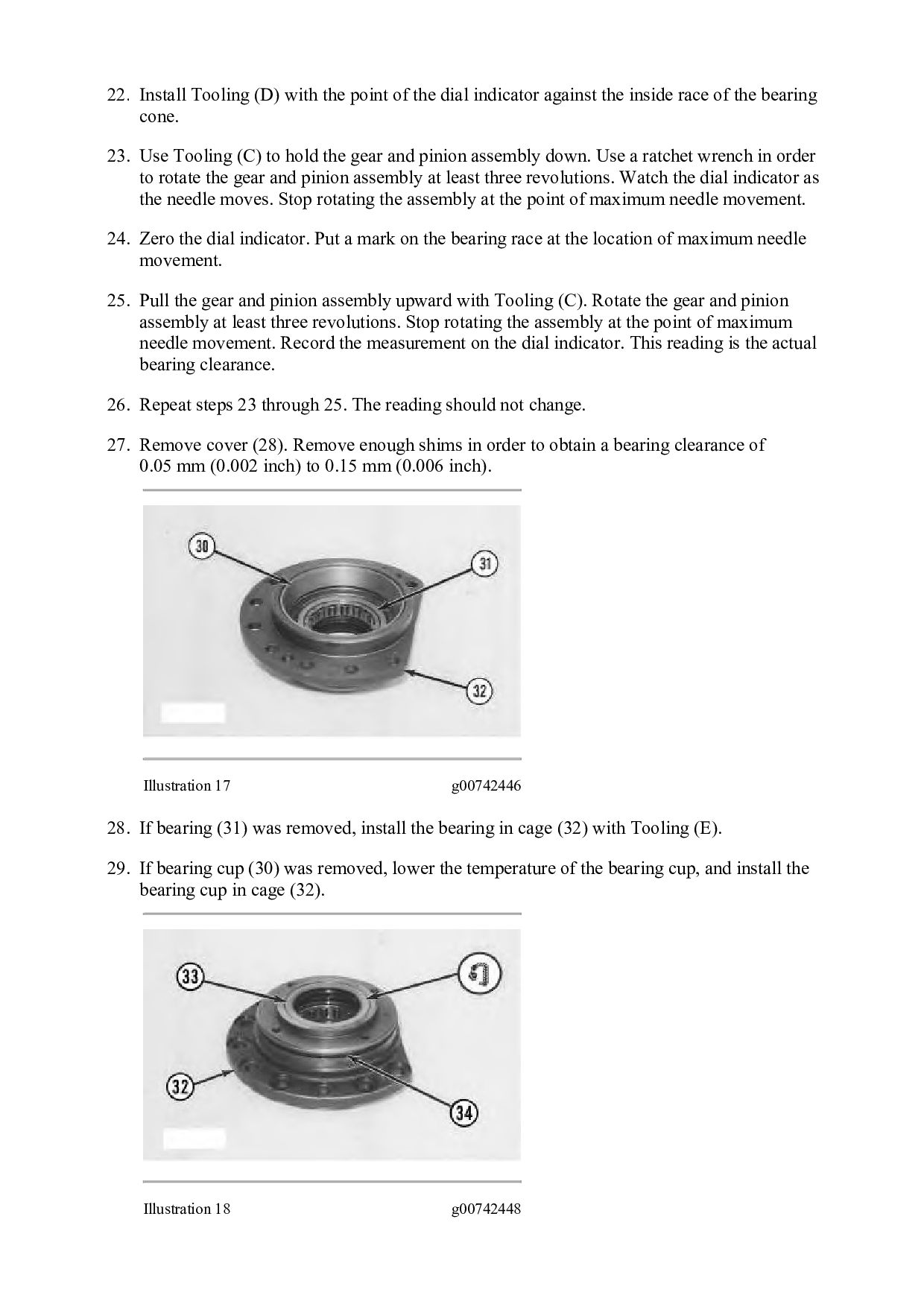
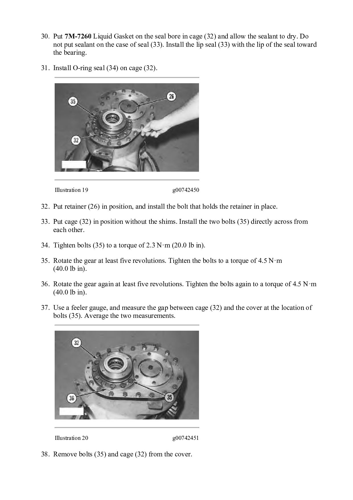
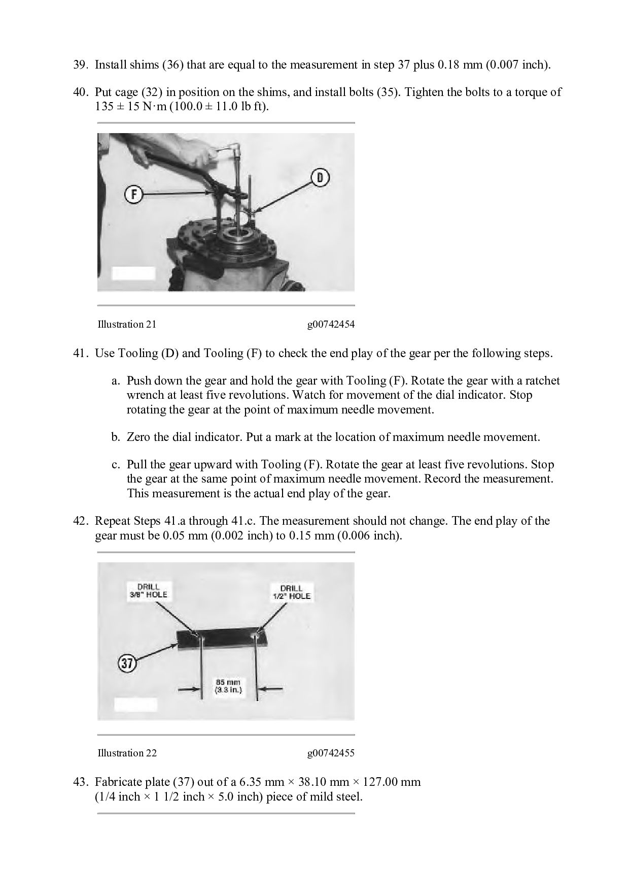
  12. Illustration 3 g00742375 3. Put gear (8) in position on

    shaft (9), and install bolts (7). Illustration 4 g00742376 4. Put bearing (10) in position on shaft (9). Install snap ring (11) on the shaft with Tooling (A). Illustration 5 g00742378 5. Fasten a suitable lifting device to shaft (9). Put the shaft in position in the case assembly. Remove the suitable lifting device from the shaft. Push the shaft fully into the case.
  13. Illustration 6 g00742379 6. Put the washer and washer (12)

    in position on shaft (9). 7. Put 5P-3931 Anti-Seize Compound on the threads and face of nut (13). Install the nut on shaft (9). Use Tooling (B), and tighten the nut to a torque of 612 ± 68 N·m (450.0 ± 50.0 lb ft). Illustration 7 g00742381 8. If bearing cups (14) and (15) were removed, lower the temperature of the bearing cups and install the bearing cups in the case assembly. 9. The bearing cups must be seated in the case assembly.
  14. Illustration 8 g00742382 Note: If the bearing cones were removed

    from gear (18), new bearing cones must be installed. 10. Heat bearing cones (16) and (17) to a maximum temperature of 135°C (275°F). Install the bearing cones on gear (18). The bearing cones must be seated on the gear. Illustration 9 g00742384 11. Put pinion (21) in position in gear (20). 12. Heat bearing cone (19) to a maximum temperature of 135°C (275°F), and install the bearing cone on pinion (21). The bearing cone must be seated on the pinion. 13. Install the retainer and the bolt in order to hold the bearing on the pinion while the bearing cools. Illustration 10 g00742385 14. Heat bearing cone (22) to a maximum temperature of 135°C (275°F), and install the bearing cone on pinion (21). The bearing cone must be seated on the pinion.
  15. Illustration 11 g00742424 Note: Gear (18) and gear (20) must

    be installed in the case assembly at the same time. 15. Install gear (18) and gear (20) in the case assembly. Illustration 12 g00742430 Illustration 13 g00742434 16. If dowels (24) were removed, install the dowel in cover (25). 17. If bearing cup (23) was removed, replace the bearing cup. Dimension (X) should measure 4.37 mm (0.172 inch).
  16. Illustration 14 g00742436 18. Put cover (25) in position, and

    install bolts (27). 19. Remove the bolt and retainer (26). Illustration 15 g00742437 20. Put shims (29) with a total thickness of 4.37 mm (0.172 inch) and cover (28) in position on the cover. Install the bolts that hold the cover in place. Illustration 16 g00742443 21. Install Tooling (C).
  17. 22. Install Tooling (D) with the point of the dial

    indicator against the inside race of the bearing cone. 23. Use Tooling (C) to hold the gear and pinion assembly down. Use a ratchet wrench in order to rotate the gear and pinion assembly at least three revolutions. Watch the dial indicator as the needle moves. Stop rotating the assembly at the point of maximum needle movement. 24. Zero the dial indicator. Put a mark on the bearing race at the location of maximum needle movement. 25. Pull the gear and pinion assembly upward with Tooling (C). Rotate the gear and pinion assembly at least three revolutions. Stop rotating the assembly at the point of maximum needle movement. Record the measurement on the dial indicator. This reading is the actual bearing clearance. 26. Repeat steps 23 through 25. The reading should not change. 27. Remove cover (28). Remove enough shims in order to obtain a bearing clearance of 0.05 mm (0.002 inch) to 0.15 mm (0.006 inch). Illustration 17 g00742446 28. If bearing (31) was removed, install the bearing in cage (32) with Tooling (E). 29. If bearing cup (30) was removed, lower the temperature of the bearing cup, and install the bearing cup in cage (32). Illustration 18 g00742448
  18. 30. Put 7M-7260 Liquid Gasket on the seal bore in

    cage (32) and allow the sealant to dry. Do not put sealant on the case of seal (33). Install the lip seal (33) with the lip of the seal toward the bearing. 31. Install O-ring seal (34) on cage (32). Illustration 19 g00742450 32. Put retainer (26) in position, and install the bolt that holds the retainer in place. 33. Put cage (32) in position without the shims. Install the two bolts (35) directly across from each other. 34. Tighten bolts (35) to a torque of 2.3 N·m (20.0 lb in). 35. Rotate the gear at least five revolutions. Tighten the bolts to a torque of 4.5 N·m (40.0 lb in). 36. Rotate the gear again at least five revolutions. Tighten the bolts again to a torque of 4.5 N·m (40.0 lb in). 37. Use a feeler gauge, and measure the gap between cage (32) and the cover at the location of bolts (35). Average the two measurements. Illustration 20 g00742451 38. Remove bolts (35) and cage (32) from the cover.
  19. 39. Install shims (36) that are equal to the measurement

    in step 37 plus 0.18 mm (0.007 inch). 40. Put cage (32) in position on the shims, and install bolts (35). Tighten the bolts to a torque of 135 ± 15 N·m (100.0 ± 11.0 lb ft). Illustration 21 g00742454 41. Use Tooling (D) and Tooling (F) to check the end play of the gear per the following steps. a. Push down the gear and hold the gear with Tooling (F). Rotate the gear with a ratchet wrench at least five revolutions. Watch for movement of the dial indicator. Stop rotating the gear at the point of maximum needle movement. b. Zero the dial indicator. Put a mark at the location of maximum needle movement. c. Pull the gear upward with Tooling (F). Rotate the gear at least five revolutions. Stop the gear at the same point of maximum needle movement. Record the measurement. This measurement is the actual end play of the gear. 42. Repeat Steps 41.a through 41.c. The measurement should not change. The end play of the gear must be 0.05 mm (0.002 inch) to 0.15 mm (0.006 inch). Illustration 22 g00742455 43. Fabricate plate (37) out of a 6.35 mm × 38.10 mm × 127.00 mm (1/4 inch × 1 1/2 inch × 5.0 inch) piece of mild steel.
  20. Illustration 23 g00742458 44. Install plate (37) in order to

    hold the gear while the backlash is checked. 45. Put Tooling (D) in position with the point of the dial indicator against gear (8). 46. Use Tooling (D) to measure the backlash of gear (8) at three evenly spaced locations. The difference in the three measurements should not be more than 0.08 mm (0.003 inch). Illustration 24 g00742459 47. Add shims or remove shims (38) in order to obtain a backlash of 0.020 mm (0.008 inch) to 0.030 mm (0.012 inch). Remove plate (37) after the backlash has been adjusted. Illustration 25 g00742462
  21. Note: O-rings, gaskets, and seals should always be replaced. A

    used O-ring may not have the same sealing properties as a new O-ring. A reconditioning procedure should not be degraded because of a low cost component such as an O-ring or a gasket. Use 1U-6396 O- Ring Assembly Compound during the assembly procedure. 48. Install O-ring seal (40) on carrier (39). Illustration 26 g00742468 49. Put carrier (39) in position, and install the bolts that hold the carrier in place. 50. Install yoke (41). 51. Install bracket assemblies (42) and (43). 52. Install the two magnetic sensors (not shown) to the bevel gear case. Maintain a 0.89 mm (0.035 inch) gap between the magnetic sensor and the gear tooth. End By: a. Connect the transmission and bevel gears. Refer to Disassembly and Assembly, "Transmission and Bevel Gears - Connect". Copyright 1993 - 2021 Caterpillar Inc. All Rights Reserved. Private Network For SIS Licensees. Thu Dec 16 15:11:13 UTC+0800 2021
  22. Shutdown SIS Previous Screen Product: TRACK-TYPE TRACTOR Model: D6M TRACK-TYPE

    TRACTOR 3WN Configuration: D6M TRACK-TYPE TRACTOR XL, LGP 3WN00001-UP (MACHINE) POWERED BY 3116 Engine Disassembly and Assembly D6M Track-Type Tractor Power Train Media Number -SENR8387-06 Publication Date -01/11/2010 Date Updated -31/07/2018 i04520390 Transmission - Disassemble SMCS - 3030-015 Disassembly Procedure Table 1 Required Tools Tool Part Number Part Description Qty A 1P-2420 Transmission Repair Stand 1 B 138-7573 Link Bracket 2 D 5P-4758 Retaining Ring Pliers As 1 E 8B-7548 Push-Puller Tool Gp 1 6H-1627 Spacer 1 F 1P-1863 Retaining Ring Pliers 1 G 1P-1859 Retaining Ring Pliers 1 L 8H-0663 Bearing Puller Gp 1 Start By: A. Separate the transmission and bevel gears. Refer to Disassembly and Assembly, "Transmission and Bevel Gears-Separate". B. Remove the transmission hydraulic control valves. Refer to Disassembly and Assembly, "Transmission Hydraulic Control Valve-Remove". 1. Place the transmission on Tooling (A) .
  23. Illustration 1 g00716857 2. Install Tooling (B) in housing (1)

    . Fasten a suitable lifting device to Tooling (B) . 3. Support the weight of housing (1) with a suitable lifting device. Use Tooling (A) in order to remove snap ring (2) . 4. Remove bolts (4) and manifold (3) from the planetary group. Illustration 2 g00716853 5. Remove ring (5) and bearing (6) from housing (3) .
  24. Illustration 3 g00716852 6. Remove plates (9) and discs (8)

    . Remove springs (7) . Illustration 4 g00716848 7. Remove piston (10) from the housing assembly. Illustration 5 g00716844 8. Remove ring (108) and (109) from piston (10) .
  25. Illustration 6 g01052455 9. Install Tooling (B) in housing (1)

    . Fasten a suitable lifting device to Tooling (B) . 10. Use Tooling (D) in order to compress ring (12) . Remove housing (1) . Illustration 7 g00716837 11. Remove rings (14) and (15) from the carrier. 12. Remove ring (12) from housing (1) .
  26. Illustration 8 g00716823 13. Use Tooling (E) and a press

    in order to compress the springs in housing (1) . Remove spiral lock ring (16) from coupling (17) . Slowly release the spring tension with the press. Illustration 9 g00716821 14. Remove springs (19) and plate (20) . Remove piston (18) and coupling (17) from housing (1) . 15. Remove rings (21) and (22) from piston (18) .
  27. Illustration 10 g00716797 16. 17. Remove pin (23) and pin

    (25) from carrier (24) . 18. If necessary, break carrier (24) , and remove carrier (24) from housing assembly (1) . Note: On later transmissions, carrier (24) and housing assembly (1) are one piece. Illustration 11 g00716790 19. Remove discs (27) and plates (26) from gear (13) . Illustration 12 g00716780 20. Use Tooling (F) in order to remove snap ring (29) . Remove gear (28) in position on the shaft.
  28. Illustration 13 g00716771 21. Remove gear (13) . Illustration 14

    g00716763 22. Remove ring (31) and plate 30 from gear (13) . Illustration 15 g00716758
  29. Illustration 16 g00716752 23. Remove housing assembly (32) . 24.

    Remove piston (33) from housing assembly (32) . 25. Remove springs (35) and rods (54) . 26. Remove discs (36) and plates (34) . Illustration 17 g00716749 27. Remove rings (106) and (107) from piston (33) .
  30. Illustration 18 g00716748 28. Remove the carrier from gear (38)

    . Illustration 19 g00716747 29. Remove ring (40) . 30. Remove ring (41) . 31. Remove pin (44) . 32. Remove shafts (42) . Remove gears (45) and discs (43) from carrier (37) . 33. Remove the bearings from gears (45) .
  31. Illustration 20 g00716745 34. Remove snap ring (46) that holds

    the bearing in carrier (47) . Illustration 21 g00716743 35. Remove shaft (48) . Illustration 22 g00716741 36. Use Tooling (F) in order to remove snap ring (49) . Remove gear (50) from the shaft.
  32. 37. Remove the bearing (51) . Remove the dowel from

    shaft (48) . Illustration 23 g00716738 Illustration 24 g00716739 38. Remove bearing (104) , and bearing (105) . Illustration 25 g00716737
  33. 39. Remove bolts (53) that hold housing (52) in place.

    Illustration 26 g00716734 40. Remove housing (52) . 41. Remove piston (55) from housing (52) . 42. Remove discs (57) and plates (58) . Illustration 27 g00716731 43. Remove rings (102) and (103) from piston (55) .
  34. Thank you very much for your reading. Please Click Here.

    Then Get COMPLETE MANUAL. NO WAITING NOTE: If there is no response to click on the link above, please download the PDF document first and then click on it.
  35. Illustration 28 g00716729 44. Remove gear (60) . 45. Remove

    plates (59) . Illustration 29 g00716385 46. Remove plates (62) and discs (61) . Illustration 30 g00716382
  36. 47. Use Tooling (G) in order to remove snap ring

    (63) . Illustration 31 g00716379 48. Remove carrier (47) and gear (64) . 49. Compress the ring in carrier (47) . Remove carrier (47) from gear (64) . 50. Remove the thrust disc from carrier (47) . Illustration 32 g00716377
  37. Illustration 33 g00716375 51. Remove ring (65) from carrier (47)

    . 52. Remove pin (66) from carrier (47) . 53. Remove shafts (67) . Remove gear (69) , gear (74) , and discs (68) , (71) , (72) and (75) from carrier (47) . 54. Install bearing (70) and bearing (73) in gears (69) and (74) . Illustration 34 g00716373 55. Use Tooling (G) in order to expand ring (76) . Remove gear (78) and bearing (77) from carrier (47) .
  38. https://www.aservicemanualpdf.com/ My Dear Friend! Thank you very much for visiting.

    Full manual if required, please enter the following URL into your browser. https://www.aservicemanualpdf.com/