Upgrade to Pro — share decks privately, control downloads, hide ads and more …

Caterpillar_Cat_D6N_XL_TRACK-TYPE_TRACTOR__Pref...

dcrfqdcnvk
May 21, 2024
8

 Caterpillar_Cat_D6N_XL_TRACK-TYPE_TRACTOR__Prefix_PER__Service_Repair_Manual__PER00001_and_up_.pdf

dcrfqdcnvk

May 21, 2024
Tweet

More Decks by dcrfqdcnvk

Transcript

  1. Shutdown SIS Previous Screen Product: TRACK-TYPE TRACTOR Model: D6N XL

    TRACK-TYPE TRACTOR PER Configuration: D6N TRACK-TYPE TRACTOR XL, LGP PER00001-UP (MACHINE) POWERED BY C6.6 Engine Disassembly and Assembly D6N Track-Type Tractor Power Train Media Number -UENR0055-02 Publication Date -01/01/2012 Date Updated -13/12/2016 i04390445 Bevel and Transfer Gears - Disassemble SMCS - 3011-015 Disassembly Procedure Table 1 Required Tools Tool Part Number Part Description Qty A 1P-2420 Transmission Repair Stand 1 B 5F-7343 Bearing Puller Gp 1 C 8T-2839 Spanner Wrench 1 Start By: a. Separate the transmission and bevel gears. Illustration 1 g02560901
  2. 1. Mount bevel and transfer gears (1) onto Tooling (A).

    Illustration 2 g02561261 2. Remove O-ring seals (3). 3. If necessary, remove pins (2). Illustration 3 g02561677 4. Remove guard (4), if installed, sensors (5), and bracket (6).
  3. Illustration 4 g02561822 5. Remove pulley (7). Remove cage (9)

    and shims (10). Note: Use two bolts (8) in order to remove cage (9). Illustration 5 g00994151 6. Remove O-ring seal (12), seal (11), bearing cone (14), and bearing cup (13) from cage (9).
  4. Illustration 6 g02561957 7. Remove bolts (15), cover (16), and

    shims (17). 8. Remove tube (17A). Illustration 7 g00954587 9. Remove bolts (18). Use two bolts (18) in order to remove cover (19). Tighten bolts (18) evenly and remove cover (19). Illustration 8 g00994154 10. If necessary, remove dowels (20) and bearing cup (21) from cover (19).
  5. https://www.aservicemanualpdf.com/ My Dear Friend! Thank you very much for visiting.

    Full manual if required, please enter the following URL into your browser. https://www.aservicemanualpdf.com/
  6. Illustration 9 g00954590 11. Remove gear (22) and gear (23)

    from the case assembly. Illustration 10 g00954593 Note: Bearing cones (24) must be destroyed in order to remove the cones from the gear. 12. Remove bearing cones (24) from gear (22).
  7. Illustration 11 g00994158 13. Remove bolt (25) and retainer (26)

    from gear (23). Illustration 12 g00954591 14. Use Tooling (B) and a suitable press in order to remove bearing cone (27) from gear (28).
  8. Illustration 13 g00994331 15. Use a suitable press in order

    to remove bearing cone (29) from gear (28) and from gear (23). Illustration 14 g00954857 16. Remove bearing cups (30) from case (31).
  9. Illustration 15 g00994147 17. Bend the tab on lock ring

    (33) away from nut (32). Note: Use a new lock ring (33) during assembly. 18. Use Tooling (C) in order to remove nut (32). 19. Remove washer (34) and bearing cone (34A).
  10. Illustration 16 g01233575 20. Attach a suitable lifting device to

    shaft assembly (35). The weight of shaft assembly (35) is approximately 39 kg (86 lb). 21. Remove shaft assembly (35). Illustration 17 g00954861 22. Remove bolts (36) and gear (37). Illustration 18 g00954863 23. Remove race and roller bearing (38) from shaft assembly (35).
  11. Illustration 19 g00994148 24. Remove bolts (39), cage (40), and

    shims (41). Illustration 20 g00994149 25. Remove bearing cone (46), bearing cups (45) and (42), and carrier (44). 26. Remove rings (43) from carrier (44).
  12. Illustration 21 g00994563 27. Remove bearing cup (47) from case

    (31). Illustration 22 g00994564 28. Remove tube assemblies (49). Remove fittings (48), if necessary. Copyright 1993 - 2021 Caterpillar Inc. All Rights Reserved. Private Network For SIS Licensees. Mon Nov 29 11:36:34 UTC+0800 2021
  13. Shutdown SIS Previous Screen Product: TRACK-TYPE TRACTOR Model: D6N XL

    TRACK-TYPE TRACTOR PER Configuration: D6N TRACK-TYPE TRACTOR XL, LGP PER00001-UP (MACHINE) POWERED BY C6.6 Engine Disassembly and Assembly D6N Track-Type Tractor Power Train Media Number -UENR0055-02 Publication Date -01/01/2012 Date Updated -13/12/2016 i04670350 Bevel and Transfer Gears - Disassemble SMCS - 3011-015 Disassembly Procedure Table 1 Required Tools Tool Part Number Part Description Qty A 1P-2420 Transmission Repair Stand 1 B 5F-7343 Bearing Puller Gp 1 C 8T-2839 Spanner Wrench 1 Start By: a. Separate the transmission and bevel gears. Refer to Disassembly and Assembly, "Transmission and Bevel Gears - Separate".
  14. Illustration 1 g00959670 1. Mount bevel and transfer gears (1)

    onto Tooling (A). Illustration 2 g00954579 2. Remove bracket assemblies (2).
  15. Illustration 3 g00954580 3. Remove O-ring seals (4). 4. If

    necessary, remove pins (3). Illustration 4 g01228572 5. Disconnect harness assemblies (7), sensors (5), and bracket (6).
  16. Illustration 5 g00954584 6. Remove bolts (8). Use two bolts

    (8) in order to remove cage (9). 7. Remove shims (10). Illustration 6 g00994151 8. Remove O-ring seal (12), seal (11), bearing (14), and bearing cup (13) from cage (9).
  17. Illustration 7 g00994324 9. Remove bolts (15), cover (16), and

    shims (17). Illustration 8 g00954587 10. Remove bolts (18). Use two bolts (18) in order to remove cover (19). Tighten bolts (18) evenly and remove cover (19).
  18. Illustration 9 g00994154 11. If necessary, remove dowels (20) and

    bearing cup (21) from cover (19). Illustration 10 g00954590 Note: Gears (22) and (23) must be removed from the case assembly at the same time. 12. Remove gear (22) and gear (23) from the case assembly.
  19. Illustration 11 g00954593 Note: Bearing cones (24) must be destroyed

    in order to remove the cones from the gear. 13. Remove bearing cones (24) from gear (22). Illustration 12 g00994158 14. Remove bolt (25) and retainer (26) from gear (23).
  20. Illustration 13 g00954591 15. Use Tooling (B) and a suitable

    press in order to remove bearing cone (27) from gear (28). Illustration 14 g00994331 16. Use a suitable press in order to remove bearing cone (29) from gear (28) and from gear (23).
  21. Illustration 15 g00954857 17. Remove bearing cups (30) from case

    (31). Illustration 16 g00994147 18. Bend the tab on lock ring (33) away from nut (32).
  22. Note: Use a new lock ring (33) during assembly. 19.

    Use Tooling (C) in order to remove nut (32). 20. Remove washer (34) and bearing cone (34A). Illustration 17 g01233575 21. Attach a suitable lifting device to shaft assembly (35). The weight of shaft assembly (35) is approximately 39 kg (86 lb). 22. Remove shaft assembly (35). Illustration 18 g00954861 23. Remove bolts (36) and gear (37).
  23. Illustration 19 g00954863 24. Remove the race and roller bearing

    (38) from shaft assembly (35). Illustration 20 g00994148 25. Remove bolts (39), cage (40), and shims (41).
  24. Illustration 21 g00994149 26. Remove bearing cone (46), bearing cups

    (45) and (42), and carrier (44). 27. Remove rings (43) from carrier (44). Illustration 22 g00994563 28. Remove bearing cup (47) from case (31).
  25. Illustration 23 g00994564 29. Remove tube assemblies (49). Remove fittings

    (48), if necessary. Copyright 1993 - 2021 Caterpillar Inc. All Rights Reserved. Private Network For SIS Licensees. Mon Nov 29 11:37:30 UTC+0800 2021
  26. Shutdown SIS Previous Screen Product: TRACK-TYPE TRACTOR Model: D6N XL

    TRACK-TYPE TRACTOR PER Configuration: D6N TRACK-TYPE TRACTOR XL, LGP PER00001-UP (MACHINE) POWERED BY C6.6 Engine Disassembly and Assembly D6N Track-Type Tractor Power Train Media Number -UENR0055-02 Publication Date -01/01/2012 Date Updated -13/12/2016 i04670352 Bevel and Transfer Gears - Assemble SMCS - 3011-016 Assembly Procedure Table 1 Required Tools Tool Part Number Part Description Qty A 1P-2420 Transmission Repair Stand 1 C 8T-2839 Spanner Wrench 1 E 8T-5096 Dial Indicator Gp 1 6V-6042 Indicator Point Gp 1 F 8T-4122 Hard Washer 1 8B-7558 Adapter 1 1B-3623 Bolt 1 2P-8260 Cylinder Liner Installer 1 G 2P-8260 Cylinder Liner Installer 1 9U-6207 Plate 1 031-9099 Bolt 1 2J-3506 Full Nut 1 8T-4994 Hard Washer 1 H 4C-5597 Anti-Seize Compound J 1U-7234 Feeler Gauge 1
  27. K 1P-0510 Driver Gp 1 L FT-2973 Holding Plate 1

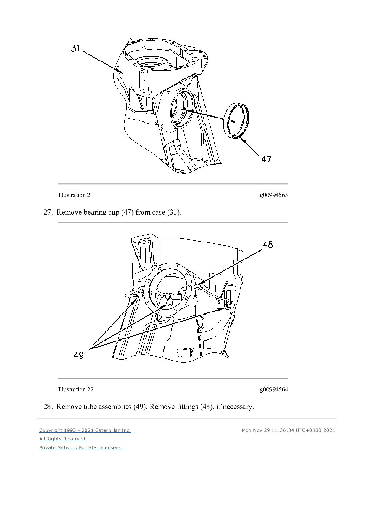
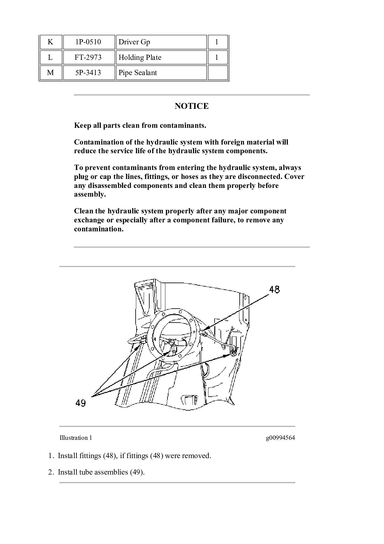
    M 5P-3413 Pipe Sealant NOTICE Keep all parts clean from contaminants. Contamination of the hydraulic system with foreign material will reduce the service life of the hydraulic system components. To prevent contaminants from entering the hydraulic system, always plug or cap the lines, fittings, or hoses as they are disconnected. Cover any disassembled components and clean them properly before assembly. Clean the hydraulic system properly after any major component exchange or especially after a component failure, to remove any contamination. Illustration 1 g00994564 1. Install fittings (48), if fittings (48) were removed. 2. Install tube assemblies (49).
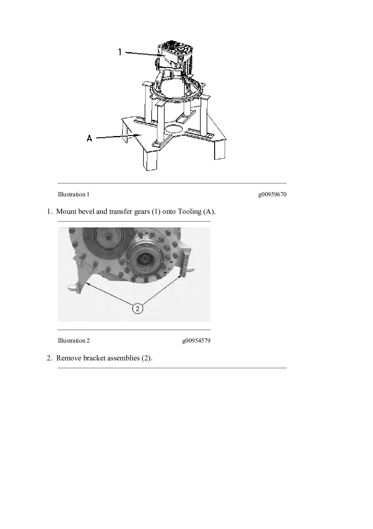
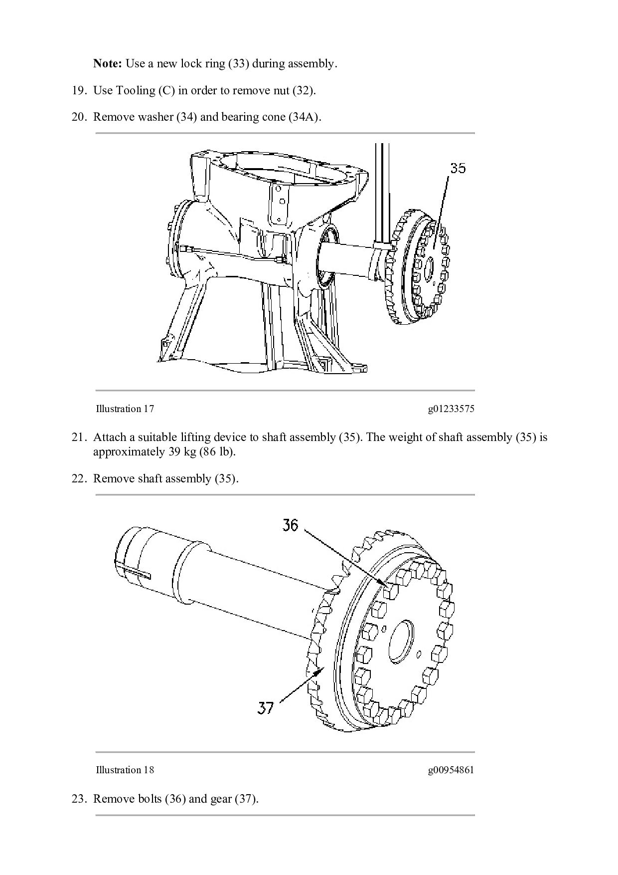
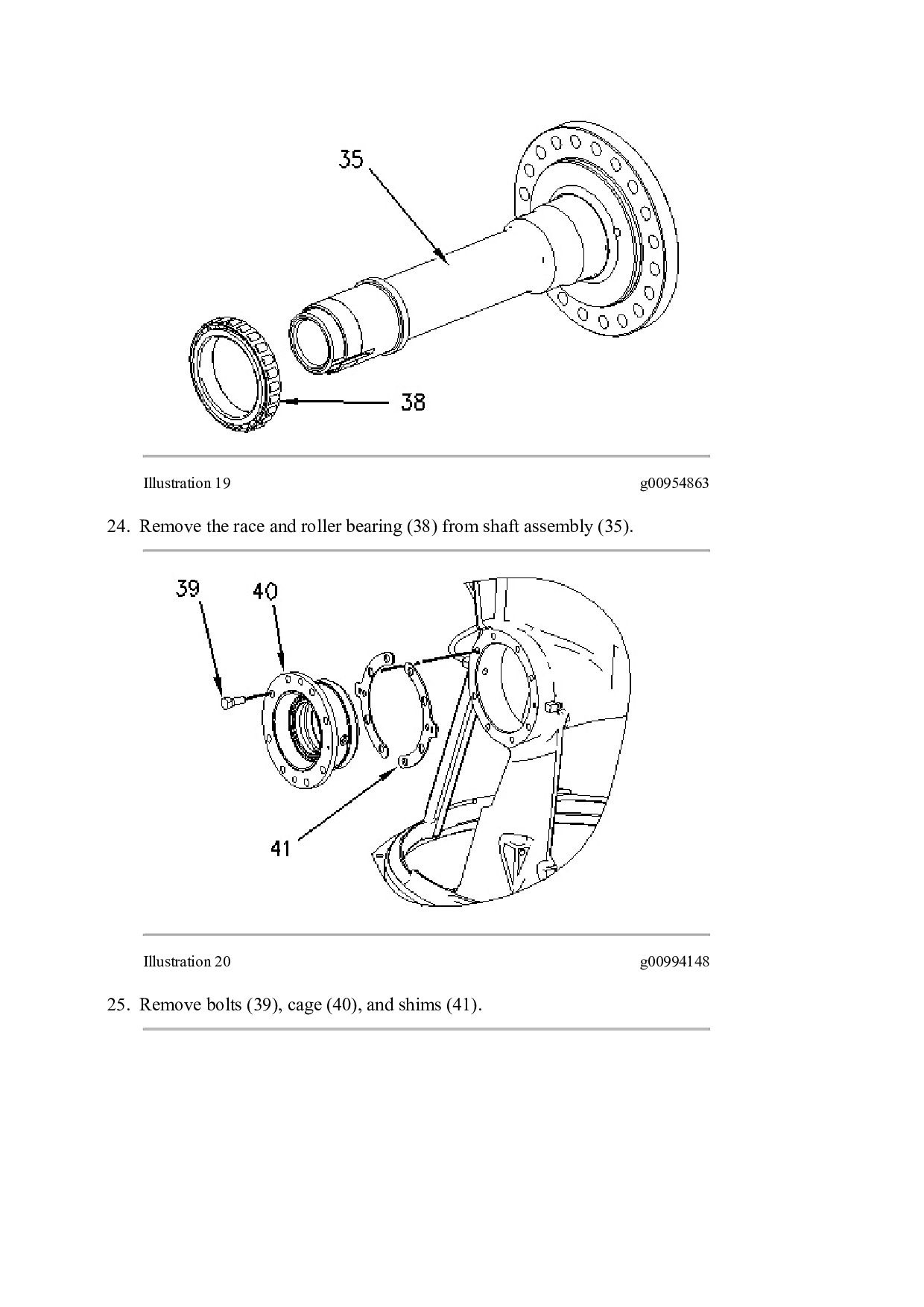
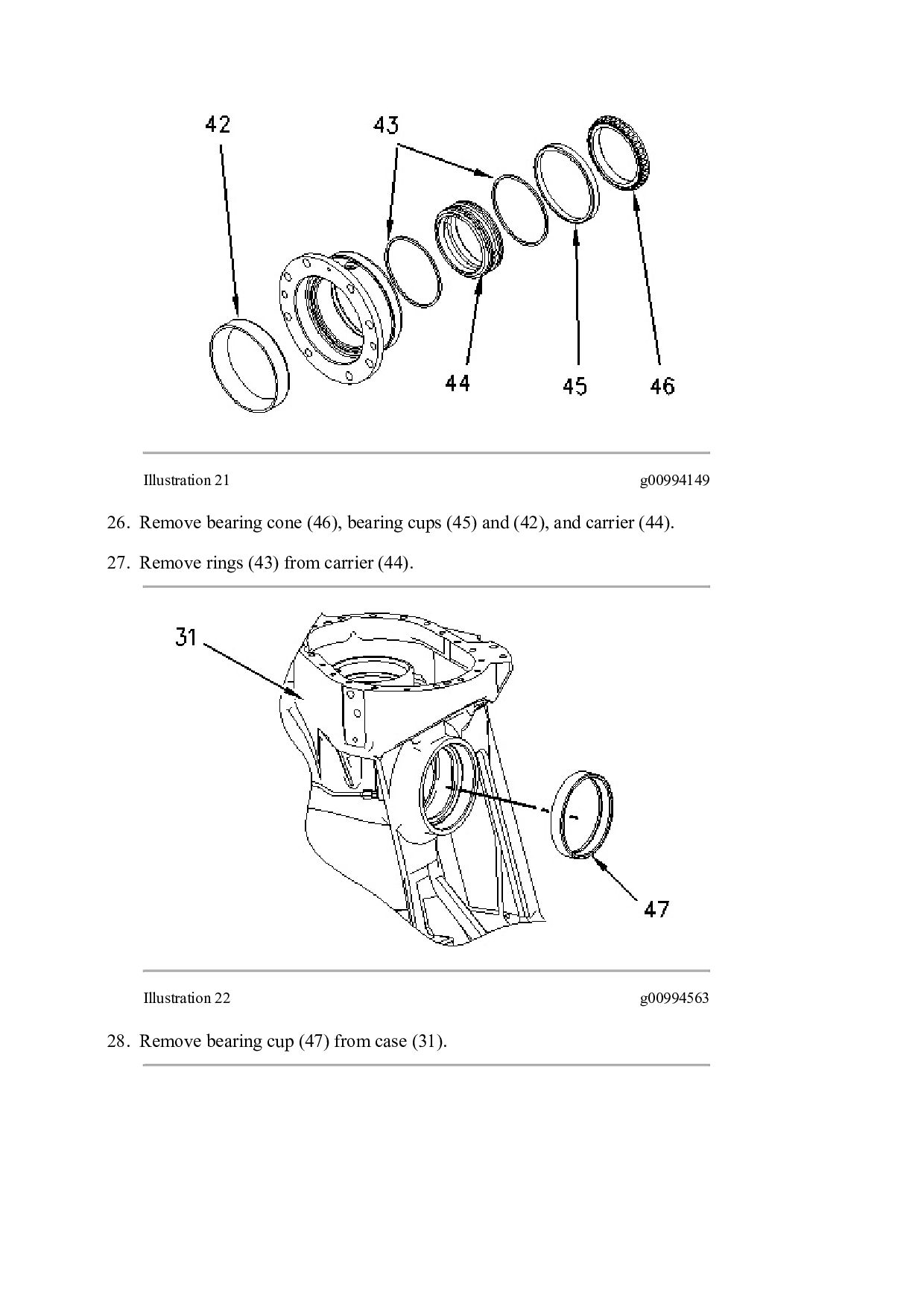
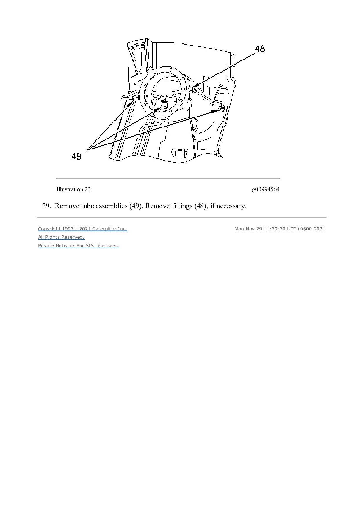
  28. Illustration 2 g00994563 3. Lower the temperature of bearing cup

    (47). 4. Install bearing cup (47) into case (31). Illustration 3 g00994149 5. Install rings (43) into carrier (44). 6. Install carrier (44). 7. Lower the temperature of bearing cups (42) and (45). Install bearing cups (42) and (45). 8. Install bearing cone (46).
  29. Illustration 4 g00994148 9. Install original shims (41), cage (40),

    and bolts (39). Illustration 5 g00954863 10. Raise the temperature of race and roller bearing (38). 11. Install the race and roller bearing (38) onto shaft assembly (35).
  30. Illustration 6 g00954861 12. Position gear (37). Install bolts (36).

    Illustration 7 g01233575 13. Attach a suitable lifting device to shaft assembly (35). The weight of shaft assembly (35) is approximately 39 kg (86 lb). 14. Install shaft assembly (35).
  31. Illustration 8 g00994147 15. Install bearing cone (34A), washer (34),

    and new lock ring (33). 16. Apply Tooling (H) to the threads and to the face of nut (32). Install nut (32). 17. Use Tooling (C) in order to tighten nut (32) to a torque of 612 ± 68 N·m (451 ± 50 lb ft). 18. Bend the tab on lock ring (33) toward nut (32).
  32. Illustration 9 g00954857 19. Lower the temperature of bearing cups

    (30). 20. Install bearing cups (30) into case (31). Illustration 10 g00971426 21. Raise the temperature of bearing cones (27) and (29). 22. Install bearing cone (27) onto gear (28). 23. Install gear (28) into gear (23). 24. Install bearing cone (29) onto gear (28). 25. Position retainer (26). 26. Install bolt (25).
  33. Illustration 11 g00954593 27. Raise the temperature of bearing cones

    (24). Install bearing cones (24) onto gear (22). Illustration 12 g00954590 Note: Gears (22) and (23) must be installed into the case assembly at the same time. 28. Install gear (22) and gear (23) into the case assembly.
  34. Thank you very much for your reading. Please Click Here.

    Then Get COMPLETE MANUAL. NO WAITING NOTE: If there is no response to click on the link above, please download the PDF document first and then click on it.
  35. Thank you very much for your reading. Please Click Here.

    Then Get COMPLETE MANUAL. NO WAITING NOTE: If there is no response to click on the link above, please download the PDF document first and then click on it.
  36. Illustration 13 g00984442 29. Install bearing cup (21) into cover

    (19). Dimension (Z) is 4.30 mm (0.170 inch). Illustration 14 g00984467 30. Position cover (19). 31. Install dowels (20), if dowels (20) were removed. Install bolts (18). 32. Install bolt (25) and retainer (26).
  37. Illustration 15 g00994324 33. Position shim (17) that is equal

    to 4.30 mm (0.169 inch) onto cover (19). 34. Install cover (16) and bolts (15). Illustration 16 g00984480 35. Install Tooling (E) and Tooling (F). 36. Rotate gear (28) in order to find the high spot on the face of bearing cone (29). 37. Zero Tooling (E). 38. Obtain an end play measurement.
  38. 39. Repeat Step 36 through Step 38 in order to

    ensure that an accurate measurement has been obtained. 40. Remove Tooling (E) and Tooling (F). Illustration 17 g00994324 41. Remove bolts (15) and cover (16). 42. Remove shims (17) in order to adjust the end play. The end play should be 0.080 ± 0.050 mm (0.0031 ± 0.0020 inch). 43. Install cover (16) and bolts (15). 44. Repeat Step 35 through Step 43 in order to ensure that an accurate measurement has been obtained.
  39. https://www.aservicemanualpdf.com/ My Dear Friend! Thank you very much for visiting.

    Full manual if required, please enter the following URL into your browser. https://www.aservicemanualpdf.com/