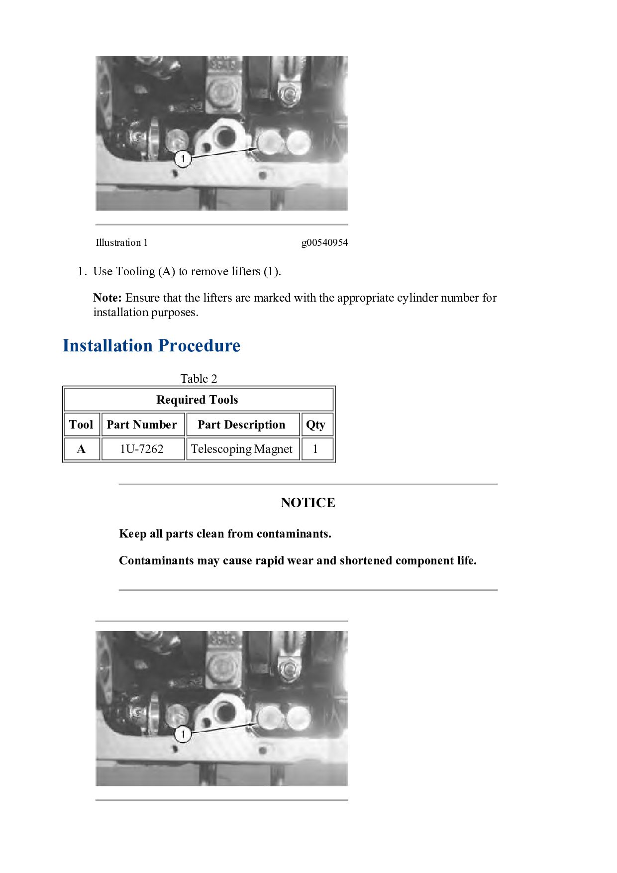
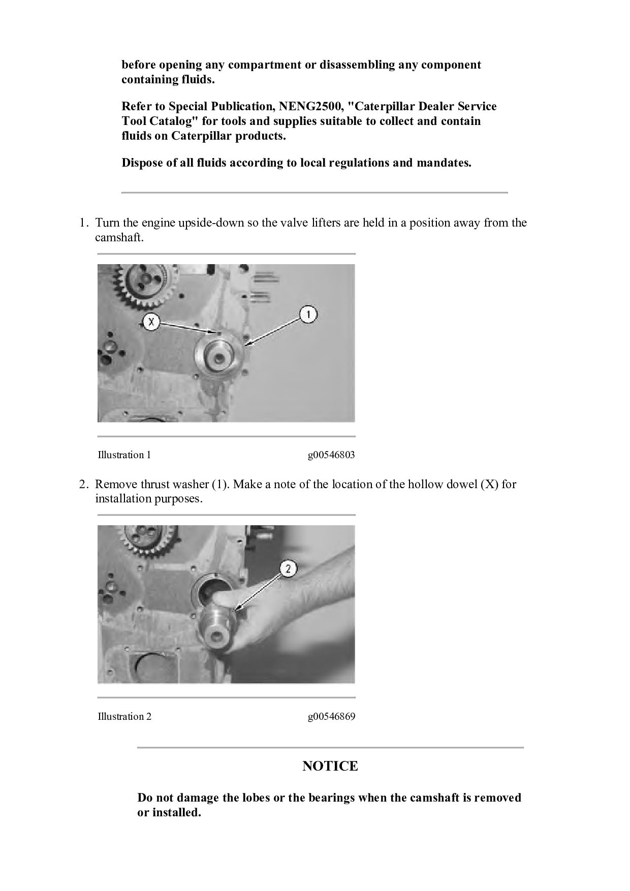
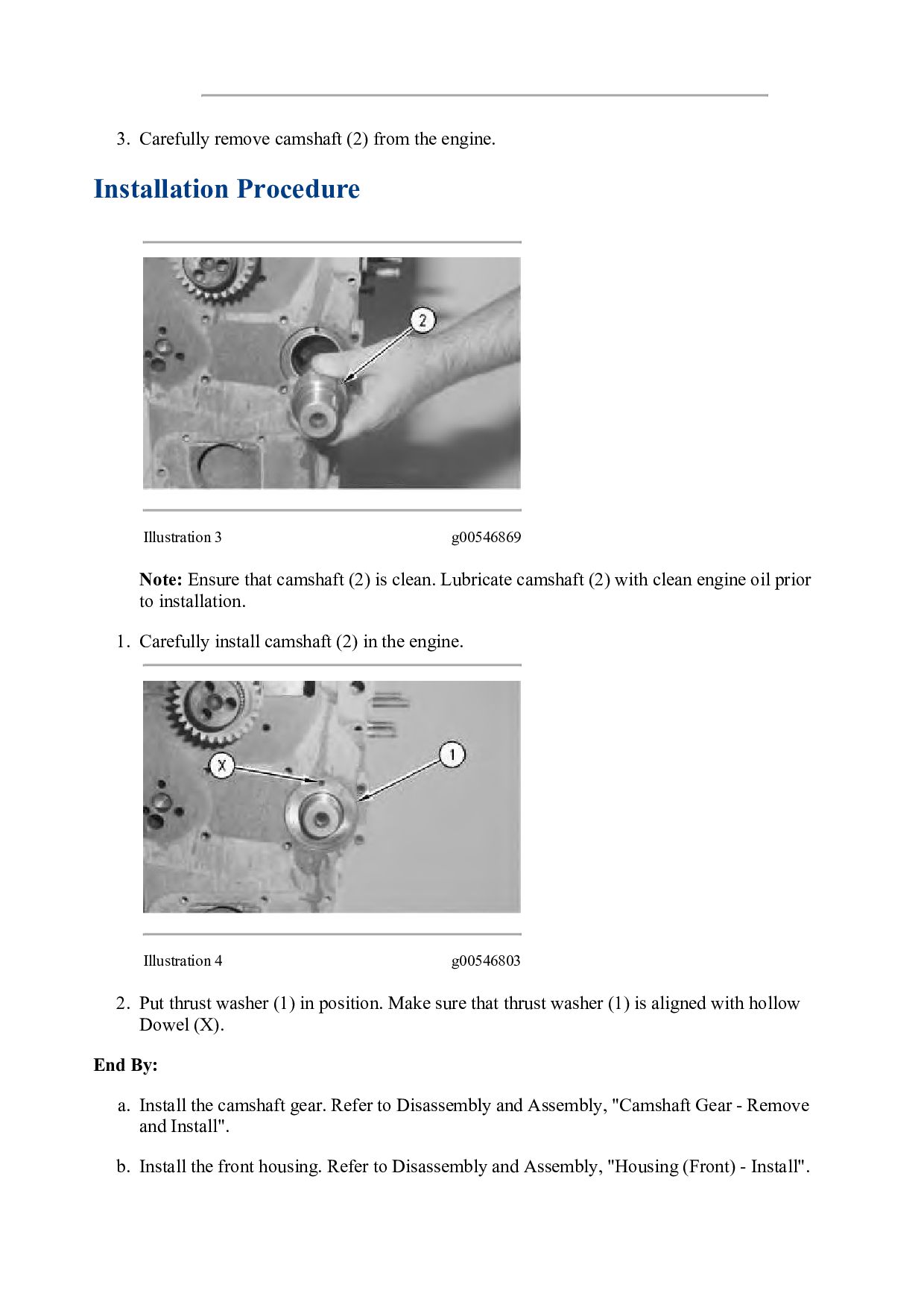
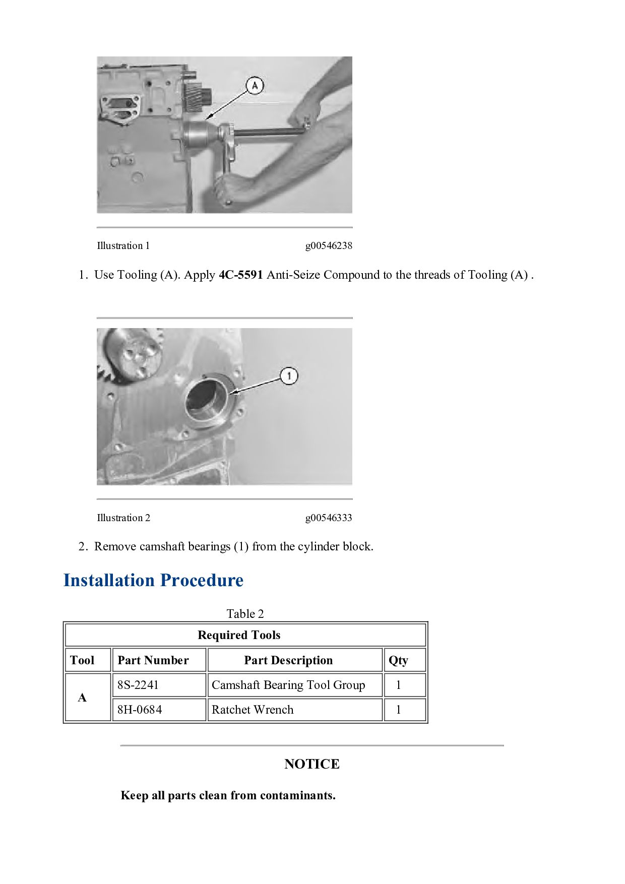
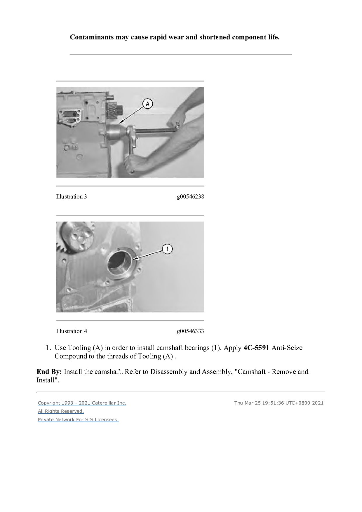
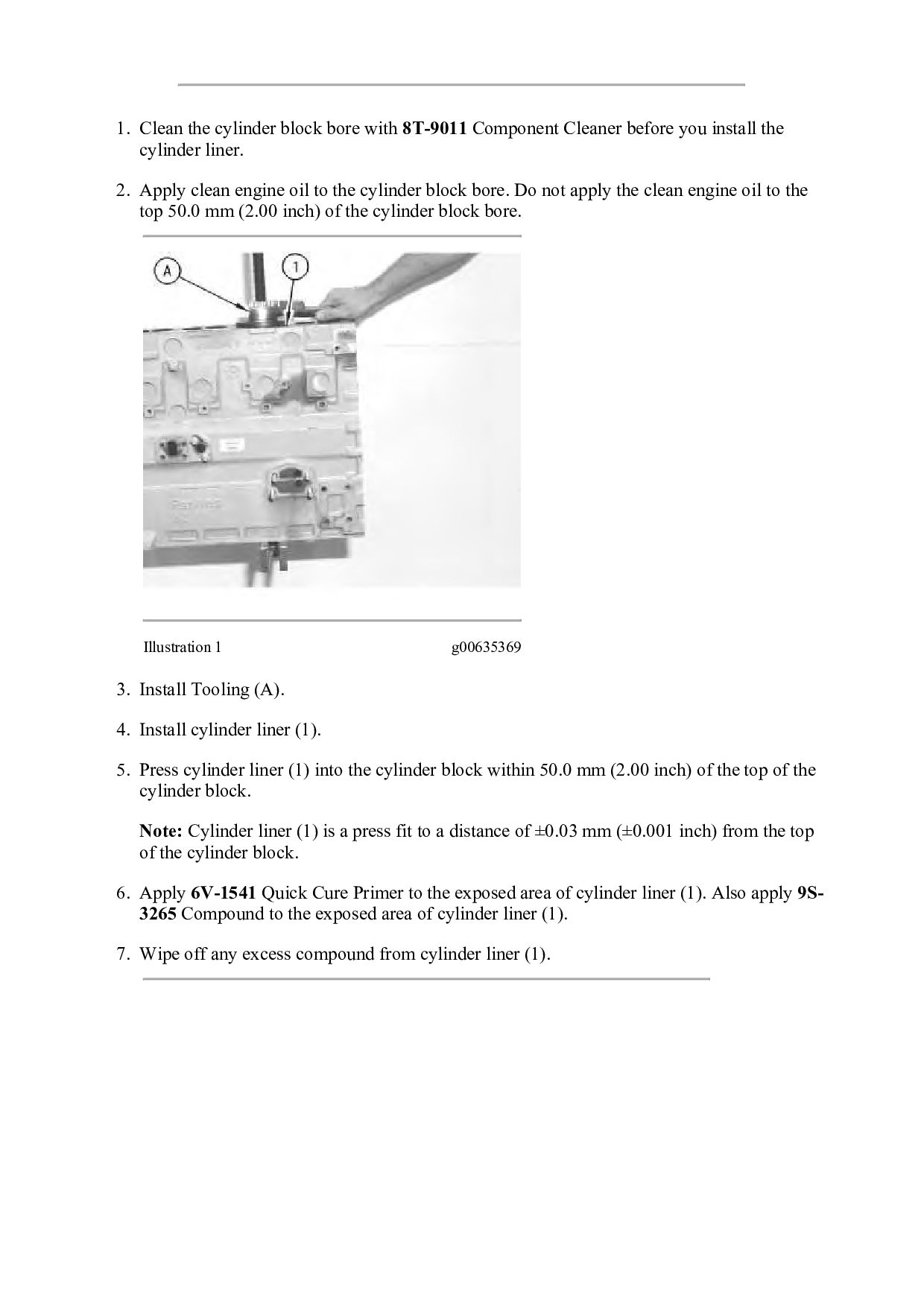
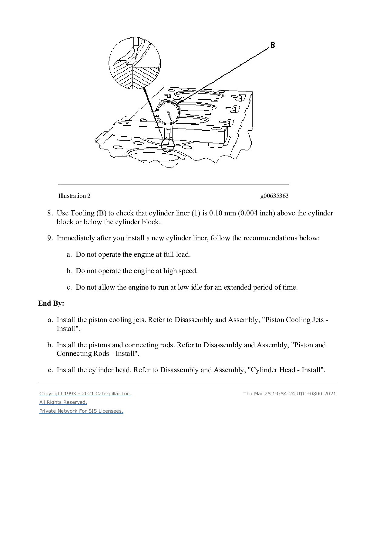
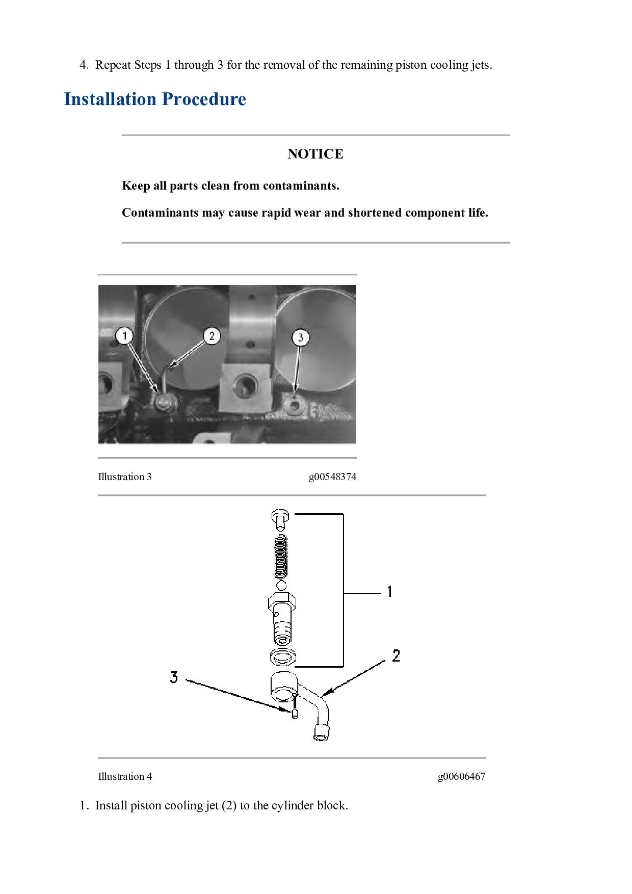
COMPACTOR DAF Configuration: CS-663E CP-663E Vibratory Compactor DAF00001-UP (MACHINE) POWERED BY 3056E Engine Disassembly and Assembly 3056E Engine for Caterpillar Built Machines Media Number -RENR2400-06 Publication Date -01/02/2006 Date Updated -03/05/2017 i01755583 Camshaft - Remove and Install SMCS - 1210-010 Removal Procedure Start By: a. Remove the rocker shaft assembly and the pushrods. Refer to Disassembly and Assembly, "Rocker Shaft and Pushrod - Remove". b. Remove the fuel transfer pump. Refer to Disassembly and Assembly, "Fuel Transfer Pump - Remove". c. Remove the front housing. Refer to Disassembly and Assembly, "Housing (Front) - Remove". d. Remove the camshaft gear. Refer to Disassembly and Assembly, "Camshaft Gear - Remove and Install". NOTICE Keep all parts clean from contaminants. Contaminants may cause rapid wear and shortened component life. NOTICE Care must be taken to ensure that fluids are contained during performance of inspection, maintenance, testing, adjusting and repair of the product. Be prepared to collect the fluid with suitable containers