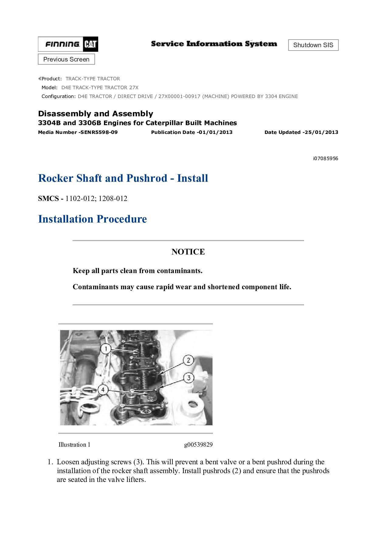
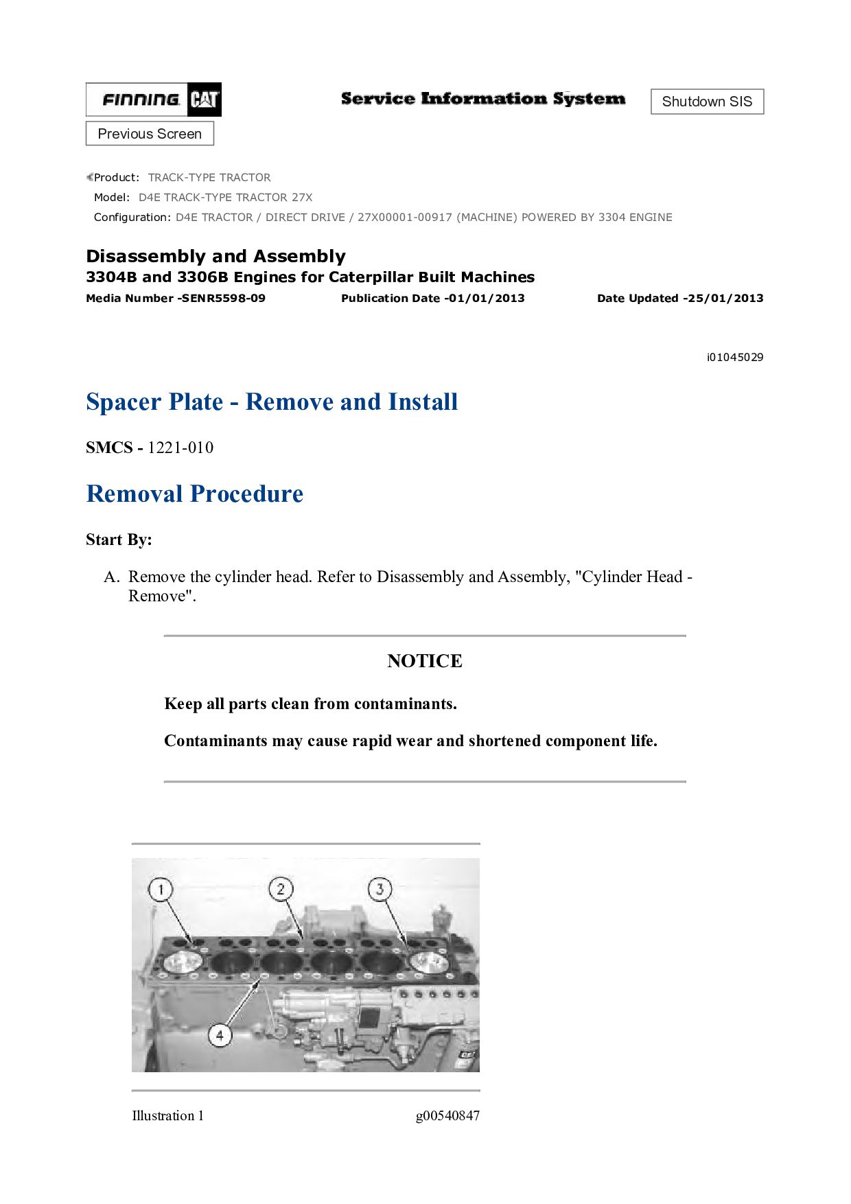
TRACTOR 27X Configuration: D4E TRACTOR / DIRECT DRIVE / 27X00001-00917 (MACHINE) POWERED BY 3304 ENGINE Disassembly and Assembly 3304B and 3306B Engines for Caterpillar Built Machines Media Number -SENR5598-09 Publication Date -01/01/2013 Date Updated -25/01/2013 i00991114 Cylinder Head - Remove SMCS - 1100-011 Removal Procedure Start By: A. Remove the fuel injection lines. Refer to Disassembly and Assembly, "Fuel Injection Lines - Remove and Install". B. Remove the exhaust manifold. Refer to Disassembly and Assembly, "Exhaust Manifold - Remove and Install". C. Remove the rocker shaft and pushrods. Refer to Disassembly and Assembly, "Rocker Shaft and Pushrods - Remove". NOTICE Keep all parts clean from contaminants. Contaminants may cause rapid wear and shortened component life. NOTICE Care must be taken to ensure that fluids are contained during performance of inspection, maintenance, testing, adjusting and repair of the machine. Be prepared to collect the fluid with suitable containers before opening any compartment or disassembling any component containing fluids.