Interfaces Kedarnath Kolluri and Michael Demkowicz Financial Support: Center for Materials at Irradiation and Mechanical Extremes (CMIME) at LANL, an Energy Frontier Research Center (EFRC) funded by U.S. Department of Energy, Office of Science, Office of Basic Energy Sciences Acknowledgments: B. P. Uberuaga, A. Kashinath, A. Vattré, X.-Y. Liu, A. Misra, R. G. Hoagland, J. P. Hirth, M. A. Nastasi, and A. Caro
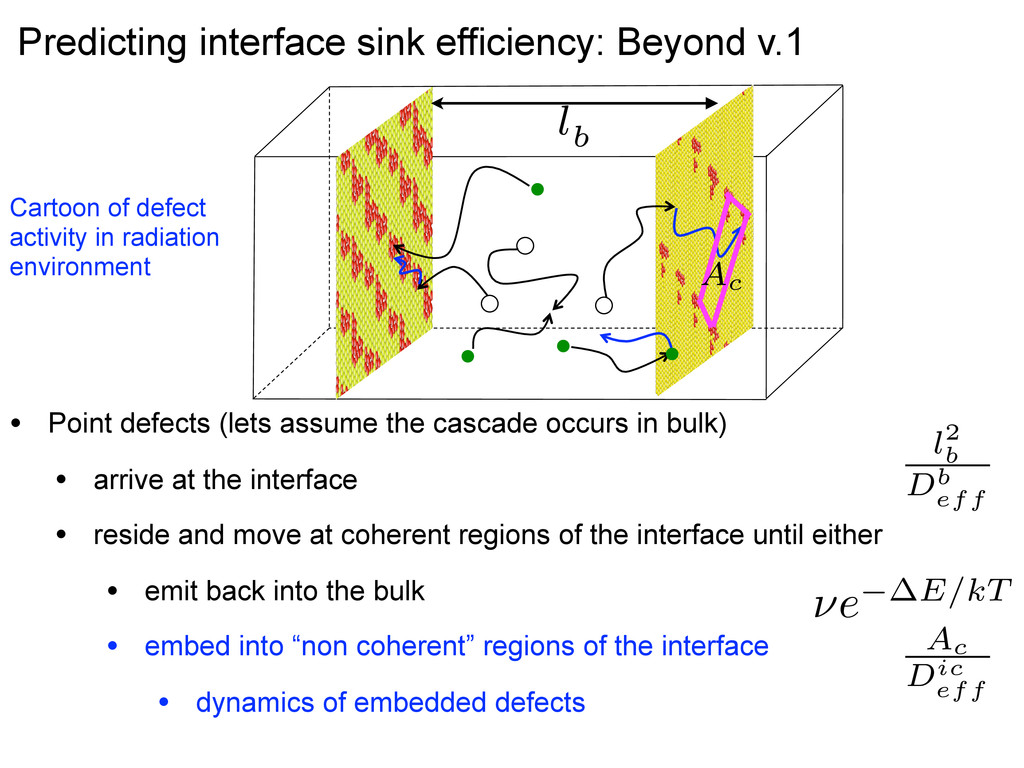
• arrive at the interface • reside and move at coherent regions of the interface until either • emit back into the bulk • embed into “non coherent” regions of the interface • dynamics of embedded defects Predicting interface sink efficiency: Beyond v.1 Cartoon of defect activity in radiation environment l2 b Db eff ⌫e E/kT Ac Dic eff l2 b Db eff Ac Dic eff
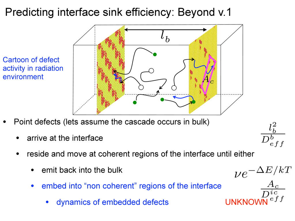
• arrive at the interface • reside and move at coherent regions of the interface until either • emit back into the bulk • embed into “non coherent” regions of the interface • dynamics of embedded defects UNKNOWN Cartoon of defect activity in radiation environment l2 b Db eff ⌫e E/kT Ac Dic eff l2 b Db eff Ac Dic eff Predicting interface sink efficiency: Beyond v.1
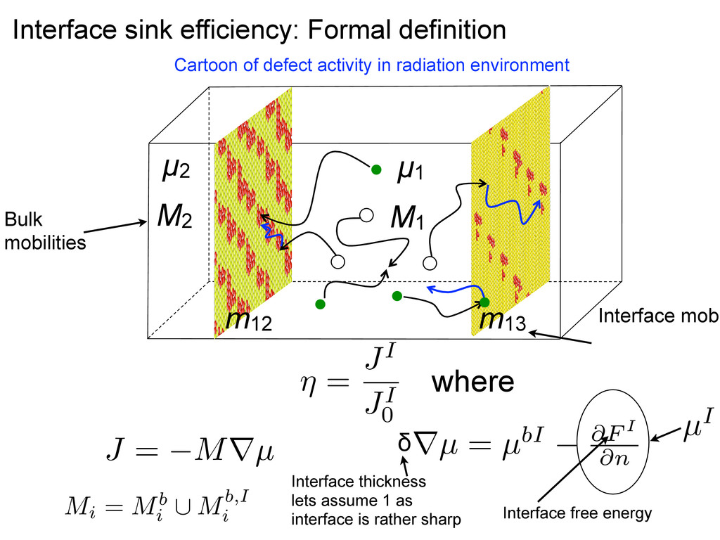
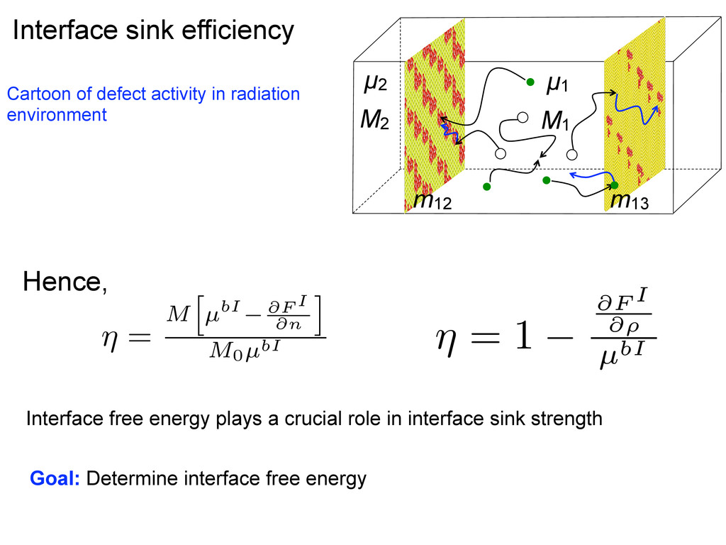
radiation environment where M2 µ2 M1 µ1 m13 m12 ⌘ = JI JI 0 Mi = Mb i [ Mb,I i Bulk mobilities Interface mobi Interface free energy µI J = Mrµ rµ = µbI @F I @n δ Interface thickness lets assume 1 as interface is rather sharp
Hence, Interface free energy plays a crucial role in interface sink strength Goal: Determine interface free energy ⌘ = M h µbI @F I @n i M0µbI ⌘ = 1 @F I @⇢ µbI M2 µ2 M1 µ1 M3 µ3 m13 m12
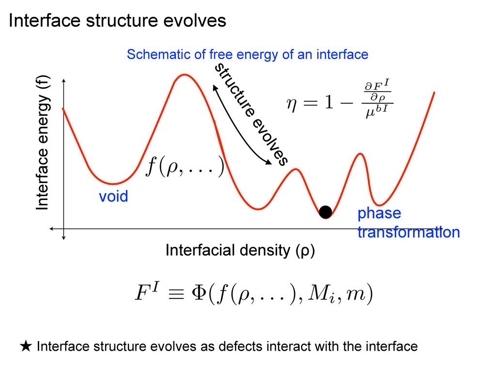
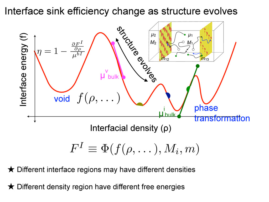
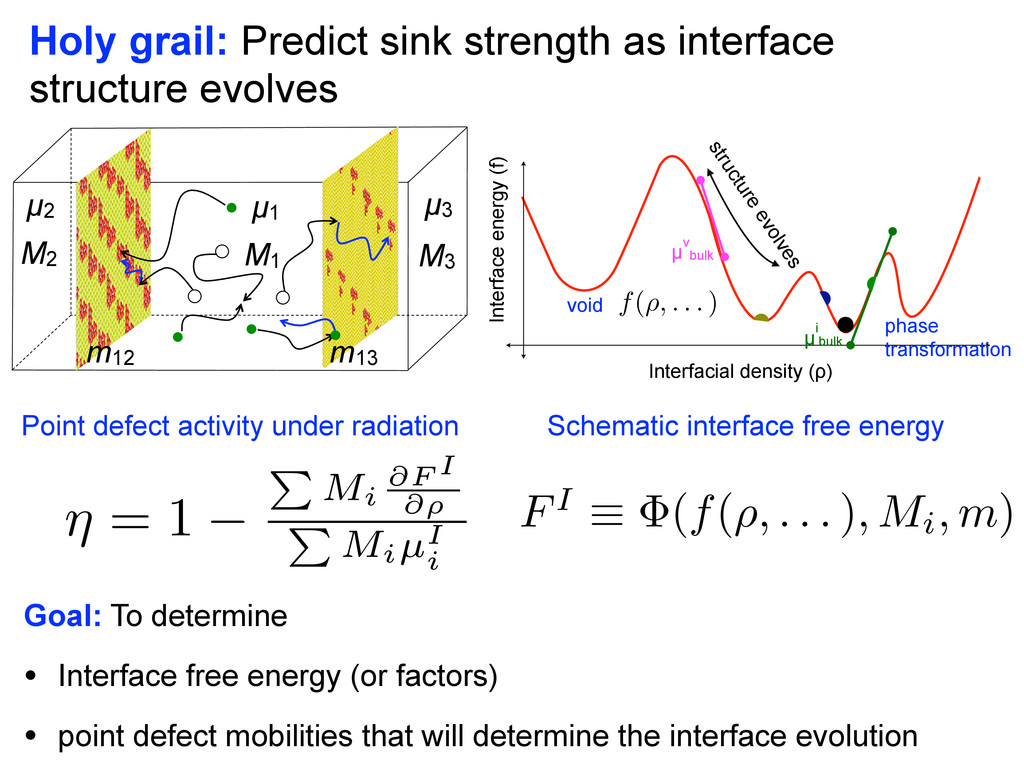
density region have different free energies Interface sink efficiency change as structure evolves Interfacial density (ρ) Interface energy (f) µ v bulk µ i bulk void phase transformation structure evolves f(⇢, . . . ) FI ⌘ (f(⇢, . . . ), Mi, m) ⌘ = 1 @F I @⇢ µbI M2 µ2 M1 µ1 M3 µ3 m13 m12
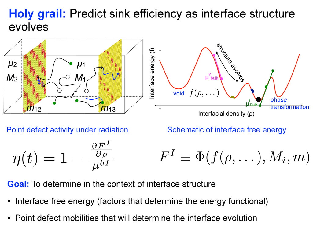
of interface free energy Point defect activity under radiation Interfacial density (ρ) Interface energy (f) µ v bulk µ i bulk void phase transformation structure evolves f(⇢, . . . ) FI ⌘ (f(⇢, . . . ), Mi, m) Goal: To determine in the context of interface structure • Interface free energy (factors that determine the energy functional) • Point defect mobilities that will determine the interface evolution ⌘(t) = 1 @F I @⇢ µbI M2 µ2 M1 µ1 M3 µ3 m13 m12
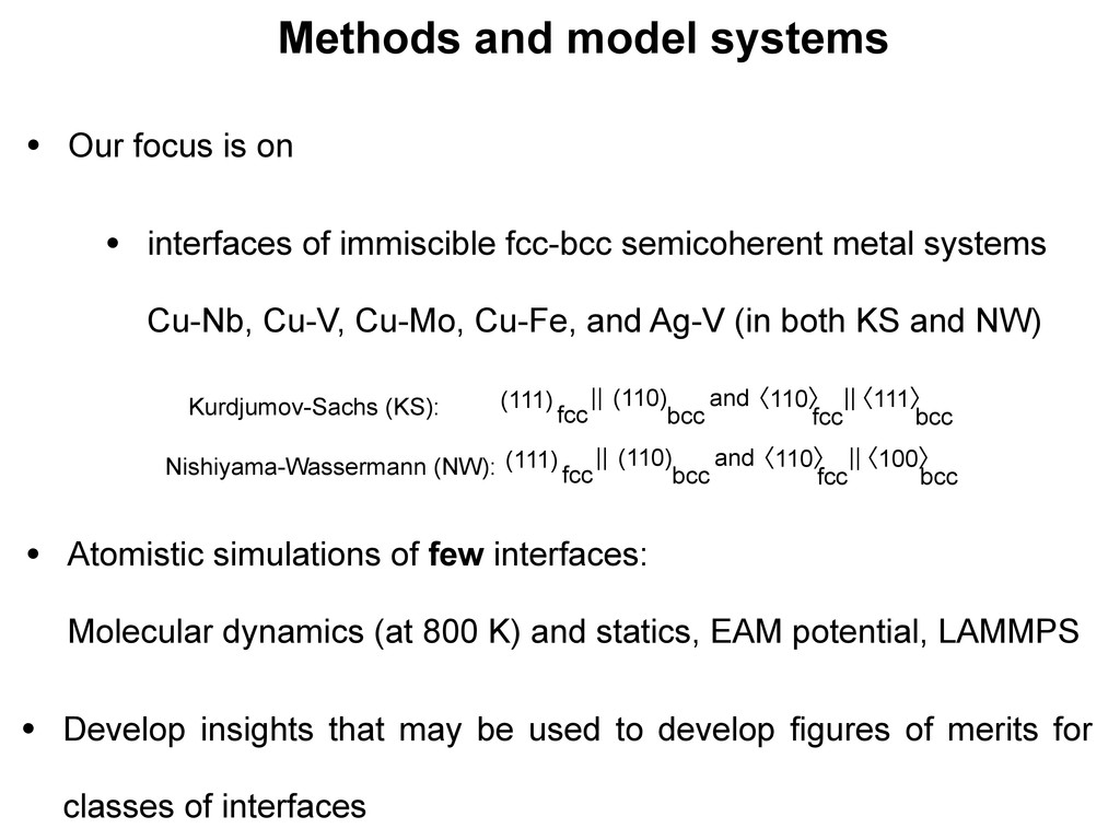
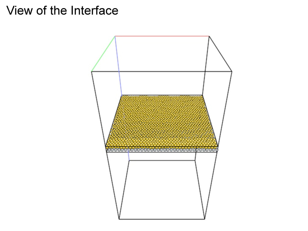
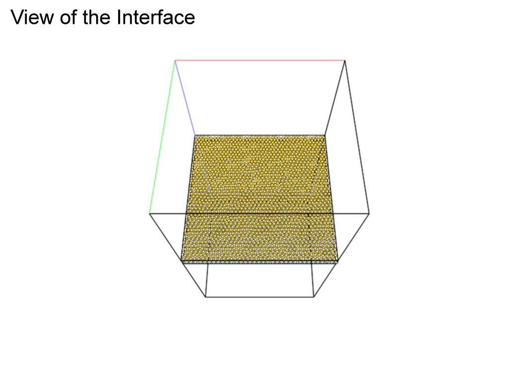
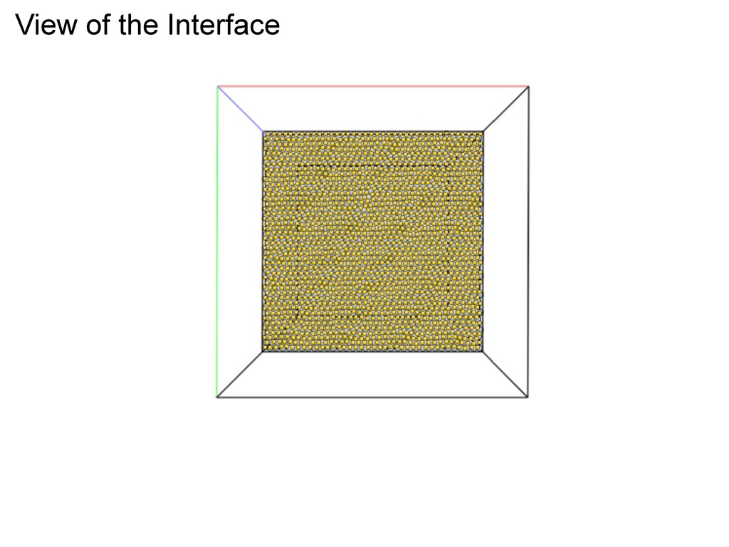
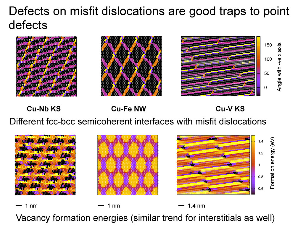
semicoherent metal systems Cu-Nb, Cu-V, Cu-Mo, Cu-Fe, and Ag-V (in both KS and NW) Methods and model systems • Atomistic simulations of few interfaces: Molecular dynamics (at 800 K) and statics, EAM potential, LAMMPS • Develop insights that may be used to develop figures of merits for classes of interfaces (111) fcc (110) bcc || ʪ110ʫ fcc ʪ111ʫ bcc || and Kurdjumov-Sachs (KS): (111) fcc (110) bcc || ʪ110ʫ fcc ʪ100ʫ bcc || and Nishiyama-Wassermann (NW):
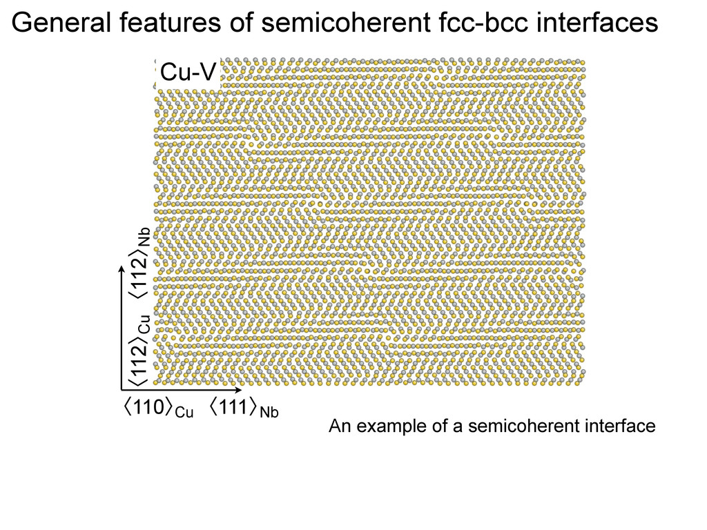
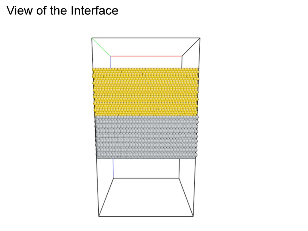
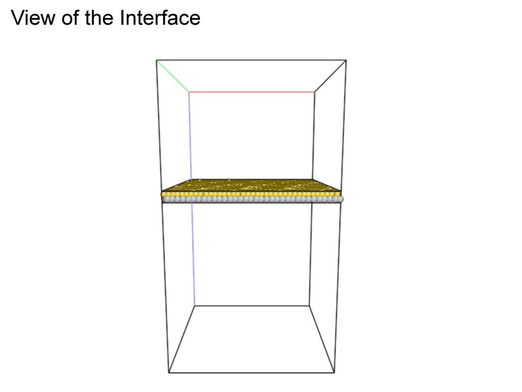
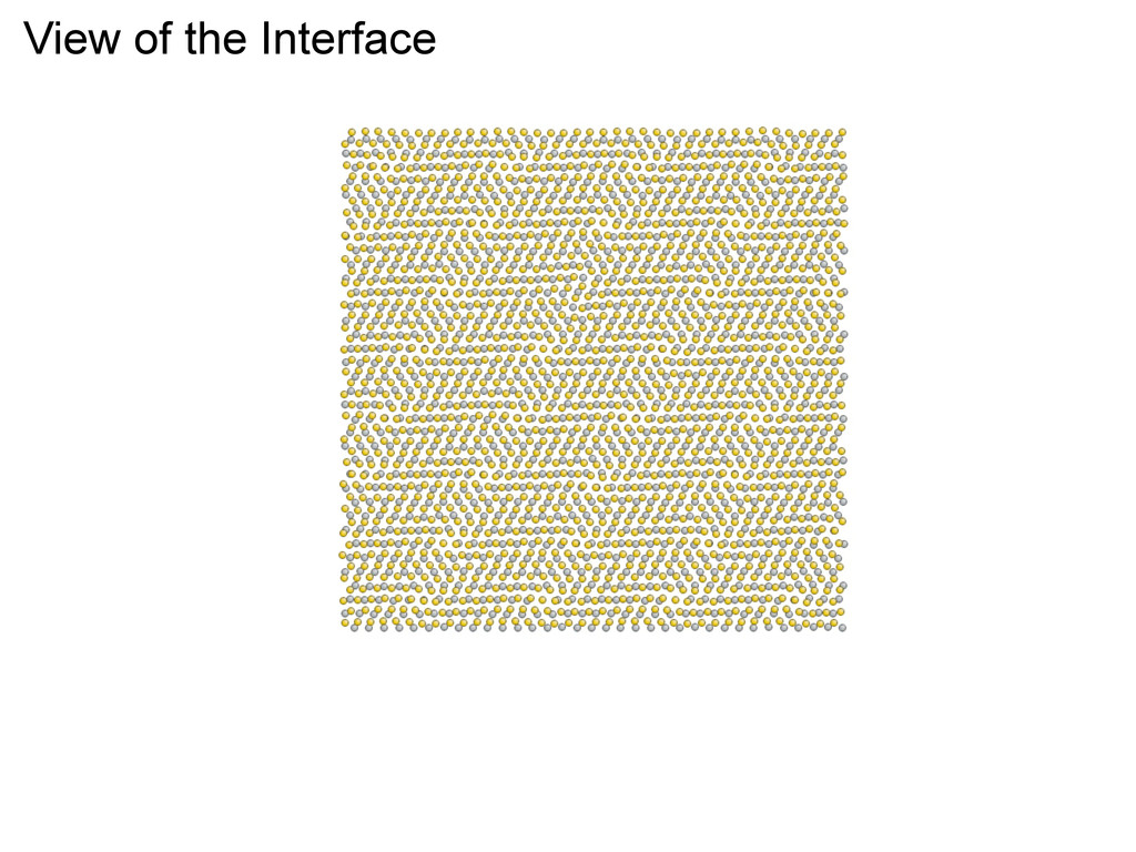
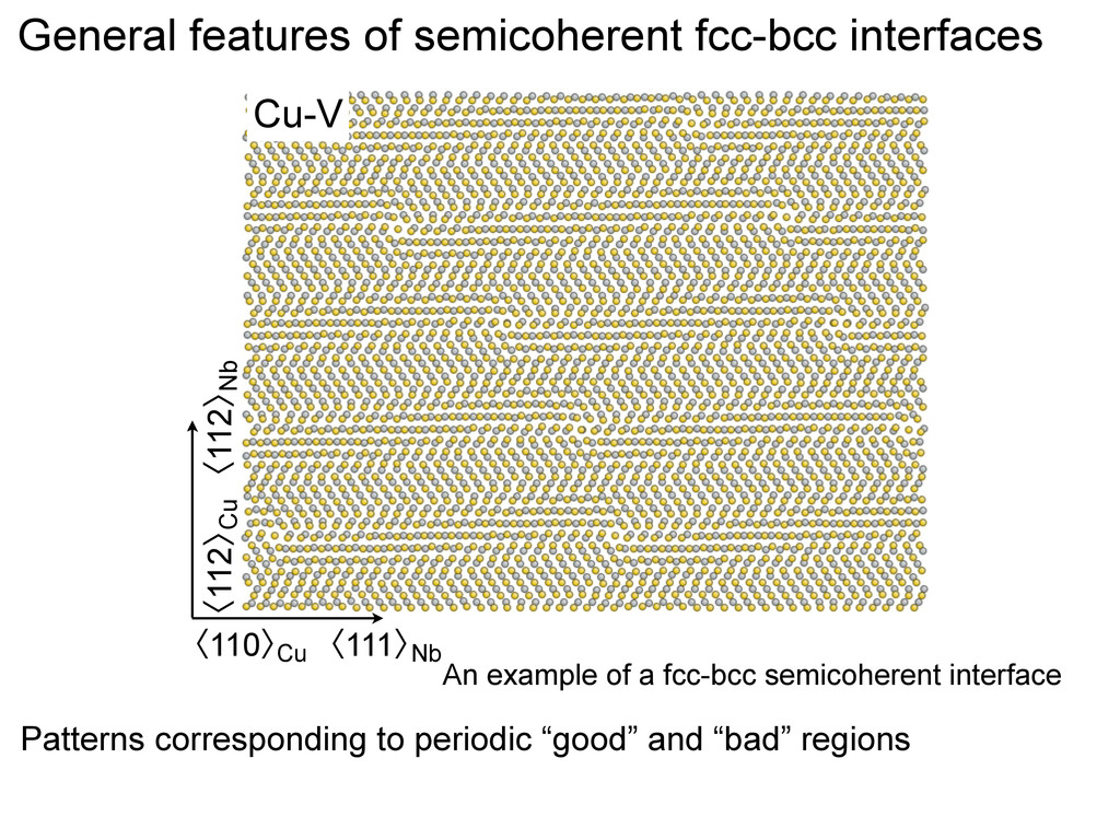
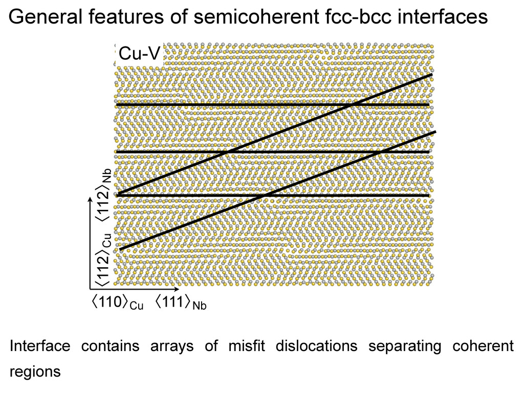
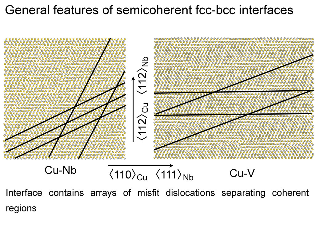
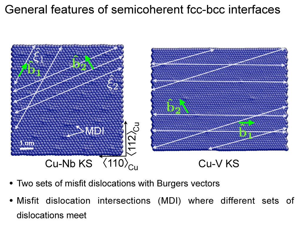
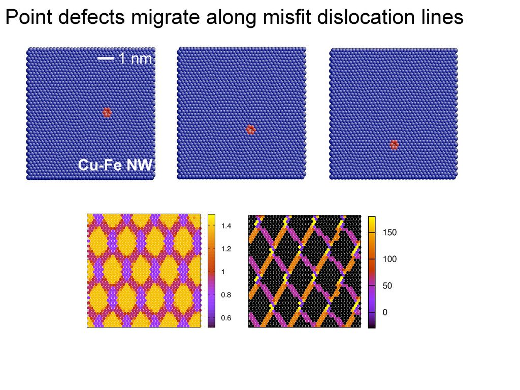
MDI • Two sets of misfit dislocations with Burgers vectors • Misfit dislocation intersections (MDI) where different sets of dislocations meet General features of semicoherent fcc-bcc interfaces
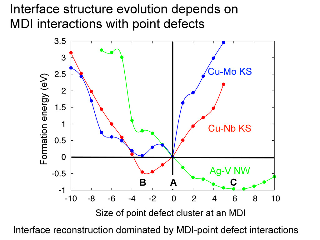
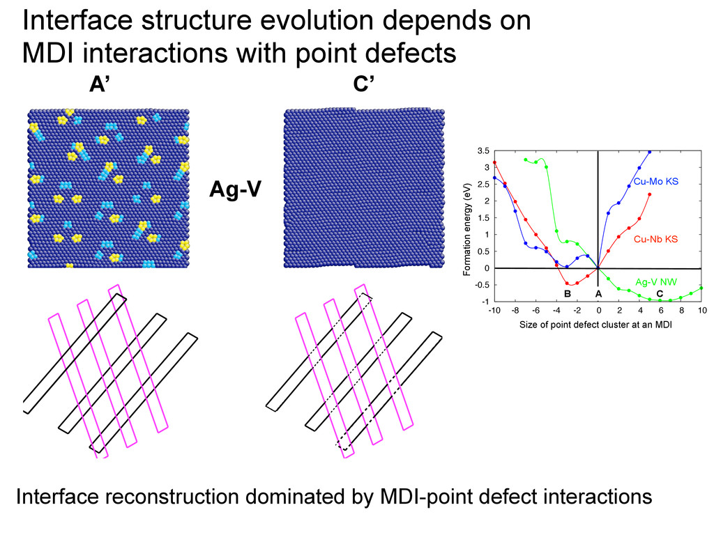
depends on MDI interactions with point defects Formation energy (eV) Ag-V NW Cu-Nb KS Size of point defect cluster at an MDI -1 -0.5 0 0.5 1 1.5 2 2.5 3 3.5 -10 -8 -6 -4 -2 0 2 4 6 8 10 Cu-Mo KS B C A
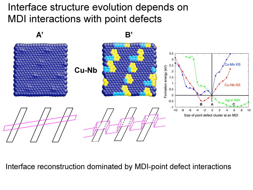
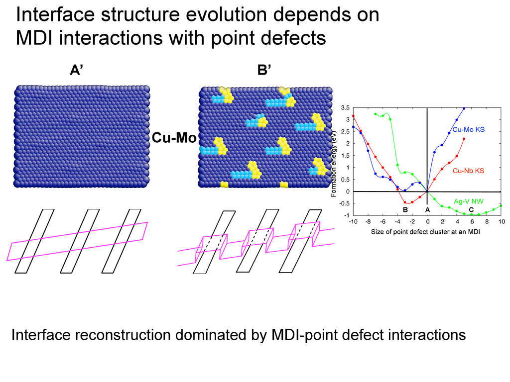
depends on MDI interactions with point defects Formation energy (eV) Ag-V NW Cu-Nb KS Size of point defect cluster at an MDI -1 -0.5 0 0.5 1 1.5 2 2.5 3 3.5 -10 -8 -6 -4 -2 0 2 4 6 8 10 Cu-Mo KS B C A B’ A’ Cu-Nb
with point defects Interface reconstruction dominated by MDI-point defect interactions Formation energy (eV) Ag-V NW Cu-Nb KS Size of point defect cluster at an MDI -1 -0.5 0 0.5 1 1.5 2 2.5 3 3.5 -10 -8 -6 -4 -2 0 2 4 6 8 10 Cu-Mo KS B C A
interface free energy Point defect activity under radiation ⌘ = 1 P Mi @F I @⇢ P MiµI i Interfacial density (ρ) Interface energy (f) µ v bulk µ i bulk void phase transformation structure evolves f(⇢, . . . ) M2 µ2 M1 µ1 M3 µ3 m13 m12 FI ⌘ (f(⇢, . . . ), Mi, m) Goal: To determine • Interface free energy (or factors) • point defect mobilities that will determine the interface evolution
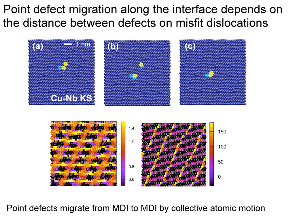
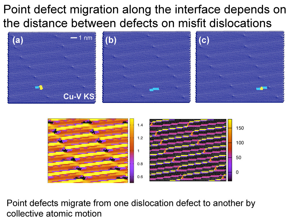
of the interface • In semicoherent fcc-bcc interfaces, interface sink strength depends on – Density of misfit dislocation intersections and other dislocation defects – The ability of the misfit dislocation intersections to trap point defects – Point defect transport along the interfaces • Distance between misfit dislocation defects • character of the misfit dislocations