Upgrade to Pro — share decks privately, control downloads, hide ads and more …

dislocation model of migration

dislocation model of migration

Kedar Kolluri

May 05, 2012
Tweet

More Decks by Kedar Kolluri

Other Decks in Research

Transcript

  1. Dislocation model for interface migration Kedarnath Kolluri and M. J.

    Demkowicz Financial Support: Center for Materials at Irradiation and Mechanical Extremes (CMIME) at LANL, an Energy Frontier Research Center (EFRC) funded by U.S. Department of Energy, Office of Science, Office of Basic Energy Sciences Acknowledgments: B. Uberuaga, X.-Y. Liu, A. Caro, and A. Misra
  2. • This deck contains only the dislocation model for migration

    of isolated vacancies and intersitials at CuNb KS interface • The atomistic results are available at • http://bit.ly/cunb-defect-migrate • The link to papers published with these and other results are • http://bit.ly/cunb-migrate-paper • http://bit.ly/cunb-pointdefects-paper
  3. b1 !1 Set 2 Set 1 L a2 a1 Set

    1 Set 2 a1 a2 L L b1 !1 b1 !1 Set 1 Set 2 3L • Thermal kink pairs nucleating at adjacent MDI mediate the migration • Migration barriers 1/3rd that of migration barriers in bulk KJ1 KJ3´ KJ4 Cu ʪ112ʫ ʪ110ʫ Cu KJ2´ KJ4 KJ3 KJ2 KJ1 Cu ʪ112ʫ ʪ110ʫ Cu a b I Vacancy Step 1 ! (reaction coordinate) t a I t t b " E (eV) 0 0.05 0.1 0.15 0.2 0.25 0.3 0.35 0.4 0.45 0 0.1 0.2 0.3 0.4 0.5 0.6 0.7 0.8 0. t I t b t "Ea-b = 0.06 - 0.12 eV "Ea-I = 0.25 - 0.35 eV "Ea-t = 0.35 - 0.45 eV Vacancy Interstitial Isolated point defects in CuNb migrate from one MDI to another
  4. b1 !1 Set 2 Set 1 L a2 a1 Set

    1 Set 2 a1 a2 L L b1 !1 b1 !1 Set 1 Set 2 3L KJ1 KJ3´ KJ4 Cu ʪ112ʫ ʪ110ʫ Cu KJ2´ KJ4 KJ3 KJ2 KJ1 Cu ʪ112ʫ ʪ110ʫ Cu a b I Vacancy Step 1 ! (reaction coordinate) t a I t t b " E (eV) 0 0.05 0.1 0.15 0.2 0.25 0.3 0.35 0.4 0.45 0 0.1 0.2 0.3 0.4 0.5 0.6 0.7 0.8 0. t I t b t "Ea-b = 0.06 - 0.12 eV "Ea-I = 0.25 - 0.35 eV "Ea-t = 0.35 - 0.45 eV Vacancy Interstitial Isolated point defects in CuNb migrate from one MDI to another • Thermal kink pairs nucleating at adjacent MDI mediate the migration • Migration barriers 1/3rd that of migration barriers in bulk
  5. Set 2 b1 !1 a1 a2 Set 1 L L

    b1 !1 Set 1 Set 2 b1 !1 Set 1 Set 2 3L KJ1 KJ3´ KJ4 KJ2´ Cu ʪ112ʫ ʪ110ʫ Cu c b I Vacancy Step 2 ! (reaction coordinate) t a I t t b " E (eV) 0 0.05 0.1 0.15 0.2 0.25 0.3 0.35 0.4 0.45 0 0.1 0.2 0.3 0.4 0.5 0.6 0.7 0.8 0. t I t b t "Ea-b = 0.06 - 0.12 eV "Ea-I = 0.25 - 0.35 eV "Ea-t = 0.35 - 0.45 eV Vacancy Interstitial Thermal kink pairs aid the migration process • Thermal kink pairs nucleating at adjacent MDI mediate the migration • Migration barriers 1/3rd that of migration barriers in bulk
  6. Restrictions/Simplifications for dislocation model 1. Isotropic linear elastic solutions for

    dislocation interactions 2. Interactions are considered between kinks/jogs and set 1 dislocation only 3. Interactions neglected between kinks/jogs and the dislocation network Point defect is a dislocation mechanism b1 !1 Set 2 Set 1 a L a2 a1 I1 b1 !1 Set 1 Set 2 a1 a2 L L b1 !1 Set 1 Set 2 b 3L (a) (b) (c)
  7. created due to the nucleation of a kink-jog pair, each

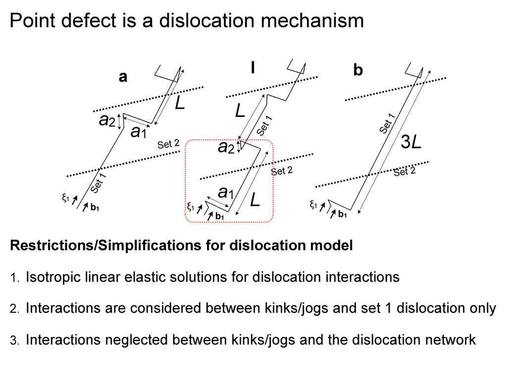
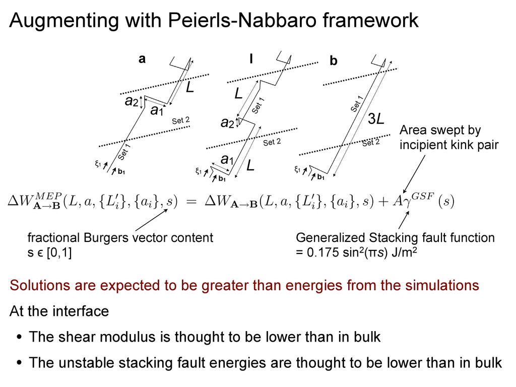
    of length ai , and separated by L⇥ i (a function of L and ai ) and is given by Eqn.(3), and the third term is the self energy of the dislocation segments that form the kink-jog pair. In Eqns. (2) and (3), µ = 42 GPa is the shear modulus of bulk copper and b = aCu ⇤ 2 is the magnitude of the Burgers vector of all the dislocation segments; aCu is the 0 K lattice constant of copper. From simulations, we obtain a1 = aCu ⇤ 3 , a2 = aCu ⇤ 2 , and L = 3aCu ⇤ 2 . Energy expressions for all the states in our simulations are readily obtained as a combination of Eqns. (2) and (3) with appropriate values for the variables L, L⇥ i , and ai . W(L, a, {L⇥ i }, {ai }) = 2 Wdis inter (L, ⇥, a) + ⌥ i Wjog inter (L⇥ i , ai ) + ⌥ i 2 µb2ai 4⇧(1 ⌅) ln ai b ⇥ Wdis inter (L, ⇥, a) = µb2 4⇧ ⇧ ⇧ L2 + a2 L a + L ln ⇤ 2L ⇧ L2 + a2 + L ⌅⌃ Wjog inter (L, a) = µb2 4⇧(1 ⌅) ⇧ 2L 2 ⇧ L2 + a2 2a ln ⇤ L ⇧ L2 + a2 + a ⌅⌃ WMEP A B (L, a, {L⇥ i }, {ai }, s) = WA B(L, a, {L⇥ i }, {ai }, s) + A⇥GSF (s) The parameter is related to the dislocation (in this case, jogs and kinks) core radius and can not be estimated within the linear elastic theory of dislocations. We obtain = 0.448 by fitting the energy, E = 0.27 eV, of the kink pair configuration corresponding to the configuration in Fig. 1[schematic of the kink pair is marked in Fig. 5(b) and] from our • α can not be determined with in linear elastic theory of dislocations • α = 0.458 is obtained by fitting the expression for formation energy of a thermal kink pair from simulations (ΔE = 0.27 eV) Thermal kink pair configuration Dislocation model for point defect migration b1 !1 Set 2 Set 1 a L a2 a1 I1 b1 !1 Set 1 Set 2 a1 a2 L L b1 !1 Set 1 Set 2 b 3L (a) (b) (c) J. P. Hirth and J. Lothe, Theory of Dislocations, (Wiley, New York, 1982)
  8. Solutions are expected to be greater than energies from the

    simulations At the interface • The shear modulus is thought to be lower than in bulk • The unstable stacking fault energies are thought to be lower than in bulk are readily obtained as a combination of Eqns. (2) and (3) with appropriate valu variables L, L⇥ i , and ai . W(L, a, {L⇥ i }, {ai }) = 2 Wdis inter (L, ⇥, a) + ⌥ i Wjog inter (L⇥ i , ai ) + ⌥ i 2 µb 4⇧(1 Wdis inter (L, ⇥, a) = µb2 4⇧ ⇧ ⇧ L2 + a2 L a + L ln ⇤ 2L ⇧ L2 + a2 + L ⌅⌃ Wjog inter (L, a) = µb2 4⇧(1 ⌅) ⇧ 2L 2 ⇧ L2 + a2 2a ln ⇤ L ⇧ L2 + a2 + WMEP A B (L, a, {L⇥ i }, {ai }, s) = WA B(L, a, {L⇥ i }, {ai }, s) + A⇥GSF (s) The parameter is related to the dislocation (in this case, jogs and kinks) core r can not be estimated within the linear elastic theory of dislocations. We obtain by fitting the energy, E = 0.27 eV, of the kink pair configuration correspond configuration in Fig. 1[schematic of the kink pair is marked in Fig. 5(b) and] 7 Generalized Stacking fault function = 0.175 sin2(πs) J/m2 Area swept by incipient kink pair fractional Burgers vector content s ϵ [0,1] b1 !1 Set 2 Set 1 L a2 a1 a b1 !1 Set 1 Set 2 b 3L I b1 !1 Set 1 Set 2 a1 a2 L L Augmenting with Peierls-Nabbaro framework
  9. Entire migration path can be predicted Key inputs to the

    dislocation model • Interface misfit dislocation distribution • Structure of the accommodated point defects Analysis of the interface structure may help predict quantitatively point-defect behavior at other semicoherent interfaces Δ E (eV) s s 0 0.05 0.1 0.15 0.2 0.25 0.3 0.35 0.4 0.45 0.5 0.55 0 0.1 0.2 0.3 0.4 0.5 0.6 0.7 0.8 0.9 1 I a 0 0.05 0.1 0.15 0.2 0.25 0.3 0.35 0.4 0.45 0.5 0 0.1 0.2 0.3 0.4 0.5 0.6 0.7 0.8 0.9 1 b I Dislocation model Atomistics K. Kolluri and M. J. Demkowicz, Phys Rev B, 82, 193404 (2010) KJ1 KJ3´ KJ4 Cu ʪ112ʫ ʪ110ʫ Cu KJ2´ KJ4 KJ3 KJ2 KJ1
  10. It should be easier for this to happen! L/Lo ΔW

    (eV) 0 0.02 0.04 0.06 0.08 0.1 0.12 1 1.5 2 2.5 3 from dislocation model • Migration of a jog, one neighbor at a time, should occur readily according to linear elastic theory of dislocations • This mechanism, however, is not observed in atomic-scale simulations b1 !1 Set 2 Set 1 L a2 a1 a b1 !1 Set 1 Set 2 b 3L I b1 !1 Set 1 Set 2 a1 a2 L L
  11. Energy and activation volume in alternate scenario from atomistic calculations

    0 0.2 0.4 0.6 0.8 1 1.2 1.4 0 1 2 3 4 5 6 0 0.1 0.2 0.3 0.4 0.5 0.6 !E (eV) !V/"o S !E !Ejog core !V/"o !W 0 0.2 0.4 0.6 0.8 1 1.2 1.4 0 1 2 3 4 5 !E (eV) S !E !Ejog core !V/"o !W 0 0.2 0.4 0.6 0.8 1 0 1 2 3 4 5 6 0 0.1 0.2 0.3 0.4 S !E !Ejog core !V/"o !W 2 3 4 5 6 0 0.1 0.2 0.3 0.4 0.5 !V/"o !E !Ejog core !V/"o !W 0 0.2 0.4 0.6 0.8 1 1.2 1.4 0 1 2 3 4 5 6 0 0.1 0.2 0.3 0.4 0.5 0.6 !E (eV) !V/"o S !E !Ejog core !V/"o !W 0 0.2 0.4 0.6 0.8 1 1.2 1.4 0 1 2 3 4 5 6 0 0.1 0.2 0.3 0.4 0.5 0.6 !E (eV) !V/"o S !E !Ejog core !V/"o !W 0 0.2 0.4 0.6 0.8 1 1.2 1.4 0 1 2 3 4 5 6 0 0.1 0.2 0.3 0.4 0.5 0.6 !E (eV) !V/"o S !E !Ejog core !V/"o !W 0 0.2 0.4 0.6 0.8 1 1.2 0 1 2 3 4 5 6 0 0.1 0.2 0.3 0.4 0.5 !E (eV) !V/"o S !E !Ejog core !V/"o !W dislocation model Energy differences from manually constructed atomic configurations Energy differences for few atoms surrounding the moving jog activation volume of the moving jog
  12. Position of the jog (x-axis for previous plot) S =

    6 5 4 3 2 1 6 0 first jog (stationary) is here
  13. • The barrier for atomistics is much greater than that

    from dislocation model! • The barrier in this path can be thought of as the difference in the formation energies of the jog at the MDI and on set 1 misfit dislocation • In this interface, the barrier is much larger than that we observed (but there may be other interfaces where such a mechanism could occur) The self energies of the jog change with position Not accounted for in the dislocation model S = 6 5 4 3 2 1 6 0 0 0.2 0.4 0.6 0.8 1 1.2 1.4 0 1 2 3 4 5 6 0 0.1 0.2 0.3 0.4 0.5 0.6 !E (eV) !V/"o S !E !Ejog core !V/"o !W 0 0.2 0.4 0.6 0.8 1 1.2 1.4 0 1 2 3 4 5 6 0 0.1 0.2 0.3 0.4 0.5 0.6 !E (eV) !V/"o S !E !Ejog core !V/"o !W 1 2 3 4 5 6 0 0.1 0.2 0.3 0.4 !V/"o S !E !Ejog core !V/"o !W 3 4 5 6 0 0.1 0.2 0.3 0.4 0.5 !V/"o S !E Ejog core !V/"o !W 1 2 3 4 5 6 0 0.1 0.2 0.3 0.4 0.5 0.6 !V/"o S !E !Ejog core !V/"o !W 0 2 4 6 8 1 2 4 0 1 2 3 4 5 6 0 0.1 0.2 0.3 0.4 0.5 0.6 !V/"o S !E !Ejog core !V/"o !W 0 2 4 6 8 1 2 4 0 1 2 3 4 5 6 0 0.1 0.2 0.3 0.4 0.5 0.6 !V/"o S !E !Ejog core !V/"o !W 1 2 3 4 5 6 0 0.1 0.2 0.3 0.4 0.5 0.6 !V/"o S !E !Ejog core !V/"o !W first jog (stationary) is here
  14. !" !"#$ !"#% !"#& !"#' !( !(#$ !(#% !" !(

    !$ !) !% !* !& !" !"#( !"#$ !"#) !"#% !"#* !"#& !+!,-./ !.0"1 2 !+3435-6 !+789: !.0"1 !E range of aʪ112ʫ jog on a screw dislocation in Cu !V/"o range of a ʪ112ʫjog on a screw dislocation in Cu The volume and energies of the “jog core” at S={3,4} are comparable to those of a <112> jog in a screw dislocation in bulk copper The energy differences and volumes are comparable to those for jogs in bulk screw dislocation in Cu
  15. At S = {3,4}, the migrating jog resides on set

    1 misfit dislocation and away from MDI The core energy for s={3,4} is much more than that at s={1,2,5,6} The self energies of the jog are different at different positions S = 6 5 4 3 2 1 6 0
  16. Summary • A dislocation model for point defect migration was

    developed • It is predictive! • Dislocation model applied in its originally derived form suggests that there are alternate, lower-barrier paths • However, atomistic calculations do not support that • Reason: The moving jog has different self energies along the path • This too can also be incorporated into the dislocation model