The presentation talks about various power transmitting elements that are used in Mechanical Engineering as a whole. This presentation deals with the basics of these elements for beginners to understand various aspects of it.
in Mechanical Engineering are :- ➢ Driving and driven shaft ➢ Connectors for transmission of motion and power from driving to driven shaft: belts , chains , gears , ropes , pulleys. ➢ Supporting elements : axle , bearing , brackets. ➢ Holding elements : coupling , pin ,key bolts ,nuts. Milind Pelagade 2
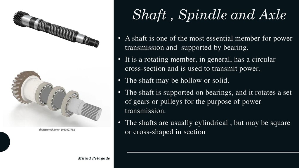
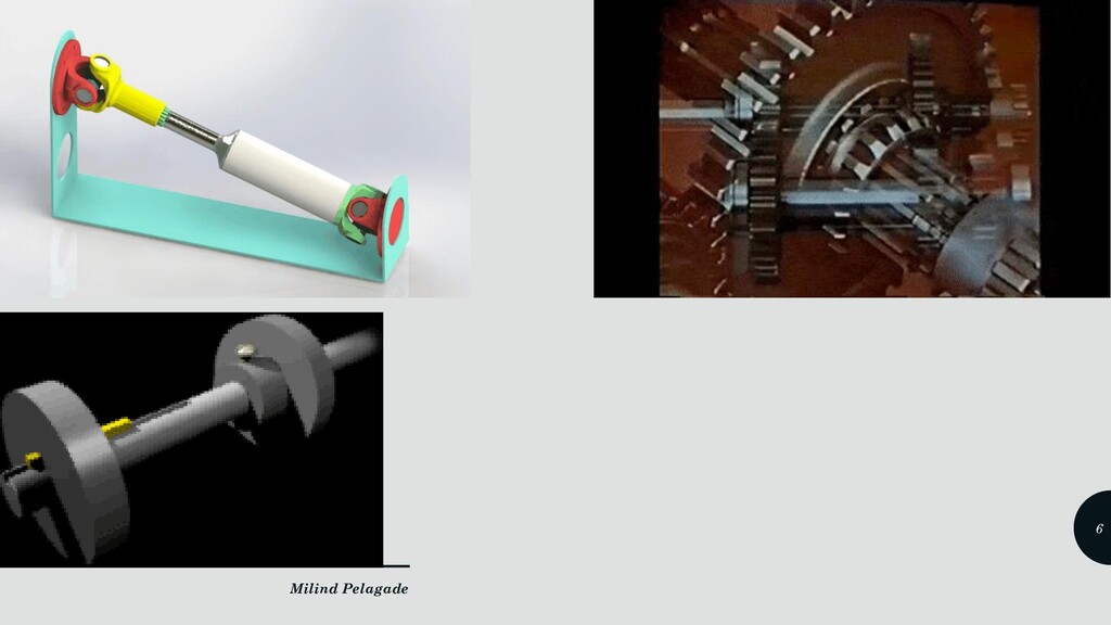
of the most essential member for power transmission and supported by bearing. • It is a rotating member, in general, has a circular cross-section and is used to transmit power. • The shaft may be hollow or solid. • The shaft is supported on bearings, and it rotates a set of gears or pulleys for the purpose of power transmission. • The shafts are usually cylindrical , but may be square or cross-shaped in section Milind Pelagade 3
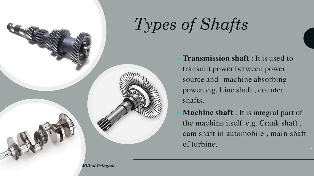
to transmit power between power source and machine absorbing power. e.g. Line shaft , counter shafts. ➢ Machine shaft : It is integral part of the machine itself. e.g. Crank shaft , cam shaft in automobile , main shaft of turbine. Milind Pelagade 4
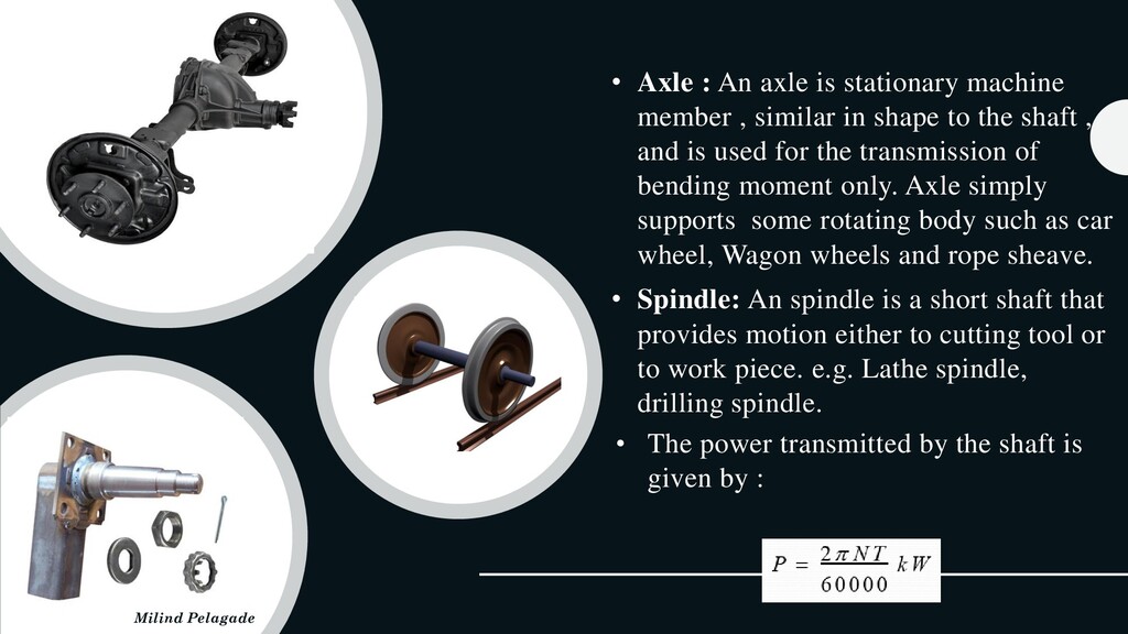
similar in shape to the shaft , and is used for the transmission of bending moment only. Axle simply supports some rotating body such as car wheel, Wagon wheels and rope sheave. • Spindle: An spindle is a short shaft that provides motion either to cutting tool or to work piece. e.g. Lathe spindle, drilling spindle. • The power transmitted by the shaft is given by : Milind Pelagade 5
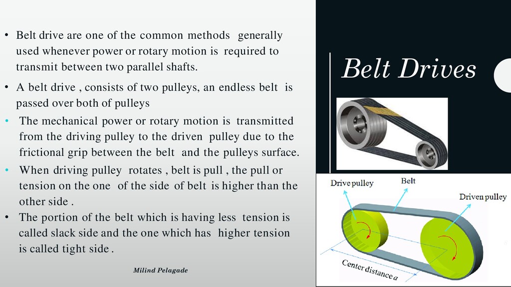
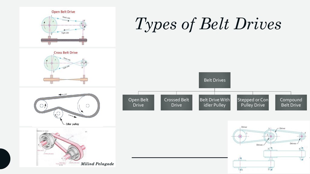
methods generally used whenever power or rotary motion is required to transmit between two parallel shafts. • A belt drive , consists of two pulleys, an endless belt is passed over both of pulleys • The mechanical power or rotary motion is transmitted from the driving pulley to the driven pulley due to the frictional grip between the belt and the pulleys surface. • When driving pulley rotates , belt is pull , the pull or tension on the one of the side of belt is higher than the other side . • The portion of the belt which is having less tension is called slack side and the one which has higher tension is called tight side . Milind Pelagade 8
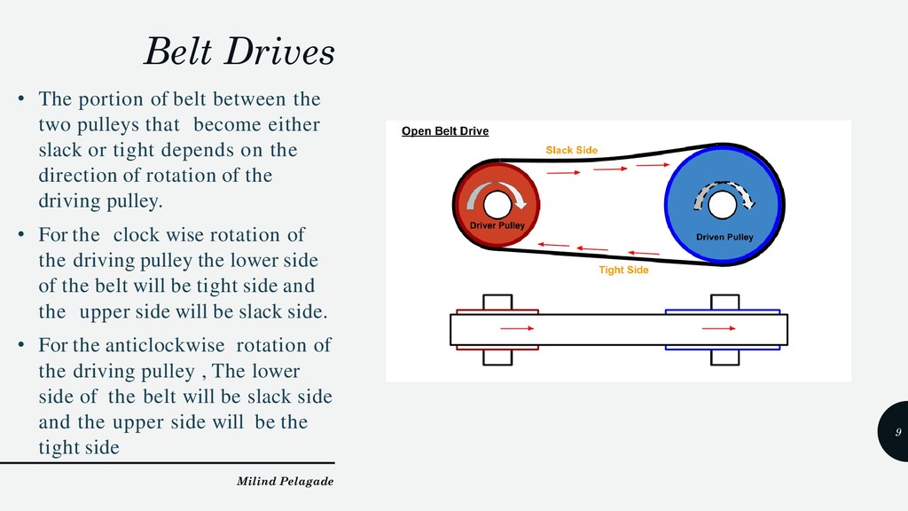
pulleys that become either slack or tight depends on the direction of rotation of the driving pulley. • For the clock wise rotation of the driving pulley the lower side of the belt will be tight side and the upper side will be slack side. • For the anticlockwise rotation of the driving pulley , The lower side of the belt will be slack side and the upper side will be the tight side Milind Pelagade 9
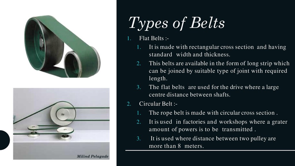
made with rectangular cross section and having standard width and thickness. 2. This belts are available in the form of long strip which can be joined by suitable type of joint with required length. 3. The flat belts are used for the drive where a large centre distance between shafts. 2. Circular Belt :- 1. The rope belt is made with circular cross section . 2. It is used in factories and workshops where a grater amount of powers is to be transmitted . 3. It is used where distance between two pulley are more than 8 meters. Milind Pelagade 11
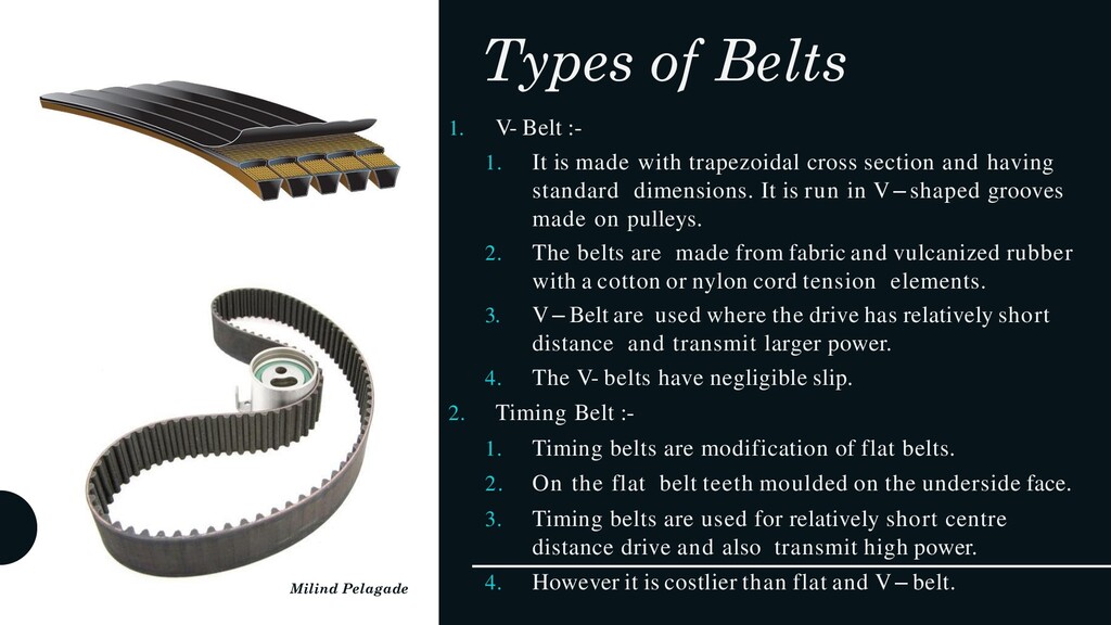
made with trapezoidal cross section and having standard dimensions. It is run in V – shaped grooves made on pulleys. 2. The belts are made from fabric and vulcanized rubber with a cotton or nylon cord tension elements. 3. V – Belt are used where the drive has relatively short distance and transmit larger power. 4. The V- belts have negligible slip. 2. Timing Belt :- 1. Timing belts are modification of flat belts. 2. On the flat belt teeth moulded on the underside face. 3. Timing belts are used for relatively short centre distance drive and also transmit high power. 4. However it is costlier than flat and V – belt. Milind Pelagade 12
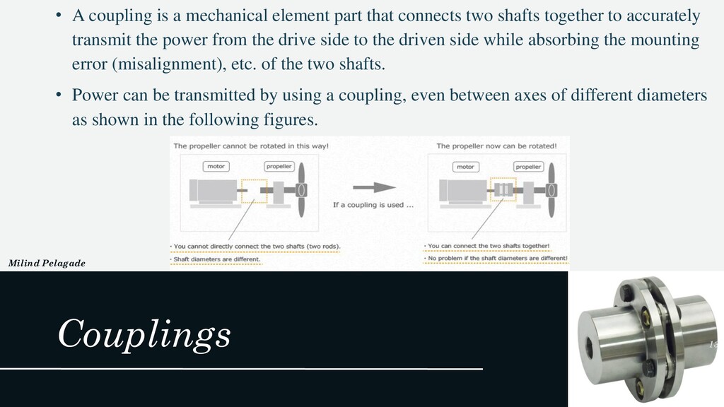
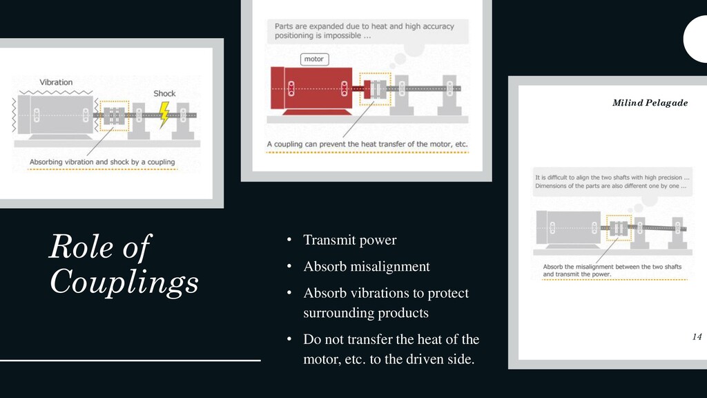
two shafts together to accurately transmit the power from the drive side to the driven side while absorbing the mounting error (misalignment), etc. of the two shafts. • Power can be transmitted by using a coupling, even between axes of different diameters as shown in the following figures. Couplings Milind Pelagade 13
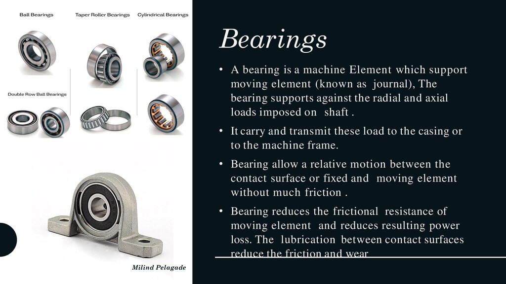
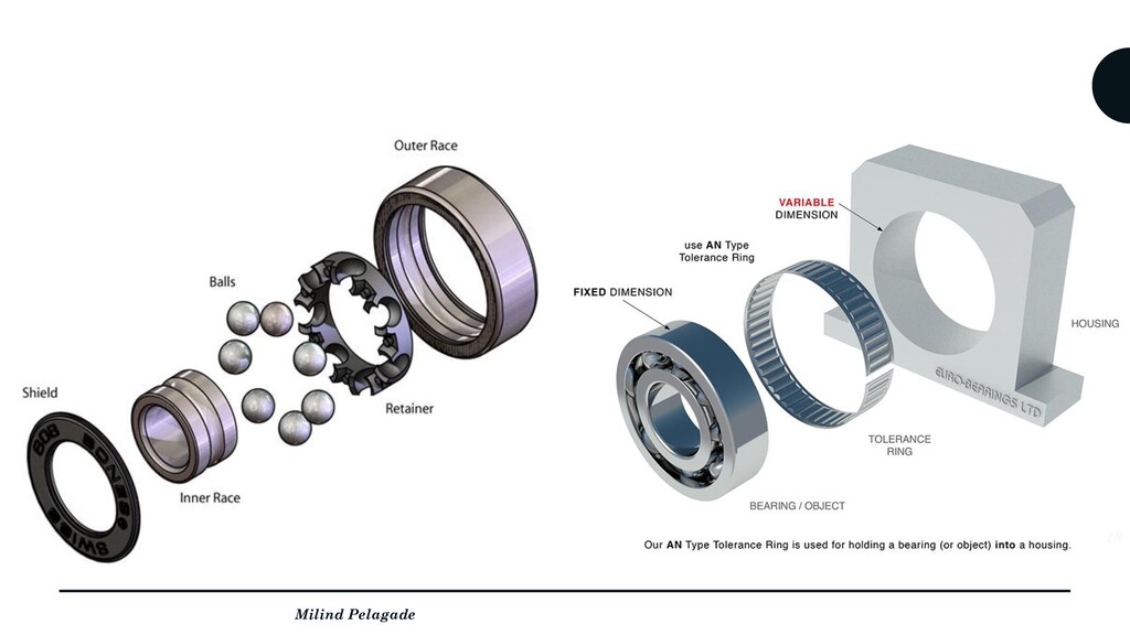
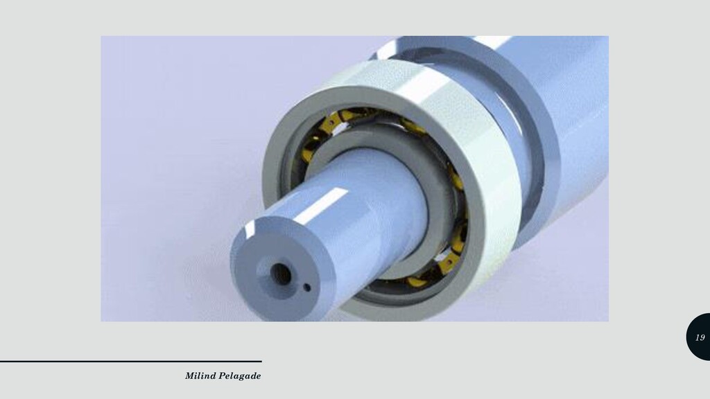
moving element (known as journal), The bearing supports against the radial and axial loads imposed on shaft . • It carry and transmit these load to the casing or to the machine frame. • Bearing allow a relative motion between the contact surface or fixed and moving element without much friction . • Bearing reduces the frictional resistance of moving element and reduces resulting power loss. The lubrication between contact surfaces reduce the friction and wear Milind Pelagade 17
as running friction is less. ➢ It can be carried radial as well as axial load. ➢ Lubrication is verysimple. ➢ Less power is wasted in friction. ➢ Replacement is easy. Milind Pelagade 20
noisy. ➢ Larger radial space is required. ➢ Initial cost ishigher. ➢ Damping of vibrationis poor. ➢ At very high speed , friction may be higher then sliding contact bearing. Milind Pelagade 21
wheel that engages another toothed mechanism to change speed or the direction of transmitted motion. • Gears are compact, positive-engagement, power transmission elements capable of changing the amount of force or torque Milind Pelagade 22
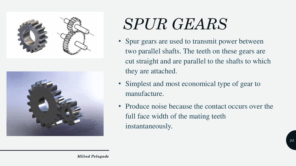
between two parallel shafts. The teeth on these gears are cut straight and are parallel to the shafts to which they are attached. • Simplest and most economical type of gear to manufacture. • Produce noise because the contact occurs over the full face width of the mating teeth instantaneously. Milind Pelagade 24
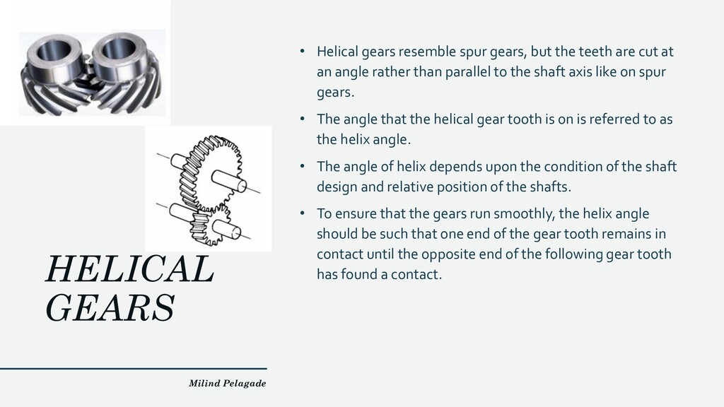
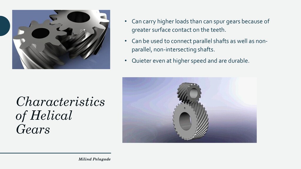
teeth are cut at an angle rather than parallel to the shaft axis like on spur gears. • The angle that the helical gear tooth is on is referred to as the helix angle. • The angle of helix depends upon the condition of the shaft design and relative position of the shafts. • To ensure that the gears run smoothly, the helix angle should be such that one end of the gear tooth remains in contact until the opposite end of the following gear tooth has found a contact. Milind Pelagade 25
can spur gears because of greater surface contact on the teeth. • Can be used to connect parallel shafts as well as non- parallel, non-intersecting shafts. • Quieter even at higher speed and are durable. Milind Pelagade 26
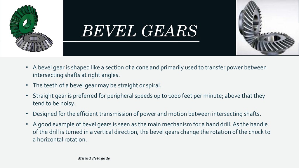
section of a cone and primarily used to transfer power between intersecting shafts at right angles. • The teeth of a bevel gear may be straight or spiral. • Straight gear is preferred for peripheral speeds up to 1000 feet per minute; above that they tend to be noisy. • Designed for the efficient transmission of power and motion between intersecting shafts. • A good example of bevel gears is seen as the main mechanism for a hand drill. As the handle of the drill is turned in a vertical direction, the bevel gears change the rotation of the chuck to a horizontal rotation. Milind Pelagade 27
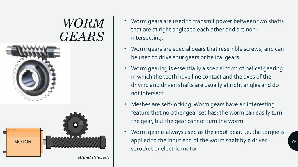
between two shafts that are at right angles to each other and are non- intersecting. • Worm gears are special gears that resemble screws, and can be used to drive spur gears or helical gears. • Worm gearing is essentially a special form of helical gearing in which the teeth have line contact and the axes of the driving and driven shafts are usually at right angles and do not intersect. • Meshes are self-locking. Worm gears have an interesting feature that no other gear set has: the worm can easily turn the gear, but the gear cannot turn the worm. • Worm gear is always used as the input gear, i.e. the torque is applied to the input end of the worm shaft by a driven sprocket or electric motor Milind Pelagade 28
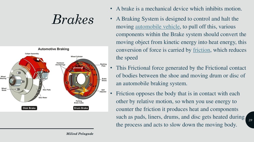
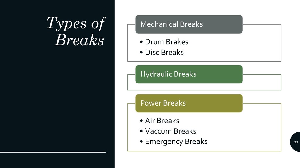
motion. • A Braking System is designed to control and halt the moving automobile vehicle, to pull off this, various components within the Brake system should convert the moving object from kinetic energy into heat energy, this conversion of force is carried by friction, which reduces the speed • This Frictional force generated by the Frictional contact of bodies between the shoe and moving drum or disc of an automobile braking system. • Friction opposes the body that is in contact with each other by relative motion, so when you use energy to counter the friction it produces heat and components such as pads, liners, drums, and disc gets heated during the process and acts to slow down the moving body. Milind Pelagade 29
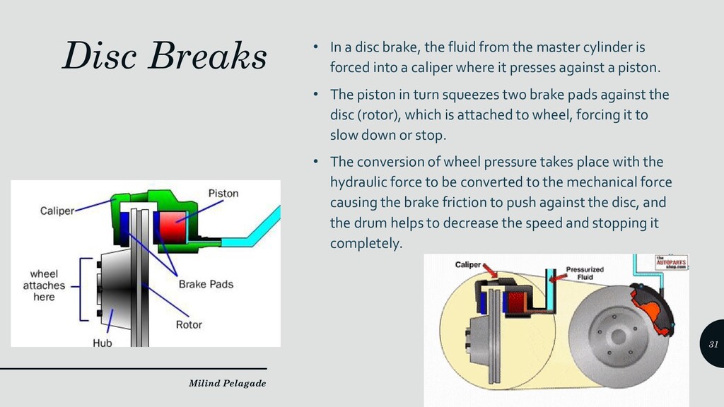
the master cylinder is forced into a caliper where it presses against a piston. • The piston in turn squeezes two brake pads against the disc (rotor), which is attached to wheel, forcing it to slow down or stop. • The conversion of wheel pressure takes place with the hydraulic force to be converted to the mechanical force causing the brake friction to push against the disc, and the drum helps to decrease the speed and stopping it completely. Milind Pelagade 31
(brake torque) to stop the vehicle compared to drum brakes. • It generates less heat compared to drum brakes for the same brake torque. • Ease of maintenance as disk brake is outside the wheel rim. • It cools down faster. • In drum brakes, if worn out brake shoes are not changed at proper time they can damage the drums however, disk brakes do not have such problems. • It is less likely to skid compare to drum brakes in wet condition (when applied with caution). • It is safer than drum brakes under hard braking conditions. • It has brake pad wear indicator which is not present in drum brakes. Milind Pelagade 32
skills required to operate disk brakes. That is the reason why some people are still not comfortable with disk brakes. • If any air remains in disk brake system, it can be problematic as brakes may not work effectively. • Disk brake assembly has more moving parts and it is more complex than drum brakes. • It requires lot of efforts in maintenance like brake fluid (bleeding), change of brake pads etc. Milind Pelagade 33
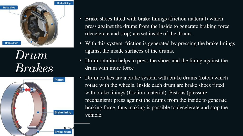
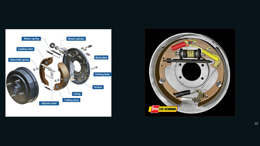
material) which press against the drums from the inside to generate braking force (decelerate and stop) are set inside of the drums. • With this system, friction is generated by pressing the brake linings against the inside surfaces of the drums. • Drum rotation helps to press the shoes and the lining against the drum with more force • Drum brakes are a brake system with brake drums (rotor) which rotate with the wheels. Inside each drum are brake shoes fitted with brake linings (friction material). Pistons (pressure mechanism) press against the drums from the inside to generate braking force, thus making is possible to decelerate and stop the vehicle. Milind Pelagade 34
braking force than an equal diameter disc brake. • Drum brakes last longer because drum brakes have increased friction contact area than a disc. • Drum brakes are cheaper to manufacture than disc brakes. • Rear drum brakes generate lower heat. • Drum brakes have a built-in self energizing effect that requires less input force (such as hydraulic pressure • Wheel cylinders are simpler to recondition than with disc brake calipers. • Brake shoes can be remanufactured for future use. Milind Pelagade 36
to heavy braking, which then can cause the drum to distort, and thus cause vibration under braking. • Brake shoes can overheat to the point where they become glazed. • Excessive brake drum heating can cause the brake fluid to vaporize. • Another disadvantage of drum brakes is their relative complexity. • Maintenance of drum brakes is more time- consuming, compared to disc brakes. Milind Pelagade 37