Upgrade to Pro — share decks privately, control downloads, hide ads and more …

Marie Chabert - Periodic Non-Uniform Sampling (PNS) for Satellite Communications

SCEE Team
December 10, 2015

Marie Chabert - Periodic Non-Uniform Sampling (PNS) for Satellite Communications

SCEE Team

December 10, 2015
Tweet

More Decks by SCEE Team

Other Decks in Research

Transcript

  1. Periodic Non-Uniform Sampling (PNS)
    for Satellite Communications
    Marie Chabert1, Bernard Lacaze2, Marie-Laure Boucheret1,
    Jean-Adrien Vernhes1,2,3,4
    1Universit´
    e de Toulouse, IRIT-ENSEEIHT 2T´
    eSA laboratory
    3CNES (French Spatial Agency) 4Thales Alenia Space
    [email protected]

    View Slide

  2. Introduction The PNS solution Improved PNS PNS delay estimation Conclusion
    Outline
    1 Introduction
    Problem formulation
    Proposed approach
    2 The PNS solution
    Signal model
    Sampling frequency requirements
    PNS sampling scheme and reconstruction formulas
    Practical sampling device: the TI-ADCs
    3 Improved PNS
    Principle
    Convergence speed improvement
    Selective reconstruction with interference cancelation
    Analytic signal reconstruction
    4 PNS delay estimation
    PNS delay estimation with a learning sequence
    Blind PNS delay estimation
    5 Conclusion
    Marie Chabert IRIT-ENSEEIHT – T´
    eSA – CNES – TAS
    Periodic Non-Uniform Sampling (PNS) for Satellite Communications 2 / 44

    View Slide

  3. Introduction The PNS solution Improved PNS PNS delay estimation Conclusion
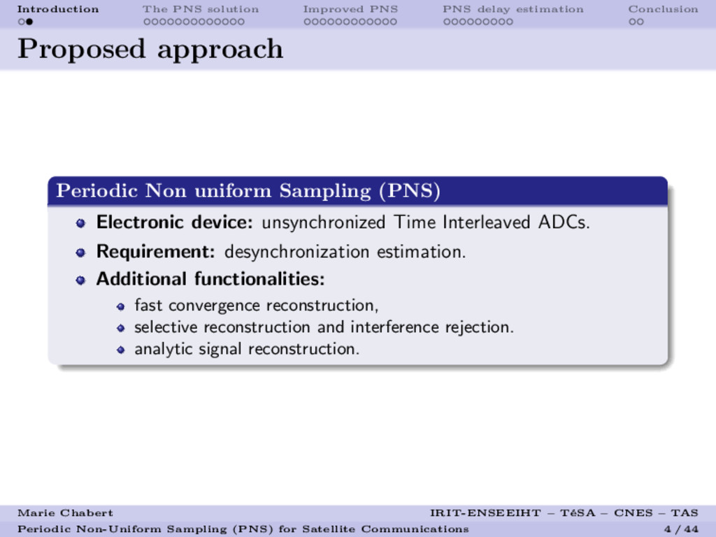
    Problem formulation
    Satellite Communication Context
    Context: increasing frequency bandwidth in satellite
    communications.
    Technical challenge: onboard high-rate analog-to-digital
    conversion.
    Economical and ecological constraints: cost, complexity, weight
    and power consumption of electronic devices.
    Trend: migration of signal processing from analog to digital world.
    Marie Chabert IRIT-ENSEEIHT – T´
    eSA – CNES – TAS
    Periodic Non-Uniform Sampling (PNS) for Satellite Communications 3 / 44

    View Slide

  4. Introduction The PNS solution Improved PNS PNS delay estimation Conclusion
    Proposed approach
    Periodic Non uniform Sampling (PNS)
    Electronic device: unsynchronized Time Interleaved ADCs.
    Requirement: desynchronization estimation.
    Additional functionalities:
    fast convergence reconstruction,
    selective reconstruction and interference rejection.
    analytic signal reconstruction.
    Marie Chabert IRIT-ENSEEIHT – T´
    eSA – CNES – TAS
    Periodic Non-Uniform Sampling (PNS) for Satellite Communications 4 / 44

    View Slide

  5. Introduction The PNS solution Improved PNS PNS delay estimation Conclusion
    Outline
    1 Introduction
    Problem formulation
    Proposed approach
    2 The PNS solution
    Signal model
    Sampling frequency requirements
    PNS sampling scheme and reconstruction formulas
    Practical sampling device: the TI-ADCs
    3 Improved PNS
    Principle
    Convergence speed improvement
    Selective reconstruction with interference cancelation
    Analytic signal reconstruction
    4 PNS delay estimation
    PNS delay estimation with a learning sequence
    Blind PNS delay estimation
    5 Conclusion
    Marie Chabert IRIT-ENSEEIHT – T´
    eSA – CNES – TAS
    Periodic Non-Uniform Sampling (PNS) for Satellite Communications 5 / 44

    View Slide

  6. Introduction The PNS solution Improved PNS PNS delay estimation Conclusion
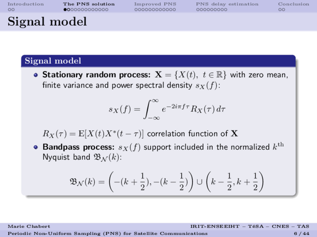
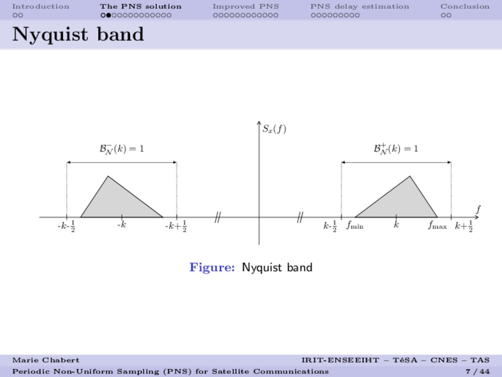
    Signal model
    Signal model
    Stationary random process: X = {X(t), t ∈ R} with zero mean,
    finite variance and power spectral density sX
    (f):
    sX
    (f) =

    −∞
    e−2iπfτ RX
    (τ) dτ
    RX
    (τ) = E[X(t)X∗(t − τ)] correlation function of X
    Bandpass process: sX
    (f) support included in the normalized kth
    Nyquist band BN
    (k):
    BN
    (k) = −(k +
    1
    2
    ), −(k −
    1
    2
    ) ∪ k −
    1
    2
    , k +
    1
    2
    Marie Chabert IRIT-ENSEEIHT – T´
    eSA – CNES – TAS
    Periodic Non-Uniform Sampling (PNS) for Satellite Communications 6 / 44

    View Slide

  7. Introduction The PNS solution Improved PNS PNS delay estimation Conclusion
    Nyquist band
    Sx
    (f)
    f
    k-1
    2
    k k+1
    2
    fmin
    fmax
    -k+1
    2
    -k
    -k-1
    2
    B+
    N
    (k) = 1
    B−
    N
    (k) = 1
    Figure: Nyquist band
    Marie Chabert IRIT-ENSEEIHT – T´
    eSA – CNES – TAS
    Periodic Non-Uniform Sampling (PNS) for Satellite Communications 7 / 44

    View Slide

  8. Introduction The PNS solution Improved PNS PNS delay estimation Conclusion
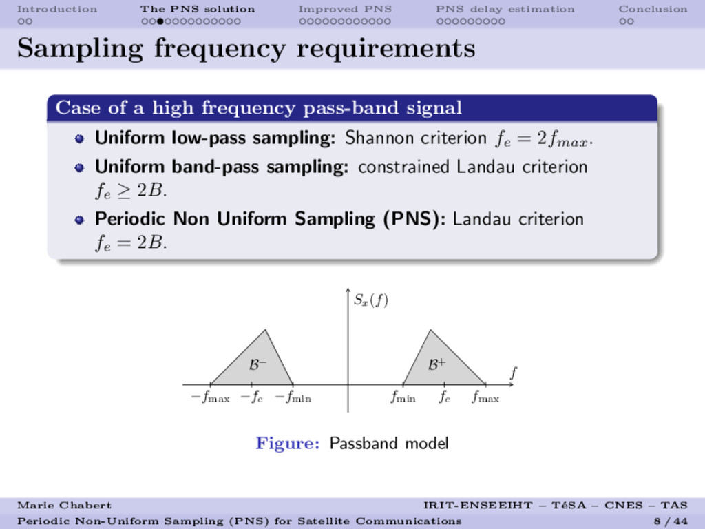
    Sampling frequency requirements
    Case of a high frequency pass-band signal
    Uniform low-pass sampling: Shannon criterion fe
    = 2fmax.
    Uniform band-pass sampling: constrained Landau criterion
    fe
    ≥ 2B.
    Periodic Non Uniform Sampling (PNS): Landau criterion
    fe
    = 2B.
    Sx
    (f)
    f
    B− B+
    −fc
    fc
    −fmax
    fmax
    −fmin
    fmin
    Figure: Passband model
    Marie Chabert IRIT-ENSEEIHT – T´
    eSA – CNES – TAS
    Periodic Non-Uniform Sampling (PNS) for Satellite Communications 8 / 44

    View Slide

  9. Introduction The PNS solution Improved PNS PNS delay estimation Conclusion
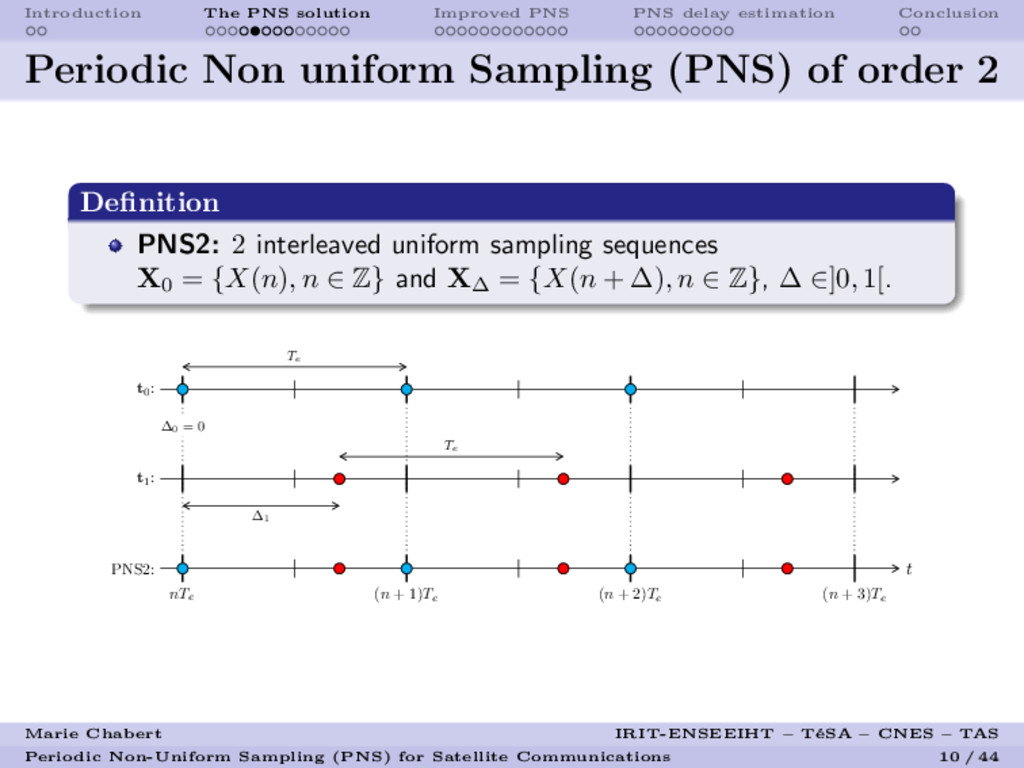
    Periodic Non uniform Sampling (PNS) of order
    L
    Definition
    PNSL: L interleaved uniform sampling sequences
    Xi
    = {X(n + δi
    ), n ∈ Z}, δi
    ∈]0, 1[, i ∈ {0, L}.
    t
    nTe (n + 1)Te
    (n + 2)Te
    (n + 3)Te
    PNSL:
    tL−1
    :
    · · ·
    t2
    :
    t1
    :
    t0
    :
    ∆0
    Te
    ∆1
    Te
    ∆2
    Te
    ∆L−1
    Te
    Marie Chabert IRIT-ENSEEIHT – T´
    eSA – CNES – TAS
    Periodic Non-Uniform Sampling (PNS) for Satellite Communications 9 / 44

    View Slide

  10. Introduction The PNS solution Improved PNS PNS delay estimation Conclusion
    Periodic Non uniform Sampling (PNS) of order 2
    Definition
    PNS2: 2 interleaved uniform sampling sequences
    X0
    = {X(n), n ∈ Z} and X∆
    = {X(n + ∆), n ∈ Z}, ∆ ∈]0, 1[.
    t
    nTe (n + 1)Te
    (n + 2)Te
    (n + 3)Te
    PNS2:
    t1
    :
    t0
    :
    ∆0
    = 0
    Te
    ∆1
    Te
    Marie Chabert IRIT-ENSEEIHT – T´
    eSA – CNES – TAS
    Periodic Non-Uniform Sampling (PNS) for Satellite Communications 10 / 44

    View Slide

  11. Introduction The PNS solution Improved PNS PNS delay estimation Conclusion
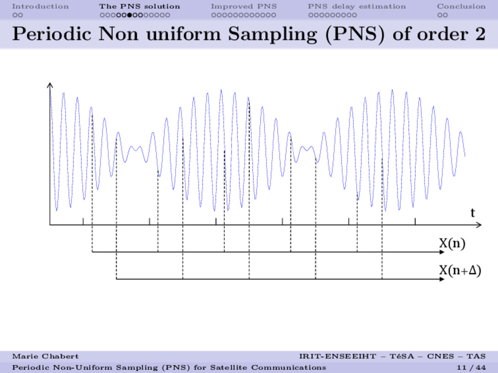
    Periodic Non uniform Sampling (PNS) of order 2
    X(n)
    t
    X(n+Δ)
    Marie Chabert IRIT-ENSEEIHT – T´
    eSA – CNES – TAS
    Periodic Non-Uniform Sampling (PNS) for Satellite Communications 11 / 44

    View Slide

  12. Introduction The PNS solution Improved PNS PNS delay estimation Conclusion
    PNS2 reconstruction - Filter formulation1
    µt
    ψt

    µ∆

    +

    X0
    X∆ D
    ˜
    X0
    ˜
    XK
    ˜
    X
    (a) Orthogonal scheme
    ηt
    ψt

    X0
    X∆
    ˜
    X
    ˜
    X0
    ˜
    X
    K
    (b) Symmetrical scheme
    General filter expressions
    µt
    (f) = St
    (f)
    S0(f)
    e2iπft
    ηt
    (f) = µt
    (f) − µ∆
    (f)ψt
    (f)
    ψt
    (f) = e2iπf(t−∆) S0(f)St−∆(f)−S∗

    (f)St
    (f)
    S2
    0
    (f)−|St−∆(f)|2
    with: Sλ
    (f) =
    n∈Z
    sX
    (f + n)e2iπnλ, f ∈ (−1
    2
    , 1
    2
    )
    1B. Lacaze. “Filtering from PNS2 Sampling”. In: Sampling Theory in Signal and
    Image Processing (STSIP) 11.1 (2012), pp. 43–53.
    Marie Chabert IRIT-ENSEEIHT – T´
    eSA – CNES – TAS
    Periodic Non-Uniform Sampling (PNS) for Satellite Communications 12 / 44

    View Slide

  13. Introduction The PNS solution Improved PNS PNS delay estimation Conclusion
    PNS2 reconstruction - Interpolation formulas2
    Closed-form reconstruction formulas
    Hypothesis: Bandpass signal composed of two sub-bands, no
    oversampling.
    Simple exact PNS2 reconstruction formulas :


    X(t) =
    A0
    (t) sin [2πk(∆ − t)] + A∆
    (t) sin [2πkt]
    sin [2πk∆]
    with Aλ
    (t) =
    n∈Z
    sin [π(t − n − λ)]
    π(t − n − λ)
    X(n + λ)
    if 2k∆ /
    ∈ Z
    2B. Lacaze. “Equivalent circuits for the PNS2 sampling scheme”. In: IEEE
    Transactions on Circuits and Systems I: Regular Papers 57.11 (2010), pp. 2904–2914.
    Marie Chabert IRIT-ENSEEIHT – T´
    eSA – CNES – TAS
    Periodic Non-Uniform Sampling (PNS) for Satellite Communications 13 / 44

    View Slide

  14. Introduction The PNS solution Improved PNS PNS delay estimation Conclusion
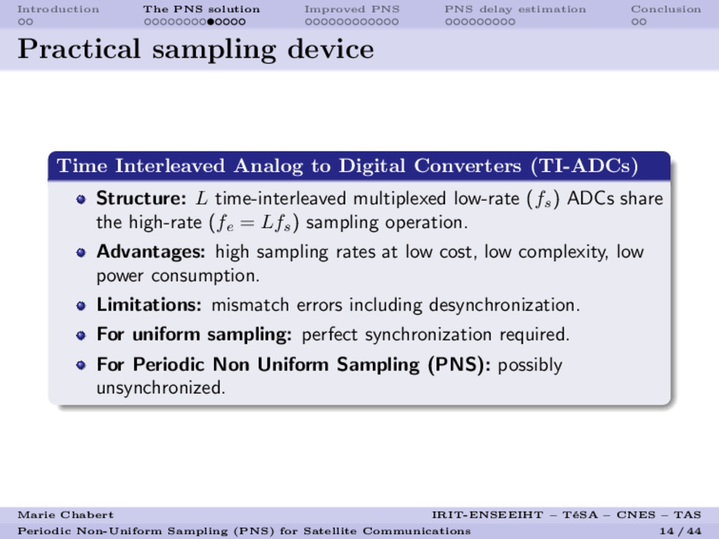
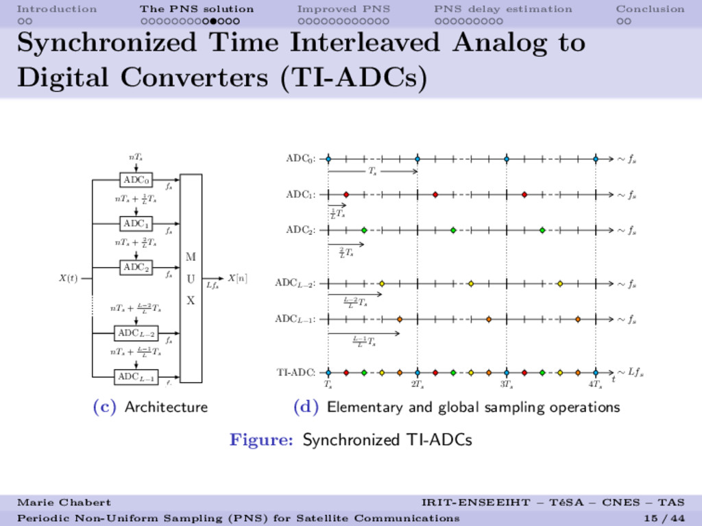
    Practical sampling device
    Time Interleaved Analog to Digital Converters (TI-ADCs)
    Structure: L time-interleaved multiplexed low-rate (fs) ADCs share
    the high-rate (fe
    = Lfs) sampling operation.
    Advantages: high sampling rates at low cost, low complexity, low
    power consumption.
    Limitations: mismatch errors including desynchronization.
    For uniform sampling: perfect synchronization required.
    For Periodic Non Uniform Sampling (PNS): possibly
    unsynchronized.
    Marie Chabert IRIT-ENSEEIHT – T´
    eSA – CNES – TAS
    Periodic Non-Uniform Sampling (PNS) for Satellite Communications 14 / 44

    View Slide

  15. Introduction The PNS solution Improved PNS PNS delay estimation Conclusion
    Synchronized Time Interleaved Analog to
    Digital Converters (TI-ADCs)
    M
    U
    X
    X[n]
    Lfs
    X(t)
    ADCL−1
    nTs
    + L−1
    L
    Ts
    fs
    ADCL−2
    nTs
    + L−2
    L
    Ts
    fs
    ADC2
    nTs
    + 2
    L
    Ts
    fs
    ADC1
    nTs
    + 1
    L
    Ts
    fs
    ADC0
    nTs
    fs
    (c) Architecture
    t
    ∼ Lfs
    Ts
    2Ts
    3Ts
    4Ts
    TI-ADC:
    ADCL−1
    :
    ADCL−2
    :
    ADC2
    :
    ADC1
    :
    ADC0
    :
    ∼ fs
    ∼ fs
    ∼ fs
    ∼ fs
    ∼ fs
    Ts
    1
    L
    Ts
    2
    L
    Ts
    L−2
    L
    Ts
    L−1
    L
    Ts
    (d) Elementary and global sampling operations
    Figure: Synchronized TI-ADCs
    Marie Chabert IRIT-ENSEEIHT – T´
    eSA – CNES – TAS
    Periodic Non-Uniform Sampling (PNS) for Satellite Communications 15 / 44

    View Slide

  16. Introduction The PNS solution Improved PNS PNS delay estimation Conclusion
    Synchronized TI-ADCs: an ideal model
    Synchronization at all price
    Associated sampling scheme: uniform sampling.
    In practice: design imperfections and operating conditions ⇒
    desynchronization.
    Common solution: calibration and hardware corrections.
    Marie Chabert IRIT-ENSEEIHT – T´
    eSA – CNES – TAS
    Periodic Non-Uniform Sampling (PNS) for Satellite Communications 16 / 44

    View Slide

  17. Introduction The PNS solution Improved PNS PNS delay estimation Conclusion
    Unsynchronized TI-ADC
    X[n]
    R
    E
    C
    O
    N
    S
    T
    Lfs
    δi, i = 0, ..., L − 1
    X(t)
    ADCL−1
    nTs
    + δL−1
    fs
    ADCL−2
    nTs
    + δL−2
    fs
    ADC2
    nTs
    + δ2
    fs
    ADC1
    nTs
    + δ1
    fs
    ADC0
    nTs
    + δ0
    fs
    (a) Realistic/desynchronized
    TI-ADC architecture
    t
    ∼ Lfs
    Ts
    2Ts
    3Ts
    4Ts
    TI-ADC:
    ADCL−1
    :
    ADCL−2
    :
    ADC2
    :
    ADC1
    :
    ADC0
    :
    ∼ fs
    ∼ fs
    ∼ fs
    ∼ fs
    ∼ fs
    δ0
    δ1
    δ2
    δL−2
    δL−1
    (b) Elementary and global (non uniform)
    sampling operations
    Figure: Realistic/desynchronized TI-ADC model
    Marie Chabert IRIT-ENSEEIHT – T´
    eSA – CNES – TAS
    Periodic Non-Uniform Sampling (PNS) for Satellite Communications 17 / 44

    View Slide

  18. Introduction The PNS solution Improved PNS PNS delay estimation Conclusion
    Unsynchronized TI-ADCs: a realistic model
    Contributions: ”desynchronization... so?”
    Proposed sampling scheme: Periodic Non uniform Sampling.
    No hardware correction of the desynchronization required.
    Estimation of the desynchronization:
    hypothesis: slow variations of the desynchronization,
    from a training sequence,
    blindly.
    Complexity moved from analog to digital world:
    Digital compensation of the desynchronization.
    Additional functionalities:
    improved reconstruction speed,
    selective reconstruction with interference rejection,
    analytic signal reconstruction.
    Dirty RF paradigm: how to cope with low-cost imperfect analog
    devices thanks to subsequent digital processing.
    Marie Chabert IRIT-ENSEEIHT – T´
    eSA – CNES – TAS
    Periodic Non-Uniform Sampling (PNS) for Satellite Communications 18 / 44

    View Slide

  19. Introduction The PNS solution Improved PNS PNS delay estimation Conclusion
    Outline
    1 Introduction
    Problem formulation
    Proposed approach
    2 The PNS solution
    Signal model
    Sampling frequency requirements
    PNS sampling scheme and reconstruction formulas
    Practical sampling device: the TI-ADCs
    3 Improved PNS
    Principle
    Convergence speed improvement
    Selective reconstruction with interference cancelation
    Analytic signal reconstruction
    4 PNS delay estimation
    PNS delay estimation with a learning sequence
    Blind PNS delay estimation
    5 Conclusion
    Marie Chabert IRIT-ENSEEIHT – T´
    eSA – CNES – TAS
    Periodic Non-Uniform Sampling (PNS) for Satellite Communications 19 / 44

    View Slide

  20. Introduction The PNS solution Improved PNS PNS delay estimation Conclusion
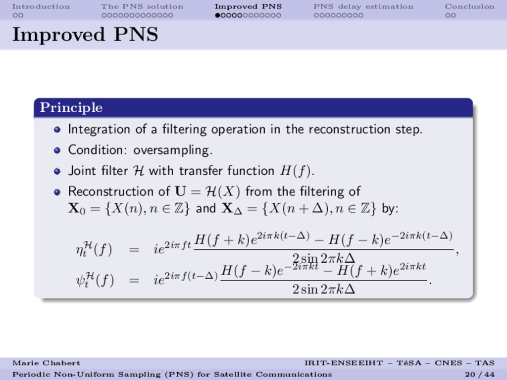
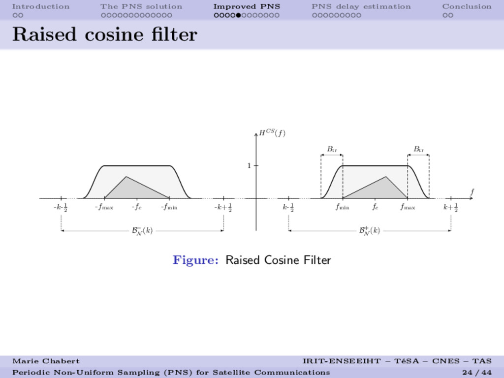
    Improved PNS
    Principle
    Integration of a filtering operation in the reconstruction step.
    Condition: oversampling.
    Joint filter H with transfer function H(f).
    Reconstruction of U = H(X) from the filtering of
    X0
    = {X(n), n ∈ Z} and X∆
    = {X(n + ∆), n ∈ Z} by:
    ηH
    t
    (f) = ie2iπft
    H(f + k)e2iπk(t−∆) − H(f − k)e−2iπk(t−∆)
    2 sin 2πk∆
    ,
    ψH
    t
    (f) = ie2iπf(t−∆)
    H(f − k)e−2iπkt − H(f + k)e2iπkt
    2 sin 2πk∆
    .
    Marie Chabert IRIT-ENSEEIHT – T´
    eSA – CNES – TAS
    Periodic Non-Uniform Sampling (PNS) for Satellite Communications 20 / 44

    View Slide

  21. Introduction The PNS solution Improved PNS PNS delay estimation Conclusion
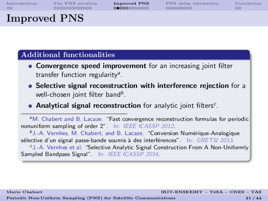
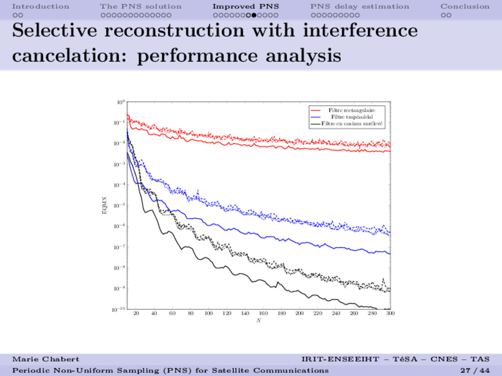
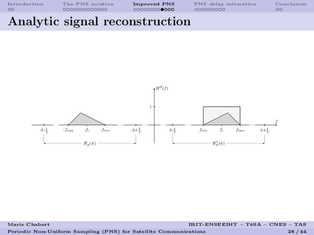
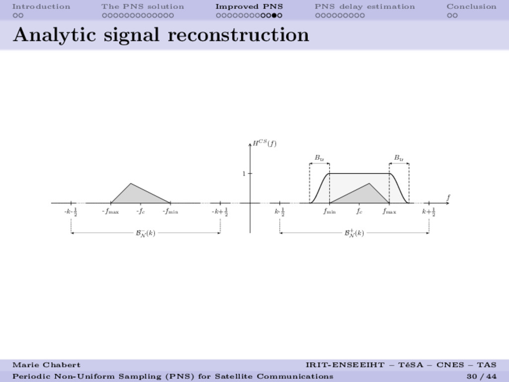
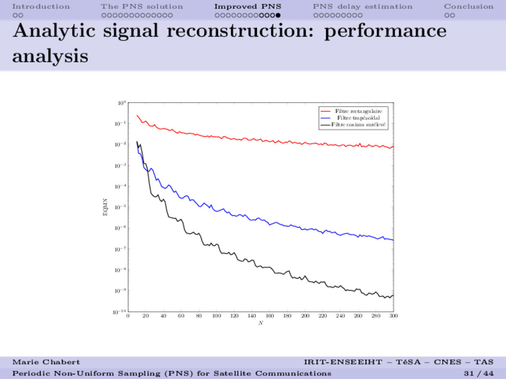
    Improved PNS
    Additional functionalities
    Convergence speed improvement for an increasing joint filter
    transfer function regularitya.
    Selective signal reconstruction with interference rejection for a
    well-chosen joint filter bandb.
    Analytical signal reconstruction for analytic joint filtersc.
    aM. Chabert and B. Lacaze. “Fast convergence reconstruction formulas for periodic
    nonuniform sampling of order 2”. In: IEEE ICASSP 2012.
    bJ.-A. Vernhes, M. Chabert, and B. Lacaze. “Conversion Num´
    erique-Analogique

    elective d’un signal passe-bande soumis `
    a des interf´
    erences”. In: GRETSI 2013.
    cJ.-A. Vernhes et al. “Selective Analytic Signal Construction From A Non-Uniformly
    Sampled Bandpass Signal”. In: IEEE ICASSP 2014.
    Marie Chabert IRIT-ENSEEIHT – T´
    eSA – CNES – TAS
    Periodic Non-Uniform Sampling (PNS) for Satellite Communications 21 / 44

    View Slide

  22. Introduction The PNS solution Improved PNS PNS delay estimation Conclusion
    Rectangular filter
    HR(f)
    f
    1
    fc
    fmin
    fmax
    -fc
    -fmin
    -fmax
    B+
    N
    (k)
    B−
    N
    (k)
    k-1
    2
    k+1
    2
    -k+1
    2
    -k-1
    2
    Figure: Rectangular filter
    Marie Chabert IRIT-ENSEEIHT – T´
    eSA – CNES – TAS
    Periodic Non-Uniform Sampling (PNS) for Satellite Communications 22 / 44

    View Slide

  23. Introduction The PNS solution Improved PNS PNS delay estimation Conclusion
    Trapezoidal filter
    HT (f)
    f
    1
    fc
    Btr
    Btr
    fmin
    fmax
    -fc
    -fmin
    -fmax
    B+
    N
    (k)
    B−
    N
    (k)
    k-1
    2
    k+1
    2
    -k+1
    2
    -k-1
    2
    Figure: Trapezoidal filter
    Marie Chabert IRIT-ENSEEIHT – T´
    eSA – CNES – TAS
    Periodic Non-Uniform Sampling (PNS) for Satellite Communications 23 / 44

    View Slide

  24. Introduction The PNS solution Improved PNS PNS delay estimation Conclusion
    Raised cosine filter
    HCS(f)
    f
    1
    fc
    Btr
    Btr
    fmin
    fmax
    -fc
    -fmin
    -fmax
    B+
    N
    (k)
    B−
    N
    (k)
    k-1
    2
    k+1
    2
    -k+1
    2
    -k-1
    2
    Figure: Raised Cosine Filter
    Marie Chabert IRIT-ENSEEIHT – T´
    eSA – CNES – TAS
    Periodic Non-Uniform Sampling (PNS) for Satellite Communications 24 / 44

    View Slide

  25. Introduction The PNS solution Improved PNS PNS delay estimation Conclusion
    Convergence speed improvement: performance
    analysis
    20 40 60 80 100 120 140 160 180 200 220 240 260 280 300
    10−12
    10−11
    10−10
    10−9
    10−8
    10−7
    10−6
    10−5
    10−4
    10−3
    10−2
    N
    EQMN
    Filtre rectangulaire
    Filtre trap´
    ezo¨
    ıdal
    Filtre en cosinus sur´
    elev´
    e
    Marie Chabert IRIT-ENSEEIHT – T´
    eSA – CNES – TAS
    Periodic Non-Uniform Sampling (PNS) for Satellite Communications 25 / 44

    View Slide

  26. Introduction The PNS solution Improved PNS PNS delay estimation Conclusion
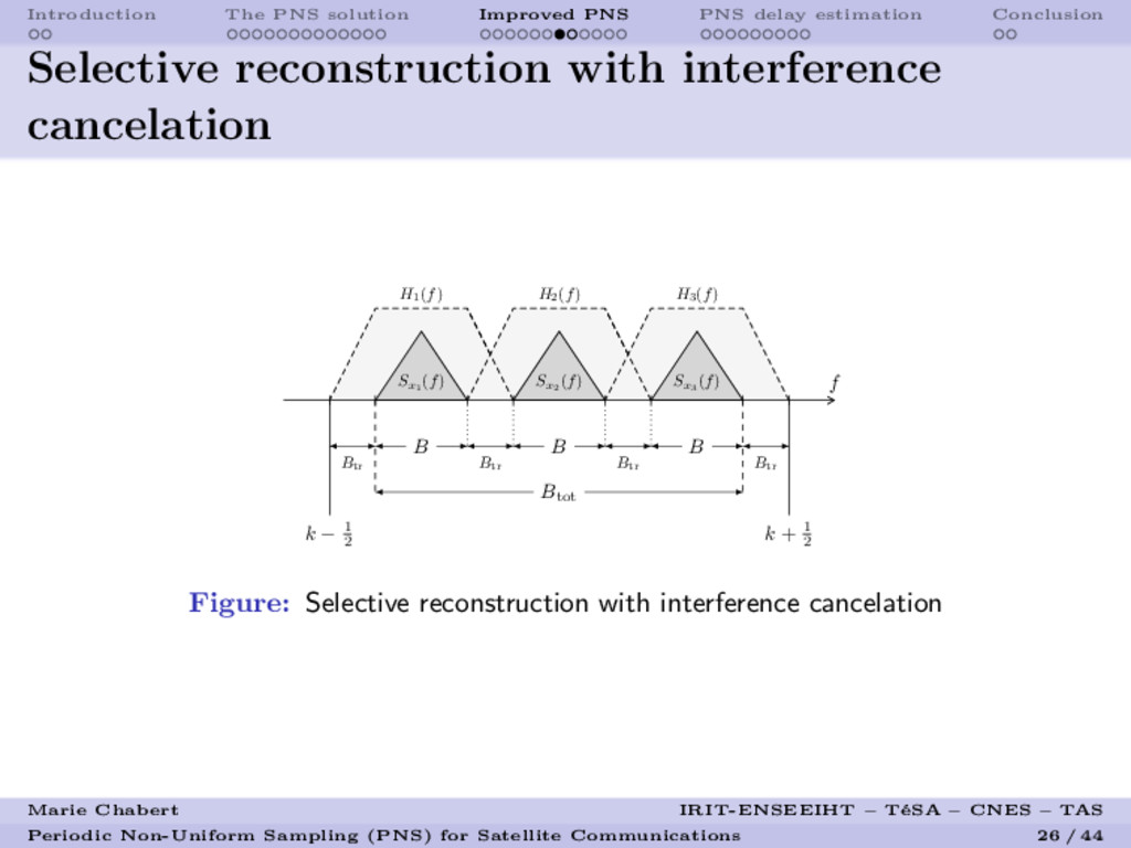
    Selective reconstruction with interference
    cancelation
    f
    k + 1
    2
    k − 1
    2
    Btot
    Sx1
    (f) Sx2
    (f) Sx3
    (f)
    B B B
    Btr
    Btr
    Btr
    Btr
    H1
    (f) H2
    (f) H3
    (f)
    Figure: Selective reconstruction with interference cancelation
    Marie Chabert IRIT-ENSEEIHT – T´
    eSA – CNES – TAS
    Periodic Non-Uniform Sampling (PNS) for Satellite Communications 26 / 44

    View Slide

  27. Introduction The PNS solution Improved PNS PNS delay estimation Conclusion
    Selective reconstruction with interference
    cancelation: performance analysis
    20 40 60 80 100 120 140 160 180 200 220 240 260 280 300
    10−10
    10−9
    10−8
    10−7
    10−6
    10−5
    10−4
    10−3
    10−2
    10−1
    100
    N
    EQMN
    Filtre rectangulaire
    Filtre trap´
    ezo¨
    ıdal
    Filtre en cosinus sur´
    elev´
    e
    Marie Chabert IRIT-ENSEEIHT – T´
    eSA – CNES – TAS
    Periodic Non-Uniform Sampling (PNS) for Satellite Communications 27 / 44

    View Slide

  28. Introduction The PNS solution Improved PNS PNS delay estimation Conclusion
    Analytic signal reconstruction
    HR(f)
    f
    1
    fc
    fmin
    fmax
    -fc
    -fmin
    -fmax
    B+
    N
    (k)
    B−
    N
    (k)
    k-1
    2
    k+1
    2
    -k+1
    2
    -k-1
    2
    Marie Chabert IRIT-ENSEEIHT – T´
    eSA – CNES – TAS
    Periodic Non-Uniform Sampling (PNS) for Satellite Communications 28 / 44

    View Slide

  29. Introduction The PNS solution Improved PNS PNS delay estimation Conclusion
    Analytic signal reconstruction
    HT (f)
    f
    1
    fc
    Btr
    Btr
    fmin
    fmax
    -fc
    -fmin
    -fmax
    B+
    N
    (k)
    B−
    N
    (k)
    k-1
    2
    k+1
    2
    -k+1
    2
    -k-1
    2
    Marie Chabert IRIT-ENSEEIHT – T´
    eSA – CNES – TAS
    Periodic Non-Uniform Sampling (PNS) for Satellite Communications 29 / 44

    View Slide

  30. Introduction The PNS solution Improved PNS PNS delay estimation Conclusion
    Analytic signal reconstruction
    HCS(f)
    f
    1
    fc
    Btr
    Btr
    fmin
    fmax
    -fc
    -fmin
    -fmax
    B+
    N
    (k)
    B−
    N
    (k)
    k-1
    2
    k+1
    2
    -k+1
    2
    -k-1
    2
    Marie Chabert IRIT-ENSEEIHT – T´
    eSA – CNES – TAS
    Periodic Non-Uniform Sampling (PNS) for Satellite Communications 30 / 44

    View Slide

  31. Introduction The PNS solution Improved PNS PNS delay estimation Conclusion
    Analytic signal reconstruction: performance
    analysis
    0 20 40 60 80 100 120 140 160 180 200 220 240 260 280 300
    10−10
    10−9
    10−8
    10−7
    10−6
    10−5
    10−4
    10−3
    10−2
    10−1
    100
    N
    EQMN
    Filtre rectangulaire
    Filtre trap´
    ezo¨
    ıdal
    Filtre cosinus sur´
    elev´
    e
    Marie Chabert IRIT-ENSEEIHT – T´
    eSA – CNES – TAS
    Periodic Non-Uniform Sampling (PNS) for Satellite Communications 31 / 44

    View Slide

  32. Introduction The PNS solution Improved PNS PNS delay estimation Conclusion
    Outline
    1 Introduction
    Problem formulation
    Proposed approach
    2 The PNS solution
    Signal model
    Sampling frequency requirements
    PNS sampling scheme and reconstruction formulas
    Practical sampling device: the TI-ADCs
    3 Improved PNS
    Principle
    Convergence speed improvement
    Selective reconstruction with interference cancelation
    Analytic signal reconstruction
    4 PNS delay estimation
    PNS delay estimation with a learning sequence
    Blind PNS delay estimation
    5 Conclusion
    Marie Chabert IRIT-ENSEEIHT – T´
    eSA – CNES – TAS
    Periodic Non-Uniform Sampling (PNS) for Satellite Communications 32 / 44

    View Slide

  33. Introduction The PNS solution Improved PNS PNS delay estimation Conclusion
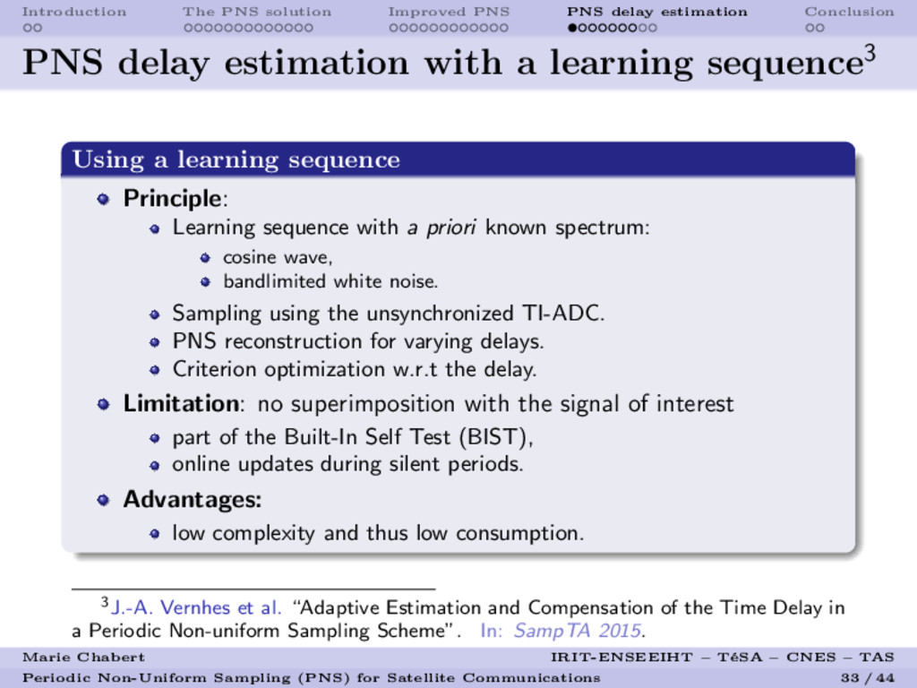
    PNS delay estimation with a learning sequence3
    Using a learning sequence
    Principle:
    Learning sequence with a priori known spectrum:
    cosine wave,
    bandlimited white noise.
    Sampling using the unsynchronized TI-ADC.
    PNS reconstruction for varying delays.
    Criterion optimization w.r.t the delay.
    Limitation: no superimposition with the signal of interest
    part of the Built-In Self Test (BIST),
    online updates during silent periods.
    Advantages:
    low complexity and thus low consumption.
    3J.-A. Vernhes et al. “Adaptive Estimation and Compensation of the Time Delay in
    a Periodic Non-uniform Sampling Scheme”. In: SampTA 2015.
    Marie Chabert IRIT-ENSEEIHT – T´
    eSA – CNES – TAS
    Periodic Non-Uniform Sampling (PNS) for Satellite Communications 33 / 44

    View Slide

  34. Introduction The PNS solution Improved PNS PNS delay estimation Conclusion
    Principle: orthogonality property
    Known delay: orthogonal equivalent scheme
    Orthogonality between D = {D(n), n ∈ Z} and X0
    = {X(n), n ∈ Z}:
    E[D(n)X∗
    0
    (m)] = 0 , ∀(n, m) ∈ Z
    with:
    D(n) = X(n + ∆) − µ∆
    [X0
    ](n)
    µt
    ψt

    µ∆

    +

    X0
    X∆ D
    ˜
    X0
    ˜
    XK
    ˜
    X
    Marie Chabert IRIT-ENSEEIHT – T´
    eSA – CNES – TAS
    Periodic Non-Uniform Sampling (PNS) for Satellite Communications 34 / 44

    View Slide

  35. Introduction The PNS solution Improved PNS PNS delay estimation Conclusion
    Principle: orthogonality property
    Unknown delay: loss of orthogonality
    Sampling sequences: X0
    , X∆.
    Reconstruction using a wrong delay ∆ ∈]0, 1[, ∆ = ∆.
    Loss of orthogonality criterion:
    σ2

    = E |X(n + ∆) − µ

    [X0
    ](n)|2
    =

    −∞
    e2iπf∆ − µ

    (f) 2
    sX
    (f) df
    For simplificity:
    Baseband learning sequence: sX
    (f) = 0 for f /
    ∈ −1
    2
    , 1
    2
    Delay filter µ

    (f): µ

    [X0
    ](n) = X(n + ∆)
    Marie Chabert IRIT-ENSEEIHT – T´
    eSA – CNES – TAS
    Periodic Non-Uniform Sampling (PNS) for Satellite Communications 35 / 44

    View Slide

  36. Introduction The PNS solution Improved PNS PNS delay estimation Conclusion
    Principle: orthogonality property
    Unknown delay: loss of orthogonality
    Simplified criterion closed-form expression:
    σ2

    = E |X(n + ∆) − X(n + ∆)|2
    = 1
    2
    − 1
    2
    e2iπf(∆−∆) − 1
    2
    sX
    (f) df
    with:
    µ

    [X0
    ](n) = X(n + ∆) =
    k
    sin[π(∆ − k)]
    π(∆ − k)
    X(n + k)
    Comparison between closed-form expression and empirical
    estimation for particular learning sequences ⇒ ∆ estimation.
    Marie Chabert IRIT-ENSEEIHT – T´
    eSA – CNES – TAS
    Periodic Non-Uniform Sampling (PNS) for Satellite Communications 36 / 44

    View Slide

  37. Introduction The PNS solution Improved PNS PNS delay estimation Conclusion
    Examples of learning sequences
    Cosine wave
    Learning sequence: Cosine wave at frequency f0 defined by
    sX
    (f) =
    1
    2
    (δ(f − f0
    ) + δ(f + f0
    )) , −
    1
    2
    < f0
    <
    1
    2
    Criterion closed-form expression:
    σ2

    = 4 sin2 πf0
    (∆ − ∆)
    Estimation of ∆:
    ˆ
    ∆ = ∆ −
    1
    2πf0
    arccos 1 −
    σ2

    2
    Marie Chabert IRIT-ENSEEIHT – T´
    eSA – CNES – TAS
    Periodic Non-Uniform Sampling (PNS) for Satellite Communications 37 / 44

    View Slide

  38. Introduction The PNS solution Improved PNS PNS delay estimation Conclusion
    Learning sequence example 2
    Bandlimited white noise
    Learning sequence: bandlimited white noise defined by
    sX
    (f) =
    1 on (−1
    2
    + ε, 1
    2
    − ε) , 0 < ε < 1
    2
    0 elsewhere
    Criterion closed-form expression:
    σ2

    ≈ 1
    2
    −ε
    − 1
    2

    e2iπf(∆−∆) − 1
    2
    df
    ≈ 2(1 − 2ε) 1 − sinc[π(∆ − ∆)(1 − 2ε)]
    Estimation of ∆ from:
    sinc[π(∆ − ∆)(1 − 2ε)] = 1 −
    σ2

    2(1 − 2ε)
    Marie Chabert IRIT-ENSEEIHT – T´
    eSA – CNES – TAS
    Periodic Non-Uniform Sampling (PNS) for Satellite Communications 38 / 44

    View Slide

  39. Introduction The PNS solution Improved PNS PNS delay estimation Conclusion
    Performance analysis
    0 0.1 0.2 0.3 0.4 0.5 0.6 0.7 0.8 0.9 1
    ·104
    10−8
    10−7
    10−6
    10−5
    N
    E | ˆ
    ∆ − ∆|2
    Marie Chabert IRIT-ENSEEIHT – T´
    eSA – CNES – TAS
    Periodic Non-Uniform Sampling (PNS) for Satellite Communications 39 / 44

    View Slide

  40. Introduction The PNS solution Improved PNS PNS delay estimation Conclusion
    Blind PNS delay estimation4
    Principle: stationarity property
    Property: wide sense stationarity of the reconstructed signal
    X( ˜
    ∆) = {X( ˜
    ∆)(t), t ∈ R} if and only if ˜
    ∆ = ∆. In particular:
    P( ˜
    ∆)(tm
    ) = E X( ˜
    ∆) (tm
    )
    2
    , tm
    =
    m
    M + 1
    , m = 1, ..., M
    independent of tm.
    Strategy: estimation of the reconstructed signal power P( ˜
    ∆)(tm
    )
    for m = 1, ..., M for different values of ˜
    ∆:
    P( ˜
    ∆)(tm
    ) =
    1
    N
    N
    2
    n=− N
    2
    X( ˜
    ∆) (n + tm
    )
    2
    , m = 1, ..., M.
    4J.-A. Vernhes et al. “Estimation du retard en ´
    echantillonnage p´
    eriodique non
    uniforme - Application aux CAN entrelac´
    es d´
    esynchronis´
    es”. In: GRETSI 2015.
    Marie Chabert IRIT-ENSEEIHT – T´
    eSA – CNES – TAS
    Periodic Non-Uniform Sampling (PNS) for Satellite Communications 40 / 44

    View Slide

  41. Introduction The PNS solution Improved PNS PNS delay estimation Conclusion
    Performance analysis
    0.17 0.18 0.19 0.2 0.21 ∆ 0.24 0.25 0.26 0.27 0.28 0.29 0.3 0.31 0.32 0.33
    10−1
    100
    101
    102
    103
    ˜

    P( ˜
    ∆)
    m
    (a) Estimated power at different
    times tm
    0.17 0.18 0.19 0.2 0.21 ∆ 0.24 0.25 0.26 0.27 0.28 0.29 0.3 0.31 0.32 0.33
    10−4
    10−3
    10−2
    10−1
    100
    101
    102
    103
    104
    105
    ˜

    (b) Variance of the estimated
    power
    Figure: Blind estimation principle
    Marie Chabert IRIT-ENSEEIHT – T´
    eSA – CNES – TAS
    Periodic Non-Uniform Sampling (PNS) for Satellite Communications 41 / 44

    View Slide

  42. Introduction The PNS solution Improved PNS PNS delay estimation Conclusion
    Outline
    1 Introduction
    Problem formulation
    Proposed approach
    2 The PNS solution
    Signal model
    Sampling frequency requirements
    PNS sampling scheme and reconstruction formulas
    Practical sampling device: the TI-ADCs
    3 Improved PNS
    Principle
    Convergence speed improvement
    Selective reconstruction with interference cancelation
    Analytic signal reconstruction
    4 PNS delay estimation
    PNS delay estimation with a learning sequence
    Blind PNS delay estimation
    5 Conclusion
    Marie Chabert IRIT-ENSEEIHT – T´
    eSA – CNES – TAS
    Periodic Non-Uniform Sampling (PNS) for Satellite Communications 42 / 44

    View Slide

  43. Introduction The PNS solution Improved PNS PNS delay estimation Conclusion
    Conclusion
    Contributions
    PNS as an alternative sampling scheme proposed for TI-ADCs.
    Additional functionalities for telecommunications:
    improved convergence speeda,
    selective reconstruction with interference rejectionb,
    analytical signal reconstructionc.
    Estimation of the desynchronisation:
    from a learning sequenced, blindlye.
    aM. Chabert and B. Lacaze. “Fast convergence reconstruction formulas for periodic
    nonuniform sampling of order 2”. In: IEEE ICASSP 2012.
    bJ.-A. Vernhes, M. Chabert, and B. Lacaze. “Conversion Num´
    erique-Analogique

    elective d’un signal passe-bande soumis `
    a des interf´
    erences”. In: GRETSI 2013.
    cJ.-A. Vernhes et al. “Selective Analytic Signal Construction From A Non-Uniformly
    Sampled Bandpass Signal”. In: IEEE ICASSP 2014.
    dJ.-A. Vernhes et al. “Adaptive Estimation and Compensation of the Time Delay in
    a Periodic Non-uniform Sampling Scheme”. In: SampTA 2015.
    eJ.-A. Vernhes et al. “Estimation du retard en ´
    echantillonnage p´
    eriodique non
    uniforme - Application aux CAN entrelac´
    es d´
    esynchronis´
    es”. In: GRETSI 2015.
    Marie Chabert IRIT-ENSEEIHT – T´
    eSA – CNES – TAS
    Periodic Non-Uniform Sampling (PNS) for Satellite Communications 43 / 44

    View Slide

  44. Introduction The PNS solution Improved PNS PNS delay estimation Conclusion
    Thanks for your attention
    Questions?
    Marie Chabert IRIT-ENSEEIHT – T´
    eSA – CNES – TAS
    Periodic Non-Uniform Sampling (PNS) for Satellite Communications 44 / 44

    View Slide