The reproduction, distribution and utilization of this document as well as the communication of its contents to others without express authorization is prohibited. Offenders will be held liable for the payment of damages. All rights reserved in the event of the grant of a patent, utility model or design. FP7 EMPHATIC project: Airbus D&S current view and study - Current PMR status - Migration problematic and issues - FMT evolution on 3GPP LTE scheme Laurent Martinod 07/01/2015
reserved. The reproduction, distribution and utilization of this document as well as the communication of its contents to others without express authorization is prohibited. Offenders will be held liable for the payment of damages. All rights reserved in the event of the grant of a patent, utility model or design. PMR legacy systems: actually deployed (Focus on EU case) The PMR systems considered in EMPhATic project are: • TETRAPOL: – It is an AIRBUS proprietary PMR system (RUBIS – 1988). – It is a digital narrowband system meant mainly for voice and low data rate transmission. – It is specified in ETSI TETRAPOL PAS – It is following coexistence constraints as defined in ETSI EN 300 113-1 – TETRAPOL is used mainly in 400 MHz band (380-470 MHz) • TETRA: – It is a European PMR standard developed by ETSI (1995). – It is a digital narrowband system meant mainly for voice and low data rate transmission. – It is following specifications on coexistence constraints defined in ETSI EN 300 392-2 – TETRA1 (excluding TEDS) is also known as TETRA phase modulation mode – TETRA system can be used in different UHF bands – The main band of interest is 400 MHz band (380-470 MHz) • TEDS (TETRA2): – It is an evolution of TETRA European ETSI Standard. – It is a digital wideband system meant for data transmission. – It is following specifications on coexistence constraints defined in ETSI EN 300 392-2 (same as TETRA) – TEDS is also known as TETRA QAM modulation mode (multicarrier modulation scheme) – TEDS system can be used in different UHF bands – The main band of interest is 400 MHz band (380-470 MHz) 9 March 2015 FP7 EMPHATIC project: Airbus D&S current view and study - FMT scheme 2
reserved. The reproduction, distribution and utilization of this document as well as the communication of its contents to others without express authorization is prohibited. Offenders will be held liable for the payment of damages. All rights reserved in the event of the grant of a patent, utility model or design. PMR systems: modulation main characteristics • TETRAPOL: – TETRAPOL Radio System can support a 5 MHz bandwidth corresponding to 500 radio channels of 10 kHz or 400 radio channels of 12.5 kHz (channel spacing). The frequency shift between the uplink and downlink (FDD mode of operation) is constant (duplex spacing): typ. 10 MHz in the UHF band. – Generally, terminals operate in half-duplex mode – Transmission is organised in Frames of 160 bits, each Frame being transmitted during a 20 ms Time Interval (equivalent to 160 modulation symbols) in both directions – The modulation type is Gaussian Minimum Shift Keying (GMSK), with parameter BT = 0,25 – The modulation rate is 8 kbit/s. Therefore, the period T is 125 μs • TETRA / TEDS (TETRA2): – For phase modulation the modulation scheme is π/4-shifted Differential Quaternary Phase Shift Keying (π/4-DQPSK) or π/8-shifted Differential 8 PSK (π/8-D8PSK) – The modulation rate is 36 kbit/s for π/4-DQPSK (TETRA1) – The modulation rate is 54 kbit/s for π/8-D8PSK (specific TEDS 8 states Phase modulation case) – For QAM (TEDS or TETRA2) the modulation scheme is 4-QAM, 16-QAM or 64-QAM. A multi sub-carrier approach with 8 sub-carriers per 25 kHz is used, i.e. 8, 16, 32 and 48 sub-carriers in 25 kHz, 50 kHz, 100 kHz and 150 kHz carriers respectively. – The modulation symbol rate on each sub-carrier is 2 400 symbols/s 9 March 2015 FP7 EMPHATIC project: Airbus D&S current view and study - FMT scheme 3
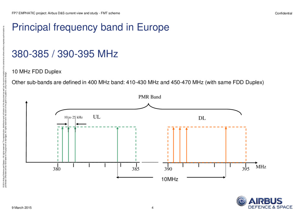
reserved. The reproduction, distribution and utilization of this document as well as the communication of its contents to others without express authorization is prohibited. Offenders will be held liable for the payment of damages. All rights reserved in the event of the grant of a patent, utility model or design. Principal frequency band in Europe 380-385 / 390-395 MHz 10 MHz FDD Duplex Other sub-bands are defined in 400 MHz band: 410-430 MHz and 450-470 MHz (with same FDD Duplex) 9 March 2015 FP7 EMPHATIC project: Airbus D&S current view and study - FMT scheme 4 380 385 390 395 PMR Band UL DL MHz 10 to 25 kHz 10MHz
reserved. The reproduction, distribution and utilization of this document as well as the communication of its contents to others without express authorization is prohibited. Offenders will be held liable for the payment of damages. All rights reserved in the event of the grant of a patent, utility model or design. PMR specific needs (services) Overall system architecture very similar to cell-based public radiocommunication systems (GSM/…) but: - Establishment time reduced to minimum - Group call / conference - Priority call / preemption - Emergency call - E2E encryption (cyphering in the handheld) - DMO (Direct Mode Operation) - Push to Talk - Very low datarate vocoder (down to 2.45kbits/s, ex. AMBE) - Very wide cell range (proprietary radio network) - … 9 March 2015 FP7 EMPHATIC project: Airbus D&S current view and study - FMT scheme 5
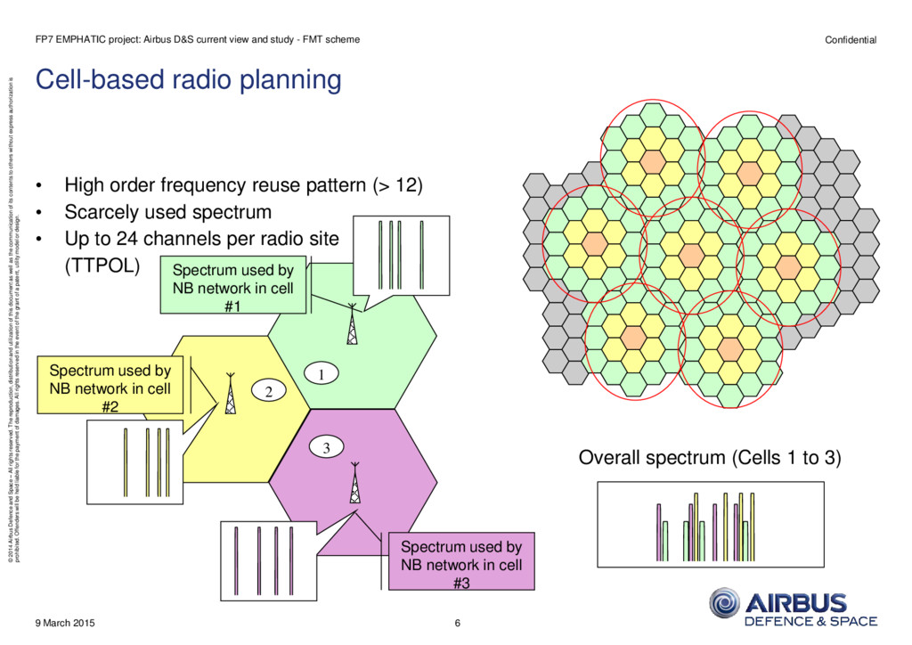
reserved. The reproduction, distribution and utilization of this document as well as the communication of its contents to others without express authorization is prohibited. Offenders will be held liable for the payment of damages. All rights reserved in the event of the grant of a patent, utility model or design. Cell-based radio planning • High order frequency reuse pattern (> 12) • Scarcely used spectrum • Up to 24 channels per radio site (TTPOL) 9 March 2015 FP7 EMPHATIC project: Airbus D&S current view and study - FMT scheme 6 1 2 3 Spectrum used by NB network in cell #2 Spectrum used by NB network in cell #1 Spectrum used by NB network in cell #3 Overall spectrum (Cells 1 to 3)
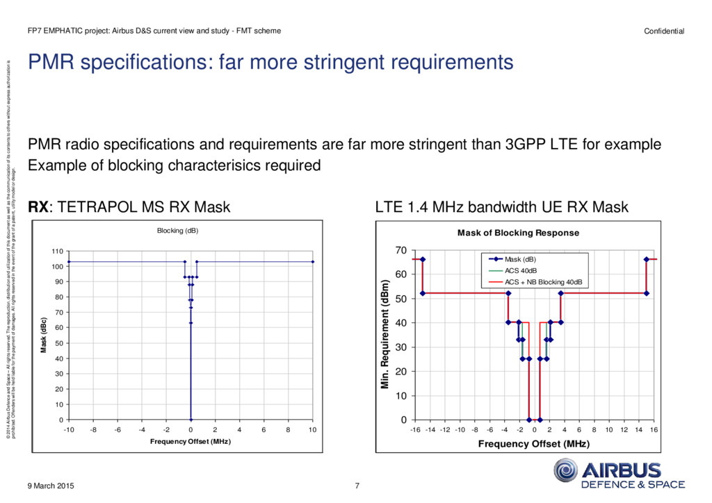
reserved. The reproduction, distribution and utilization of this document as well as the communication of its contents to others without express authorization is prohibited. Offenders will be held liable for the payment of damages. All rights reserved in the event of the grant of a patent, utility model or design. PMR specifications: far more stringent requirements PMR radio specifications and requirements are far more stringent than 3GPP LTE for example Example of blocking characterisics required RX: TETRAPOL MS RX Mask LTE 1.4 MHz bandwidth UE RX Mask 9 March 2015 FP7 EMPHATIC project: Airbus D&S current view and study - FMT scheme 7 Blocking (dB) 0 10 20 30 40 50 60 70 80 90 100 110 -10 -8 -6 -4 -2 0 2 4 6 8 10 Frequency Offset (MHz) Mask (dBc) Mask of Blocking Response 0 10 20 30 40 50 60 70 -16 -14 -12 -10 -8 -6 -4 -2 0 2 4 6 8 10 12 14 16 Frequency Offset (MHz) Min. Requirement (dBm) Mask (dB) ACS 40dB ACS + NB Blocking 40dB
reserved. The reproduction, distribution and utilization of this document as well as the communication of its contents to others without express authorization is prohibited. Offenders will be held liable for the payment of damages. All rights reserved in the event of the grant of a patent, utility model or design. Evolutions and context: higher datarates needed Hence the following important services that are of WB and BB nature cannot be supported by these networks: • video conferencing; • video streaming (CCTV on scene); • full Satellite Navigation (AVLS works well on narrowband but not as comprehensive); • passport and bio-metric checks (secure information) undertaken remotely as this requires data rates just above those available on narrowband; • improved on-line access to contacts data base that can be shared to know all those organisations / people that should be contacted depending on, for example, the incident; • full e-mail; • intranet browsing; • improved transfer of files (maps and pictures); • improved transfer of medical information; • ability to move the back office into the field; • Increased over the air key programming downloads of new software updates. Allows the staff to be kept operational which could be a significant cost and operational benefit; • Biometric monitoring; • … 9 March 2015 FP7 EMPHATIC project: Airbus D&S current view and study - FMT scheme 8
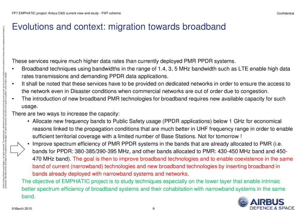
reserved. The reproduction, distribution and utilization of this document as well as the communication of its contents to others without express authorization is prohibited. Offenders will be held liable for the payment of damages. All rights reserved in the event of the grant of a patent, utility model or design. Evolutions and context: migration towards broadband These services require much higher data rates than currently deployed PMR PPDR systems. • Broadband techniques using bandwidths in the range of 1.4, 3, 5 MHz bandwidth such as LTE enable high data rates transmissions and demanding PPDR data applications. • It shall be noted that these services have to be provided on dedicated networks in order to ensure the access to the network even in Disaster conditions when commercial networks are out of order due to congestion. • The introduction of new broadband PMR technologies for broadband requires new available capacity for such usage. There are two ways to increase the capacity: • Allocate new frequency bands to Public Safety usage (PPDR applications) below 1 GHz for economical reasons linked to the propagation conditions that are much better in UHF frequency range in order to enable sufficient territorial coverage with a limited number of Base Stations. Not for tomorrow ! • Improve spectrum efficiency of PMR PPDR systems in the bands that are already allocated to PMR (i.e. bands for PPDR: 380-385/390-395 MHz, and other bands allocated to PMR: 430-450 MHz band and 450- 470 MHz band). The goal is then to improve broadband technologies and to enable coexistence in the same band of current (narrowband) technologies and new broadband technologies by inserting broadband in bands already deployed with narrowband systems and networks. The objective of EMPHATIC project is to study techniques especially on the lower layer that enable intrinsic better spectrum efficiency of broadband systems and their cohabitation with narrowband systems in the same band. 9 March 2015 FP7 EMPHATIC project: Airbus D&S current view and study - FMT scheme 9
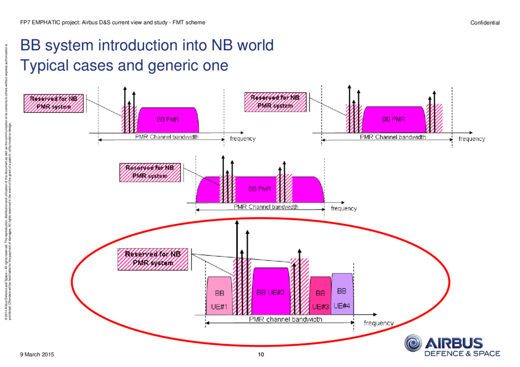
reserved. The reproduction, distribution and utilization of this document as well as the communication of its contents to others without express authorization is prohibited. Offenders will be held liable for the payment of damages. All rights reserved in the event of the grant of a patent, utility model or design. 9 March 2015 BB system introduction into NB world Typical cases and generic one 10 FP7 EMPHATIC project: Airbus D&S current view and study - FMT scheme 10
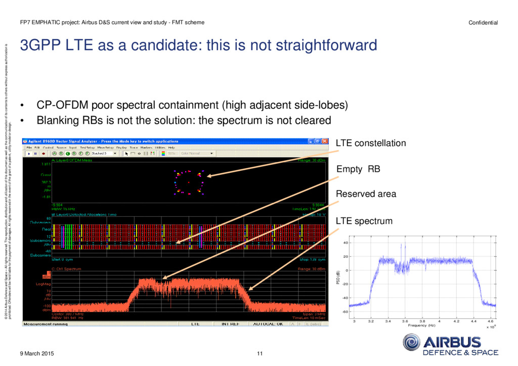
reserved. The reproduction, distribution and utilization of this document as well as the communication of its contents to others without express authorization is prohibited. Offenders will be held liable for the payment of damages. All rights reserved in the event of the grant of a patent, utility model or design. 3GPP LTE as a candidate: this is not straightforward • CP-OFDM poor spectral containment (high adjacent side-lobes) • Blanking RBs is not the solution: the spectrum is not cleared 9 March 2015 FP7 EMPHATIC project: Airbus D&S current view and study - FMT scheme 11 Empty RB LTE constellation LTE spectrum Reserved area 3 3.2 3.4 3.6 3.8 4 4.2 4.4 4.6 x 10⁶ -60 -40 -20 0 20 40 PSD (dB) Frequency (Hz)
reserved. The reproduction, distribution and utilization of this document as well as the communication of its contents to others without express authorization is prohibited. Offenders will be held liable for the payment of damages. All rights reserved in the event of the grant of a patent, utility model or design. Proposed solution: evolved 3GPP LTE Layer 1 using pulse shaping • Replace CP-OFDM by Filter Bank Multi-Carrier (FBMC) modulation: EMPHATIC purpose • Our own contribution: FMT usage • Frequency Multi Tone (FMT) : filter bank composed of non overlapping filters (or with slight overlapping) – frequency domain • Main idea: suppress temporal OFDM CP, and use an equivalent guard interval in the frequency domain • Iso radio resources, Fs unchanged, frame structure remains identical, … • Main advantage: spectrum shaping • Main drawback: temporal support of the pulse shaping function (delay) 9 March 2015 FP7 EMPHATIC project: Airbus D&S current view and study - FMT scheme 12
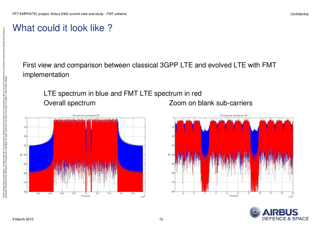
reserved. The reproduction, distribution and utilization of this document as well as the communication of its contents to others without express authorization is prohibited. Offenders will be held liable for the payment of damages. All rights reserved in the event of the grant of a patent, utility model or design. What could it look like ? First view and comparison between classical 3GPP LTE and evolved LTE with FMT implementation LTE spectrum in blue and FMT LTE spectrum in red Overall spectrum Zoom on blank sub-carriers 9 March 2015 FP7 EMPHATIC project: Airbus D&S current view and study - FMT scheme 13
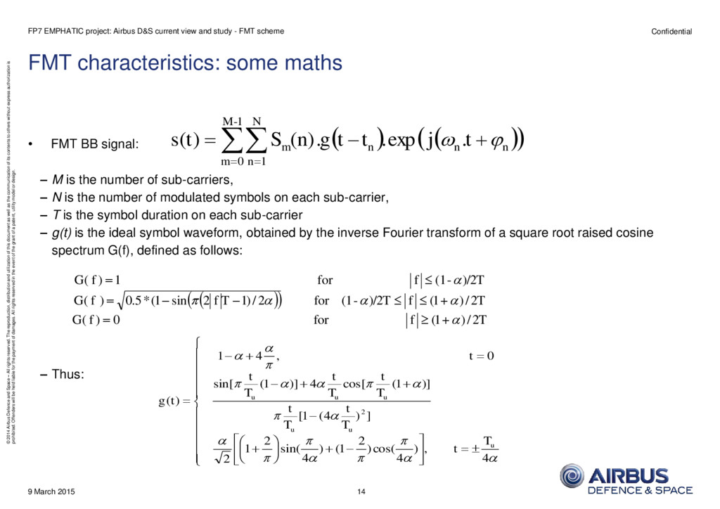
reserved. The reproduction, distribution and utilization of this document as well as the communication of its contents to others without express authorization is prohibited. Offenders will be held liable for the payment of damages. All rights reserved in the event of the grant of a patent, utility model or design. FMT characteristics: some maths • FMT BB signal: – M is the number of sub-carriers, – N is the number of modulated symbols on each sub-carrier, – T is the symbol duration on each sub-carrier – g(t) is the ideal symbol waveform, obtained by the inverse Fourier transform of a square root raised cosine spectrum G(f), defined as follows: – Thus: 9 March 2015 FP7 EMPHATIC project: Airbus D&S current view and study - FMT scheme n n n m t j t t g (n) S t s . exp . . ) ( 1 - M 0 m N 1 n T f f G T f T T f f G T f f G 2 / ) 1 ( for 0 ) ( 2 / ) 1 ( )/2 - (1 for 2 / ) 1 2 sin 1 ( * 5 . 0 ) ( )/2 - (1 for 1 ) ( 4 , ) 4 cos( ) 2 1 ( ) 4 sin( 2 1 2 ] ) 4 ( 1 [ )] 1 ( cos[ 4 )] 1 ( sin[ 0 , 4 1 ) ( 2 u u u u u u T t T t T t T t T t T t t t g 14
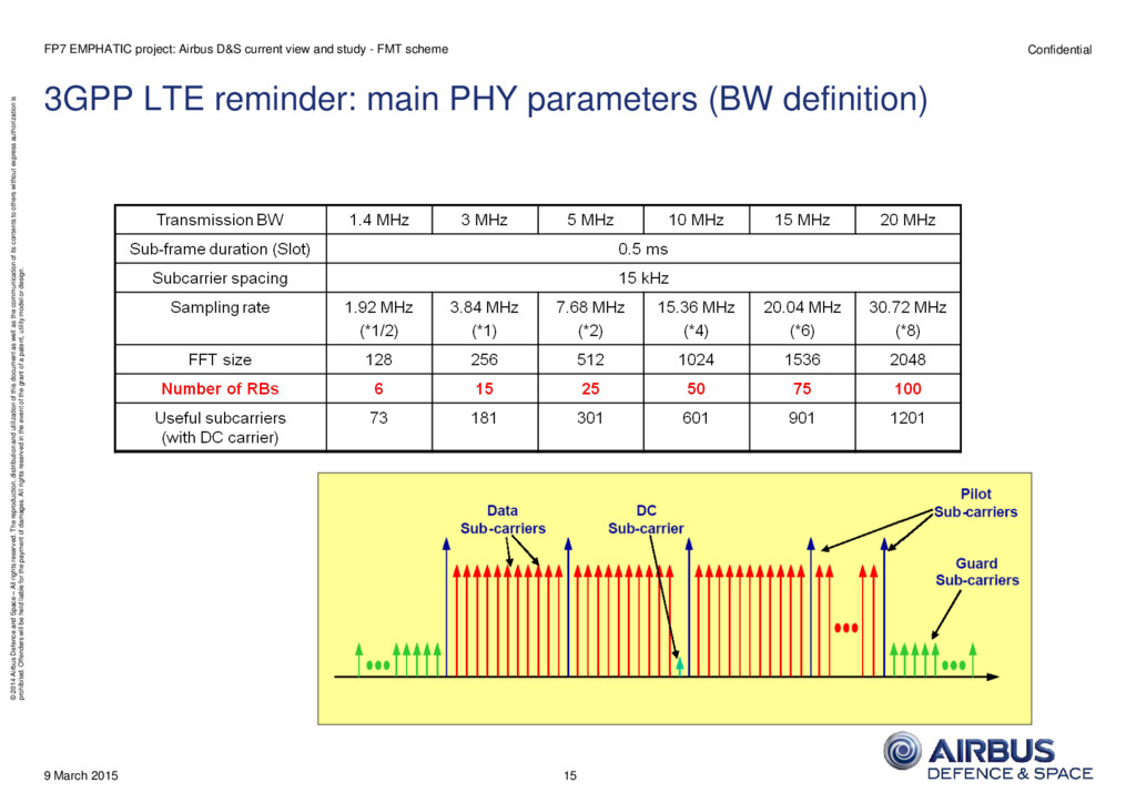
reserved. The reproduction, distribution and utilization of this document as well as the communication of its contents to others without express authorization is prohibited. Offenders will be held liable for the payment of damages. All rights reserved in the event of the grant of a patent, utility model or design. 3GPP LTE reminder: main PHY parameters (BW definition) 9 March 2015 FP7 EMPHATIC project: Airbus D&S current view and study - FMT scheme 15
reserved. The reproduction, distribution and utilization of this document as well as the communication of its contents to others without express authorization is prohibited. Offenders will be held liable for the payment of damages. All rights reserved in the event of the grant of a patent, utility model or design. 3GPP LTE DL physical channels reminder 9 March 2015 FP7 EMPHATIC project: Airbus D&S current view and study - FMT scheme 16
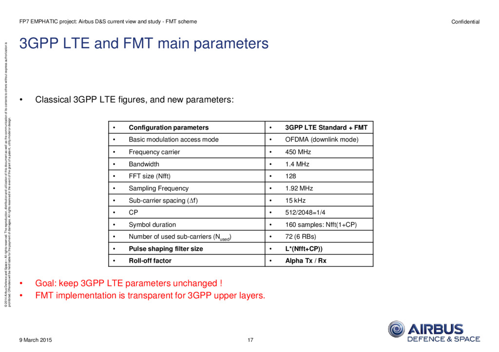
reserved. The reproduction, distribution and utilization of this document as well as the communication of its contents to others without express authorization is prohibited. Offenders will be held liable for the payment of damages. All rights reserved in the event of the grant of a patent, utility model or design. 3GPP LTE and FMT main parameters • Classical 3GPP LTE figures, and new parameters: • Goal: keep 3GPP LTE parameters unchanged ! • FMT implementation is transparent for 3GPP upper layers. 9 March 2015 FP7 EMPHATIC project: Airbus D&S current view and study - FMT scheme • Configuration parameters • 3GPP LTE Standard + FMT • Basic modulation access mode • OFDMA (downlink mode) • Frequency carrier • 450 MHz • Bandwidth • 1.4 MHz • FFT size (Nfft) • 128 • Sampling Frequency • 1.92 MHz • Sub-carrier spacing (∆f) • 15 kHz • CP • 512/2048=1/4 • Symbol duration • 160 samples: Nfft(1+CP) • Number of used sub-carriers (N used ) • 72 (6 RBs) • Pulse shaping filter size • L*(Nfft+CP)) • Roll-off factor • Alpha Tx / Rx 17
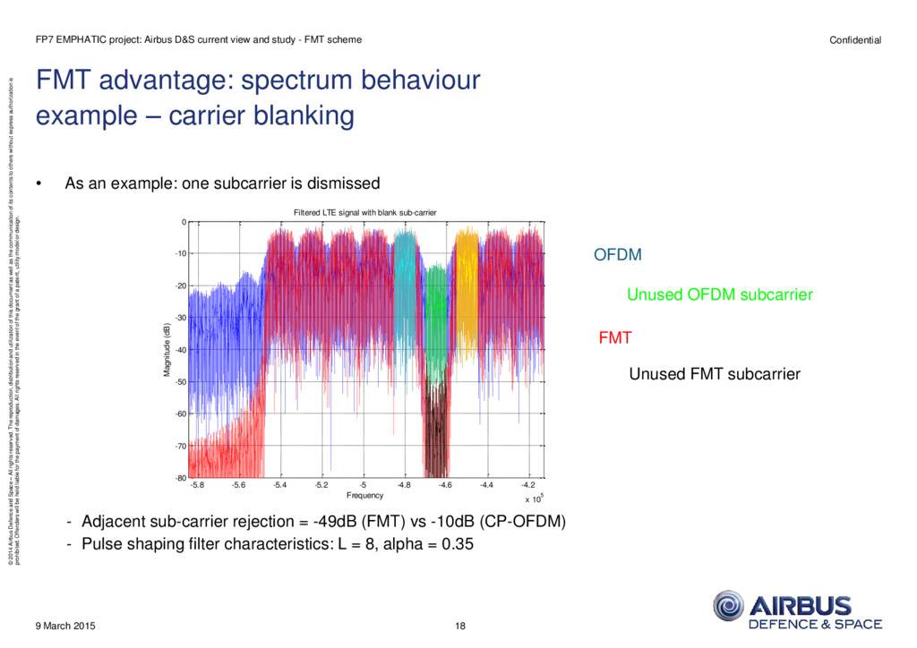
reserved. The reproduction, distribution and utilization of this document as well as the communication of its contents to others without express authorization is prohibited. Offenders will be held liable for the payment of damages. All rights reserved in the event of the grant of a patent, utility model or design. FMT advantage: spectrum behaviour example – carrier blanking • As an example: one subcarrier is dismissed - Adjacent sub-carrier rejection = -49dB (FMT) vs -10dB (CP-OFDM) - Pulse shaping filter characteristics: L = 8, alpha = 0.35 9 March 2015 FP7 EMPHATIC project: Airbus D&S current view and study - FMT scheme -5.8 -5.6 -5.4 -5.2 -5 -4.8 -4.6 -4.4 -4.2 x 10⁵ -80 -70 -60 -50 -40 -30 -20 -10 0 Frequency Magnitude (dB) Filtered LTE signal with blank sub-carrier OFDM FMT Unused OFDM subcarrier Unused FMT subcarrier 18
reserved. The reproduction, distribution and utilization of this document as well as the communication of its contents to others without express authorization is prohibited. Offenders will be held liable for the payment of damages. All rights reserved in the event of the grant of a patent, utility model or design. FMT drawback: ICI / limited pulse shaping temporal support example – EVM at receiver side (no propagation channel) • Depending on temporal pulse shaping length and truncation, EVM could be not negligible (ideal case – no propagation channel): 9 March 2015 FP7 EMPHATIC project: Airbus D&S current view and study - FMT scheme -1.5 -1 -0.5 0 0.5 1 1.5 -1.5 -1 -0.5 0 0.5 1 1.5 64 QAM symbols, L=6, Alpha= 0.33, EVM=0.041 -1.5 -1 -0.5 0 0.5 1 1.5 -1.5 -1 -0.5 0 0.5 1 1.5 64 QAM symbols, L=7, Alpha=0.33, EVM=0.02 -1.5 -1 -0.5 0 0.5 1 1.5 -1.5 -1 -0.5 0 0.5 1 1.5 64 QAM symbols, L=18, Alpha=0.23, EVM=0.003 19
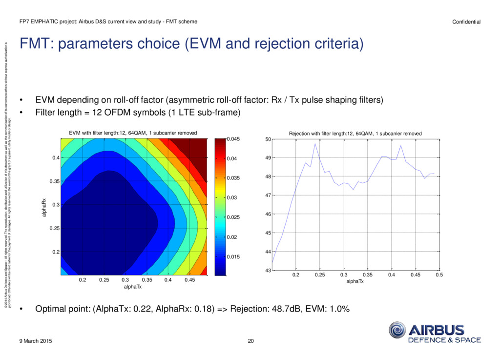
reserved. The reproduction, distribution and utilization of this document as well as the communication of its contents to others without express authorization is prohibited. Offenders will be held liable for the payment of damages. All rights reserved in the event of the grant of a patent, utility model or design. FMT: parameters choice (EVM and rejection criteria) • EVM depending on roll-off factor (asymmetric roll-off factor: Rx / Tx pulse shaping filters) • Filter length = 12 OFDM symbols (1 LTE sub-frame) • Optimal point: (AlphaTx: 0.22, AlphaRx: 0.18) => Rejection: 48.7dB, EVM: 1.0% 9 March 2015 FP7 EMPHATIC project: Airbus D&S current view and study - FMT scheme alphaTx alphaRx EVM with filter length:12, 64QAM, 1 subcarrier removed 0.2 0.25 0.3 0.35 0.4 0.45 0.2 0.25 0.3 0.35 0.4 0.015 0.02 0.025 0.03 0.035 0.04 0.045 0.2 0.25 0.3 0.35 0.4 0.45 0.5 43 44 45 46 47 48 49 50 Rejection with filter length:12, 64QAM, 1 subcarrier removed alphaTx 20
reserved. The reproduction, distribution and utilization of this document as well as the communication of its contents to others without express authorization is prohibited. Offenders will be held liable for the payment of damages. All rights reserved in the event of the grant of a patent, utility model or design. FMT modulator - basics 9 March 2015 FP7 EMPHATIC project: Airbus D&S current view and study - FMT scheme Pulse Shape Filter h (t) e j 0 t tx Subchannel 0 Subchannel Symbol Generator Pulse Shape Filter h (t) e j t 1 tx Subchannel 1 Subchannel Symbol Generator Pulse Shape Filter h (t) e j t N-1 tx Subchannel N-1 Subchannel Symbol Generator + Zero IF Modulation Data Input 0 Data Input 1 Data Input N-1 k bits k bits k bits 21
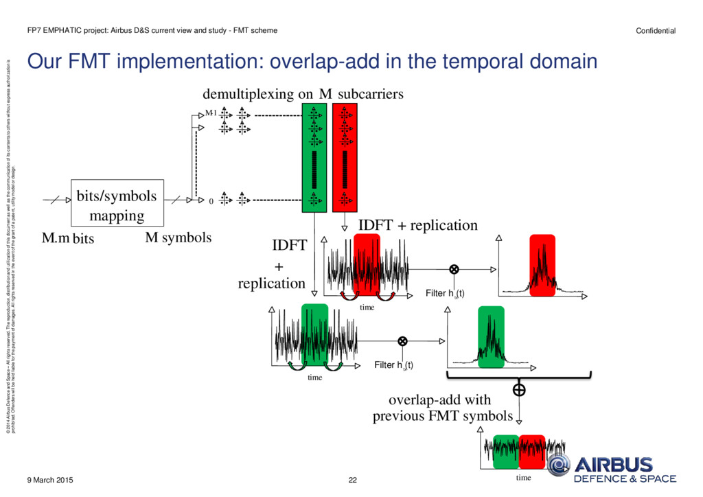
reserved. The reproduction, distribution and utilization of this document as well as the communication of its contents to others without express authorization is prohibited. Offenders will be held liable for the payment of damages. All rights reserved in the event of the grant of a patent, utility model or design. Our FMT implementation: overlap-add in the temporal domain 9 March 2015 FP7 EMPHATIC project: Airbus D&S current view and study - FMT scheme IDFT + replication overlap-add with previous FMT symbols M.m bits bits/ symbols mapping M symbols demultiplexing on M subcarriers 0 M -1 .. .. .. .. .. .. .. .. .. .. .. .. .. .. .. .. .. .. .. .. .. .. .. .. .. .. .. .. IDFT + replication time time Filter h (t) tx Filter h (t) tx time 22
reserved. The reproduction, distribution and utilization of this document as well as the communication of its contents to others without express authorization is prohibited. Offenders will be held liable for the payment of damages. All rights reserved in the event of the grant of a patent, utility model or design. MATLAB LTE / FMT PHY simulation: overall synoptic (DL case) • Complete PHY layer simulation available: Synchronization in time and frequency is perfect ! 9 March 2015 FP7 EMPHATIC project: Airbus D&S current view and study - FMT scheme Data bits CHANNEL CODING CRC encoder Rando- mizer FEC encoder Inter- leaver Rate mat- ching SYMBOL QAM mapper MIMO MIMO encoder BURST MAPPING PHY-channel mapping PN seq. generator Pilots insertion Frame structure OFDM IFFT CP insert. PROPAGATION CHANNEL Multiple paths Delays Uncorrelated fadings Multiple paths summation AWGN FFT CP remove OFDM INIT MIMO decoder & Channel estimation Channel compensate PHY-channel demapping Pilots removal QAM Demod. Received Data bits CRC decoder Derand- omizer FEC decoder Deinter- leaver Rate demat- ching BER/FER calculation + EVM FMT FMT 23
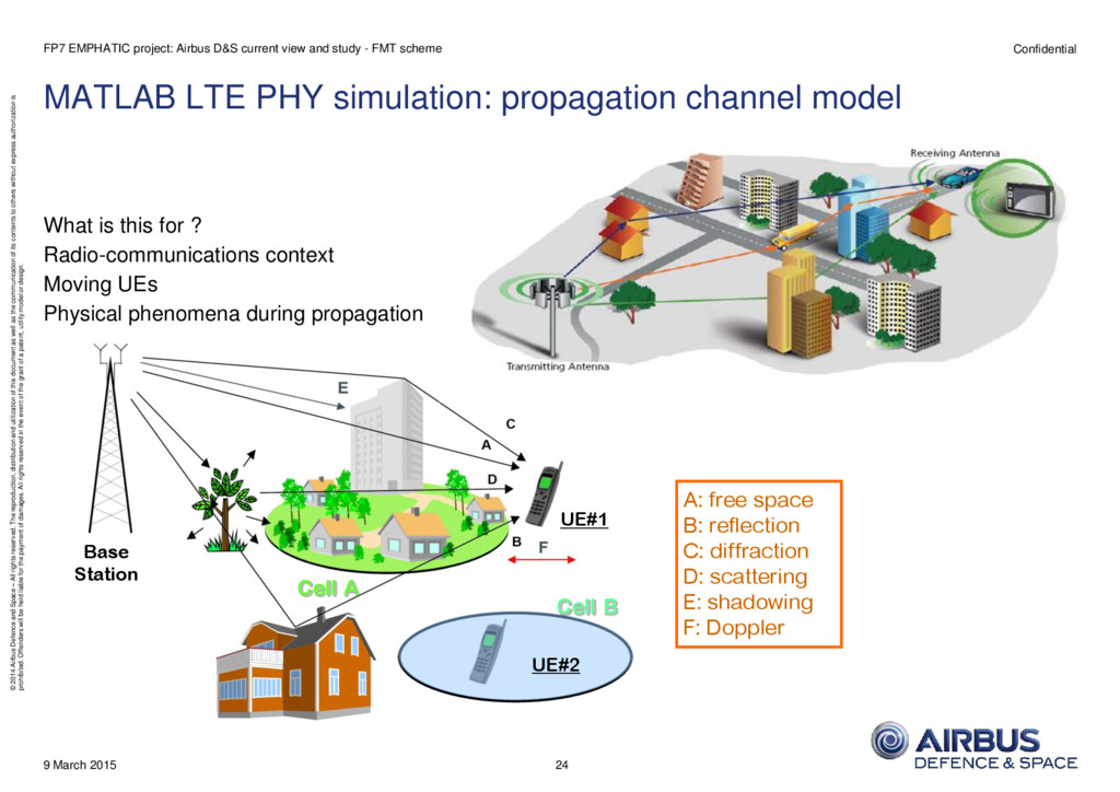
reserved. The reproduction, distribution and utilization of this document as well as the communication of its contents to others without express authorization is prohibited. Offenders will be held liable for the payment of damages. All rights reserved in the event of the grant of a patent, utility model or design. MATLAB LTE PHY simulation: propagation channel model What is this for ? Radio-communications context Moving UEs Physical phenomena during propagation 9 March 2015 FP7 EMPHATIC project: Airbus D&S current view and study - FMT scheme 24 UE#1 Base Station UE#2 Cell B Cell A A: free space B: reflection C: diffraction D: scattering E: shadowing F: Doppler
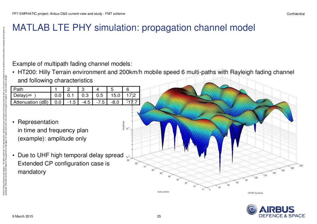
reserved. The reproduction, distribution and utilization of this document as well as the communication of its contents to others without express authorization is prohibited. Offenders will be held liable for the payment of damages. All rights reserved in the event of the grant of a patent, utility model or design. MATLAB LTE PHY simulation: propagation channel model Example of multipath fading channel models: • HT200: Hilly Terrain environment and 200km/h mobile speed 6 multi-paths with Rayleigh fading channel and following characteristics • Representation in time and frequency plan (example): amplitude only • Due to UHF high temporal delay spread Extended CP configuration case is mandatory 9 March 2015 FP7 EMPHATIC project: Airbus D&S current view and study - FMT scheme 25 Path 1 2 3 4 5 6 Delay( s ) 0.0 0.1 0.3 0.5 15.0 17.2 Attenuation (dB) 0.0 -1.5 -4.5 -7.5 -8.0 -17.7
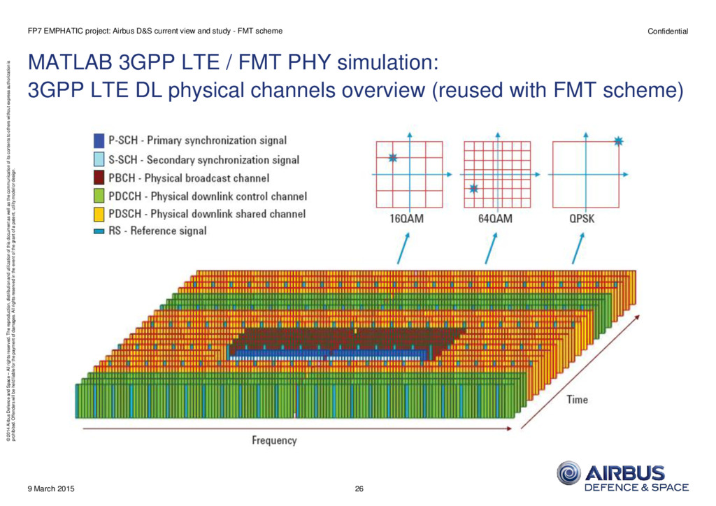
reserved. The reproduction, distribution and utilization of this document as well as the communication of its contents to others without express authorization is prohibited. Offenders will be held liable for the payment of damages. All rights reserved in the event of the grant of a patent, utility model or design. MATLAB 3GPP LTE / FMT PHY simulation: 3GPP LTE DL physical channels overview (reused with FMT scheme) 9 March 2015 FP7 EMPHATIC project: Airbus D&S current view and study - FMT scheme 26
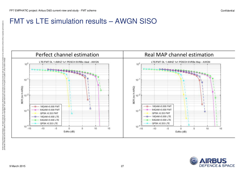
reserved. The reproduction, distribution and utilization of this document as well as the communication of its contents to others without express authorization is prohibited. Offenders will be held liable for the payment of damages. All rights reserved in the event of the grant of a patent, utility model or design. FMT vs LTE simulation results – AWGN SISO 9 March 2015 FP7 EMPHATIC project: Airbus D&S current view and study - FMT scheme Perfect channel estimation Real MAP channel estimation 27
reserved. The reproduction, distribution and utilization of this document as well as the communication of its contents to others without express authorization is prohibited. Offenders will be held liable for the payment of damages. All rights reserved in the event of the grant of a patent, utility model or design. FMT vs LTE simulation results – dynamic EVA 50 SISO 9 March 2015 FP7 EMPHATIC project: Airbus D&S current view and study - FMT scheme 28 Perfect channel estimation Real MAP channel estimation
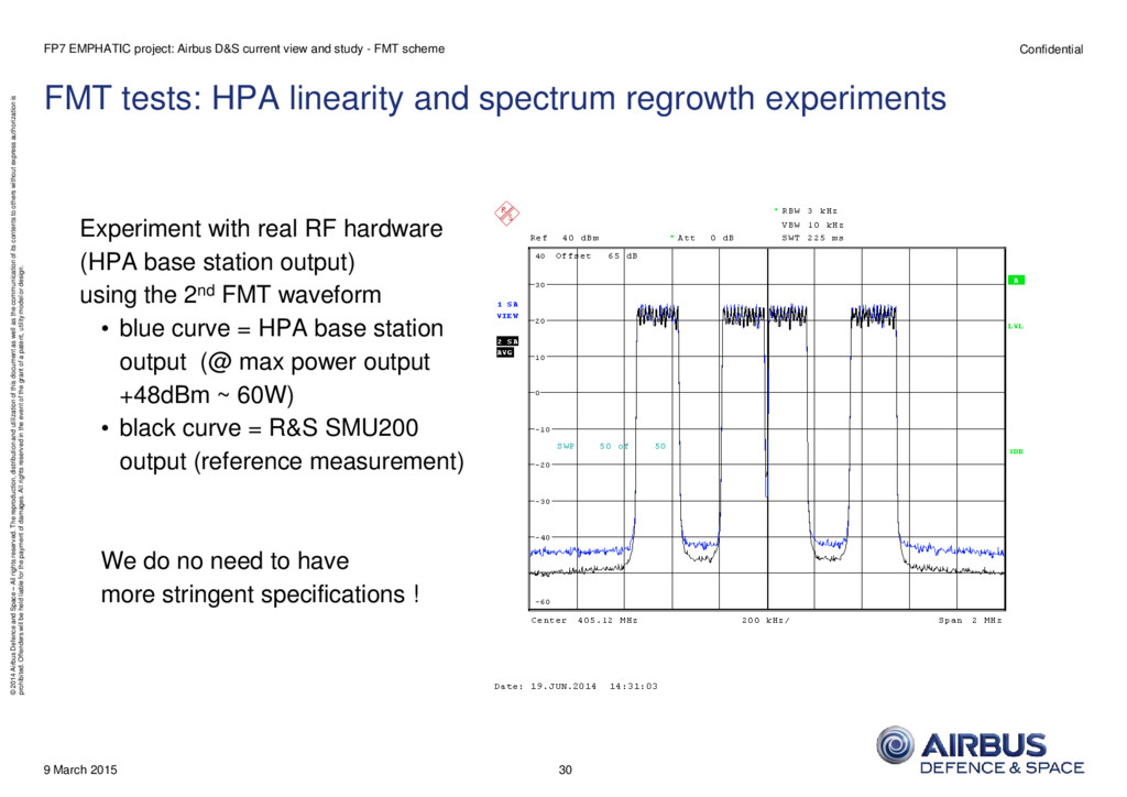
reserved. The reproduction, distribution and utilization of this document as well as the communication of its contents to others without express authorization is prohibited. Offenders will be held liable for the payment of damages. All rights reserved in the event of the grant of a patent, utility model or design. FMT tests: HPA linearity and spectrum regrowth experiments Several waveforms generated with the following characteristics and feeding Base Station HPA: • Fs = 7.68Msamples/s • No Crest Factor reduction is applied (as a consequence, PAPR is roughly 12dB) • Modulation = 64QAM • BW = 1.4MHz (6 RBs) • Two RBs are blanked CP-OFDM 3GPP LTE waveform 1st FMT waveform: L = 6, roll-off = 0.25 (ACP rejection ~ 40dB) 2nd FMT waveform: L = 12, roll-off = 0.25 (ACP rejection ~ 60dB) 9 March 2015 FP7 EMPHATIC project: Airbus D&S current view and study - FMT scheme 29
reserved. The reproduction, distribution and utilization of this document as well as the communication of its contents to others without express authorization is prohibited. Offenders will be held liable for the payment of damages. All rights reserved in the event of the grant of a patent, utility model or design. FMT tests: HPA linearity and spectrum regrowth experiments Experiment with real RF hardware (HPA base station output) using the 2nd FMT waveform • blue curve = HPA base station output (@ max power output +48dBm ~ 60W) • black curve = R&S SMU200 output (reference measurement) We do no need to have more stringent specifications ! 9 March 2015 FP7 EMPHATIC project: Airbus D&S current view and study - FMT scheme 30
reserved. The reproduction, distribution and utilization of this document as well as the communication of its contents to others without express authorization is prohibited. Offenders will be held liable for the payment of damages. All rights reserved in the event of the grant of a patent, utility model or design. 9 March 2015 Thank you for your attention! Questions ? 31 FP7 EMPHATIC project: Airbus D&S current view and study - FMT scheme 31