Upgrade to Pro — share decks privately, control downloads, hide ads and more …

IEEE BMSB 2025 @ Dublin, Ireland

IEEE BMSB 2025 @ Dublin, Ireland

https://www.eeng.dcu.ie/~bmsb2025/program.html

Session 1A
1A: Next Generation TV (6 papers)

Irish Standard Time
June 11, 10:30 - 12:30

Location
Polaris Building Room: FTG13

SESSION CHAIRS
Moyukh Laha, Cristiano Akamine

Avatar for Sungho Jeon

Sungho Jeon

June 11, 2025
Tweet

More Decks by Sungho Jeon

Other Decks in Technology

Transcript

  1. ATSC 3.0 STLTP Distribution over Multicast-Unsupported VPN Session 1A: Next

    Generation TV Polaris Building Room: FTG13 June 11, 10:30 - 12:30 Sungho Jeon, Seongman Min, Moonsun Kang, Jae Hun You (KBS), Sunhyung Kwon, Sung-Ik Park (ETRI) The 20th IEEE International Symposium on Broadband Multimedia Systems and Broadcasting will be held in the Faculty of Engineering and Computing, Dublin City University, Ireland, from 11-13 June 2025.
  2. KBS ATSC 3.0 SFN Broadcast Network Status 2 2 3

    3 2 3 2 3 1 1 1 1 1 1 2 2 3 2 2 1 2 2 2 2 3 2 2 3 3 3 3 2 3 2 2 2 2 2 3 3 3 3 3 3 3 3 3 4 3 2 2 1 1 2 1 2 4 5 2 3 2 3 3 ATSC 3.0 Transmitter ATSC 3.0 Headend A coverage prediction map of ATSC 3.0 service simulated using a planning tool. In accordance with government policy, KBS is expanding its SFN broadcast network annually, and as of March 2025, the network covers 80% of the population. KBS1 is operated as a Regional SFN, KBS2 is operated as a Nationwide SFN 1 2 2 1
  3. KBS Nationwide ATSC 3.0 SFN Monitoring System Real-time Measurement Monitoring

    Unit Standardization of ATSC 3.0 Monitoring Integrated Monitoring Dashboard Remote Monitoring Device with GPS Synchronization for Transmitter Stations Remote Monitoring Unit with PTP Synchronization for Broadcast Headend Network-Topology based Dashboard Real-time Measurement Performance Indicators Leading Domestic Standards Development Ahead of North America Monitoring Guideline for Terrestrial UHD Systems Guideline for TxIDand BSID Assignment of Terrestrial UHD Systems As of 11:00 AM, March 5, 2025, 68,000 hours have elapsed ✓ KBS has maintained continuous 24/7 operation since the world's first ATSC 3.0 terrestrial broadcast launch in May 2017. ✓ Leveraging years of stable nationwide SFN operation, KBS leads the development and standardization of advanced monitoring systems. [1] Sungho Jeon, et. al., “Simple Anomaly Detection Technique from Long-term Time-series Data by ATSC 3.0 Single Frequency Broadcast Network Monitoring System,” in The 18th IEEE International Symposium on Broadband Multimedia Systems and Broadcasting (BMSB 2023), Beijing, China, June 2023. [2] Sungho Jeon, et. al., “Nationwide Integrated 24/7 Monitoring System for ATSC 3.0 Single Frequency Broadcast Network,” in The 17th IEEE International Symposium on Broadband Multimedia Systems and Broadcasting (BMSB 2022), Bilbao, Spain, June 2022.
  4. Intermittent fading causing signal loss in long-distance MW links Heukseung

    Wonhyobong Wonhyobong Heukseung 55km Daejeon (b) between Heukseongsan Relay Transmitter and Wonhyobong Relay Transmitter Jeonju Moak Nogodan Moak Nogodan 63km Jeonju Distribution network structure and location (a) between Jeonju Station and Nogodan Relay Transmitter Microwave fading causing signal attenuation at Nogodan and Wonhyobong receiver sides
  5. Severe fading may cause signal loss or interruption. Frequent short-term

    fading can trigger ATSC 3.0 distribution switch port down. Packet Drop @Nogodan Network Input Loss @Nogodan (b) ATSC 3.0 SFN Monitoring Log (a) EUROTEK Microwave Monitoring Log M/W Rx Level [dBm] @Nogodan Intermittent fading causing signal loss in long-distance MW links * CISCO Switch Network Management Alarm Log * CISCO Switch System Log
  6. Efforts to Stabilize Moaksan to Nogodan Microwave Link: Improving Receiver

    Sensitivity (a) Power Adjustment (Nov. 2023) ✓ Increased M/W output from 1W to 1.6W and monitored results ✓ Same fading symptoms occurred → Reverted to 1W (b) Modulation Order Change (Dec. 2023) ✓ Changed modulation from 128QAM to 64QAM and monitored results ✓ Same fading symptoms occurred → Reverted to 128QAM Only solution so far: Dedicated ISP leased line installation Public Internet Enterprise VPN Dedicated ISP Leased Network High stability Less stable Cost-effective High cost
  7. Why Only a Leased Line (Until Now)? Public Internet Enterprise

    VPN Dedicated ISP Leased Network High stability Less stable Cost-effective High cost Option Public Internet Enterprise VPN Dedicated Line Pros • Very low monthly cost • Reasonable monthly cost • Quality/stability guaranteed within pre-agreed bandwidth • 100% guaranteed transmission quality and stability • Full Multicast support Cons • No guarantee of transmission quality or stability • No Multicast support. Unicast Only • No Multicast support • Very high monthly cost Summary Not suitable for broadcast signal distribution Could be the most viable option if Multicast is supported Only current solution for STLTP over broadband STLTP Signal Distribution: Network Options Comparison
  8. Why Only a Leased Line (Until Now)? Public Internet Enterprise

    VPN Dedicated ISP Leased Network High stability Less stable Cost-effective High cost 60 Mbps STLTP Transmission (KBS1: 30 Mbps + KBS2: 30 Mbps) Category Public Internet Enterprise VPN Dedicated Leased Line Monthly Cost $20 $200 $2,000 Feasibility Not usable Viable if multicast support is added Fully usable Remarks No stability No multicast support Stable within contracted bandwidth No multicast support High stability Full multicast support * Since not all routers along the transmission path in the public Internet support multicast, a single non-supporting router will prevent multicast transmission. As a result, unicast must be used instead.
  9. A/324 Figure D.1: RTP/UDP/IP Unicast for outer tunnel packets using

    CTP (Common Tunneling Protocol) redundancy Defined in standard: ATSC 3.0 A/324 Annex D allows STLTP delivery over public networks using Unicast. Key Mechanism: • STLTP packets are transmitted via multiple ISPs using Unicast • At the transmitter, all identical STLTP streams are received • Packet aggregation is used to recover dropped packets and compensate for jitter → Achieves probabilistic reliability despite unstable public networks Unicast-based STLTP Delivery over Public Internet Pros & Cons of Public Internet + Unicast STLTP Delivery Aspect Details Advantage • Low cost due to use of public Internet Disadvantages • BGW & Exciter must support Unicast TX/RX (KBS BGW: not supported) • Public Internet cannot guarantee Multicast compatibility across all routers • Requires bandwidth scaling with number of ISPs × TX sites * Bandwidth Example: KBS1 STLTP = 30 Mbps Using 3 ISPs for 1 TX site → 90 Mbps required for 2 TX sites → 180 Mbps required
  10. VPN through ISP SRT Caller SRT Listener 20.0Mbps 239.255.14.156:5000 20.0Mbps

    VPN through ISP L3 Switch @CISCO NEXUS L3 Switch @CISCO NEXUS GRE Tunneling 10.0Mbps 239.255.14.156:5002 239.255.14.156:5004 20.0Mbps 239.255.14.156:5000 20.0Mbps 10.0Mbps 239.255.14.156:5002 239.255.14.156:5004 20.0Mbps 10.0Mbps 20.0Mbps 10.0Mbps 20.0Mbps Multicast Unicast (L,D) =(6,6) (L,D) =(6,6) SRT ARQ To Exciter To Exciter SRT-IP:5000 Method 2: Using GRE (Generic Routing Encapsulation) Tunneling Method 1: Using SRT (Secure Reliable Transport) Proposed Methods for Multicast Distribution over Multicast-Unsupported VPNs
  11. Comparison of Technical Specifications: Method 1(SRT) and Method 2 (GRE

    Tunneling) Method Feature Method 1 (SRT) Method 2 (GRE Tunneling) Requirements Requires dedicated SRT Caller and Listener devices Requires L3 switches with GRE tunneling capability at both ends Additional Delay Minimum 120 ms (due to ARQ buffer latency) None Transmission Rate Same as ATSC 3.0 BGW output, excluding FEC Same as ATSC 3.0 BGW output Error Correction Performance Fixed error correction performance based on ARQ Variable depending on STL-FEC settings Exciter Input Connection Direct connection to exciter due to multicast RPF issue Indirect connection via L3 Switch Important Notes Rather than increasing the transmission rate by applying SRT FEC, it is generally recommended not to apply FEC in most cases. Since a GRE header is added, the BGW output packet size must be set to within 1,436 bytes. Each multicast stream requires a separate VPN subnet or L3 switch.
  12. R2 Fa0/0 From ATSC 3.0 BGW Fa0/1 Fa0/1 To Exciter

    Fa0/0 ISP VPN # cd /root/loopback-main # ./loopback –input udp://239.255.9.136: 5000?adapter=100.135.253.162 –output udp ://127.0.0.1:8888?adapter=127.0.0.1 & # srt-live-transmit udp://:8888 srt://20 5.24.1.49:8082 –v & # srt-live-transmit -v -r 5000 -s 5000 " srt://:8082?mode=listener“ "udp://239.25 5.9.136:5000?adapter=100.135.253.169“ & Microwave SRT Caller SRT Listener To Exciter @SRT Caller [Daejeon] @SRT Listener [Wonhyobong] Method 1 (SRT) R1 Configuration and Detailed Settings of SRT Application on Daejeon Station - Wonhyobong Transmitter ✓ On the SRT caller device, the STLTP multicast stream received from the ATSC 3.0 BGW is looped back to the localhost (127.0.0.1) to maintain the IGMP connection, ensuring continuous reception of the signal. This looped multicast stream is then transmitted via the SRT protocol using the srt-live-transmit command, which sends it to the IP address of the SRT listener. The listener device is configured explicitly with ?mode=listener and forwards the received SRT data to the designated STLTP multicast IP via UDP.
  13. Method 1 (SRT) Wonhyobong ATSC 3.0 transmitter input signal configuration

    Microwave ATSC 3.0 BGW Daejeon_Main Daejeon (Studio) Daejeon_Backup Heukseong TX A, B Wonhyobong Microwave Microwave Wonhyo_Main Wonhyo_Backup Microwave On-Air On-Air VPN TX A TX B SRT Caller SRT Listener Input#1 Input#2 Input#1 Input#2 connected directly to the transmitter input, bypassing the switch
  14. Daejeon Broadcasting Center (Main Equipment Room) Wonhyobong ATSC 3.0 transmitter

    input signal configuration Method 1 (SRT) Approximately 20 Mbps out of the original 27 Mbps output from the ATSC 3.0 BGW (excluding the FEC portion) is observed on the ISP’s traffic monitoring system. VPN
  15. Daejeon Broadcasting Center (Main Equipment Room) VPN Measured Latency: +125

    ms Wonhyobong ATSC 3.0 transmitter input signal configuration Method 1 (SRT) Wonhyobong Relay Station
  16. Method 1 (SRT) Wonhyobong KBS 2TV transmitter TX-B after applying

    the SRT method (b) SFN delay measurement (a) Input#2 status ✓ After implementing the SRT method, the Input#2 signal status of the ATSC 3.0 TX-B transmitter indicates normal operation. The total delay remains within 600 ms, satisfying KBS ATSC 3.0 SFN (Single Frequency Network) requirements and enabling stable operation. ✓ However, as shown in Table II, the delay difference between Input#1 and Input#2 of the transmitter exceeds 100 ms, preventing the use of Seamless Switching feature. Consequently, the transmitter TX-B is configured with Seamless Switching functionality turned off for operation.
  17. GRE Tunnel Function of ATSC 3.0 STLTP Transmission L3 Switch

    UHD IP Signal Transmission Architecture – Jeonju CISCO L3 Switch ✓ Multicast transmission : Enable PIM Sparse-Mode functionality ✓ All nationwide ATSC 3.0 STLTP transmission switches are Cisco devices, with GRE tunnel support varying by installation year. • GRE tunneling is supported between Jeonju Broadcasting Center and Nogodan Station. Method 2 (GRE Tunneling) ✓ ATSC 3.0 STLTP signals are transmitted and distributed to their destinations via Layer 3 transmission switches located at the broadcast center and relay stations. Broadcast Center Relay Station
  18. Configuring GRE Tunnel (1/2) Configuring a GRE tunnel involves creating

    a tunnel interface, which is a logical interface. Then you must configure the tunnel endpoints for the tunnel interface. To configure the tunnel source and destination, issue the tunnel source {ip-address | interface-type} and tunnel destination {host-name | ip-address} com mands under the interface configuration mode for the tunnel. The below example explain about how to create simple GRE tunnels between endpoints and the necessary steps to create and verify the GRE tunnel between the two networks. R1's and R2's Internal subnets (192.168.1.0/24 and 192.168.2.0/24) are communicating with each other using GRE tunnel over internet. Both Tunnel interfaces are part of the 172.16.1.0/24 network. https://community.cisco.com/t5/networking-knowledge-base/how-to-configure-a-gre-tunnel/ta-p/3131970 R1 R2 Fa0/0 Internet Network 192.168.1.0/24 Tunnel Interface 1 172.16.1.1/24 Fa0/1 Fa0/1 Tunnel Interface 1 172.16.1.2/24 Internet Network 192.168.2.0/24 Fa0/0 ISP RFC 2784
  19. Configuring GRE Tunnel (2/2) Since GRE is an encapsulating protocol,

    we adjust the maximum transfer unit (MTU) to 1400 bytes and maximum se gment size (MSS) to 1360 bytes. Because most transport MTUs are 1500 bytes and we have an added overhead bec ause of GRE, we must reduce the MTU to account for the extra overhead. A setting of 1400 is a common practice an d will ensure unnecessary packet fragmentation is kept to a minimum. https://community.cisco.com/t5/networking-knowledge-base/how-to-configure-a-gre-tunnel/ta-p/3131970 1 R1(config)# interface Tunnel1 2 R1(config-if)# ip address 172.16.1.1 255.255.255.0 3 R1(config-if)# ip mtu 1400 4 R1(config-if)# ip tcp adjust-mss 1360 5 R1(config-if)# tunnel source 1.1.1.1 6 R1(config-if)# tunnel destination 2.2.2.2 1 R2(config)# interface Tunnel1 2 R2(config-if)# ip address 172.16.1.2 255.255.255.0 3 R2(config-if)# ip mtu 1400 4 R2(config-if)# ip tcp adjust-mss 1360 5 R2(config-if)# tunnel source 2.2.2.2 6 R2(config-if)# tunnel destination 1.1.1.1 R1 R2 Fa0/0 Internet Network 192.168.1.0/24 Tunnel Interface 1 172.16.1.1/24 Fa0/1 Fa0/1 Tunnel Interface 1 172.16.1.2/24 Internet Network 192.168.2.0/24 Fa0/0 ISP 1,436 bytes [payload] + 20 bytes [TCP header] + 20 bytes [IP header] + 24 bytes [ 4 GRE header + 20 IP header] = 1,500 bytes 1.1.1.1/30 2.2.2.2/30 RFC 2784 1 R1(config)# ip route 192.168.2.0 255.255.255.0 172.16.1.2 1 R2(config)# ip route 192.168.1.0 255.255.255.0 172.16.1.1
  20. R2 Fa0/0 From ATSC 3.0 BGW Fa0/1 Fa0/1 To Exciter

    Fa0/0 ISP VPN Microwave SRT Listener @R1 [Jeonju] @R2 [Nogodan] Interface tunnel 9 ip address 100.135.100.1 255.255.255.252 ip pim sparse-mode tunnel source 205.18.5.49 tunnel destination 205.18.6.49 Interface Gi1/0/19 no switchport ip address 205.18.5.49 255.255.255.0 Ip route 205.18.6.0 255.255.255.0 205.18.5.1 Interface tunnel 9 ip address 100.135.100.2 255.255.255.252 ip pim sparse-mode tunnel source 205.18.6.49 tunnel destination 205.18.5.49 Interface Gi1/0/19 no switchport ip address 205.18.6.49 255.255.255.0 Ip route 205.18.5.0 255.255.255.0 205.18.6.1 Ip mroute 100.100.135.9 255.255.255.255 tunnel 9 Ip mroute 100.135.9.0 255.255.255.0 tunnel 9 R1 Method 2 (GRE Tunneling) GRE Tunneling configuration settings on L3 switches for the Jeonju station and the Nogodan transmitter
  21. Ip mroute 100.135.9.0 255.255.255.0 tunnel 9 Method 2 (GRE Tunneling)

    Multicast Routing Issue Identified via Cisco Troubleshooting Findings: •Through joint troubleshooting with Cisco, it was confirmed that: • Multicast routing must be explicitly configured for the subnet where the signal is received (input subnet) • Without this setting, the system fails to maintain a stable multicast path Symptom When Missing: • Intermittent packet loss (~every 3 minutes) • Small number of packets are dropped periodically Resolution: • Ensure multicast routing is enabled toward the signal input subnet • Prevents periodic packet loss and ensures stable STLTP stream reception 100.135.9.0/24 ATSC 3.0 Headend ATSC 3.0 Control Room
  22. Result on Nogodan ATSC 3.0 backup switch STLTP signal path

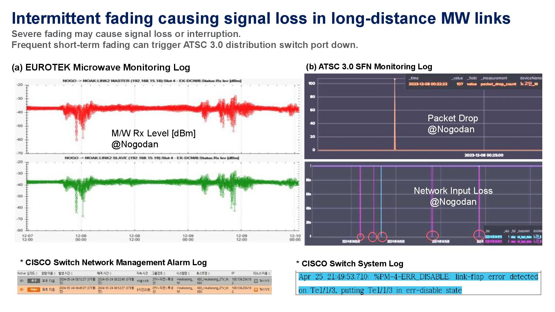
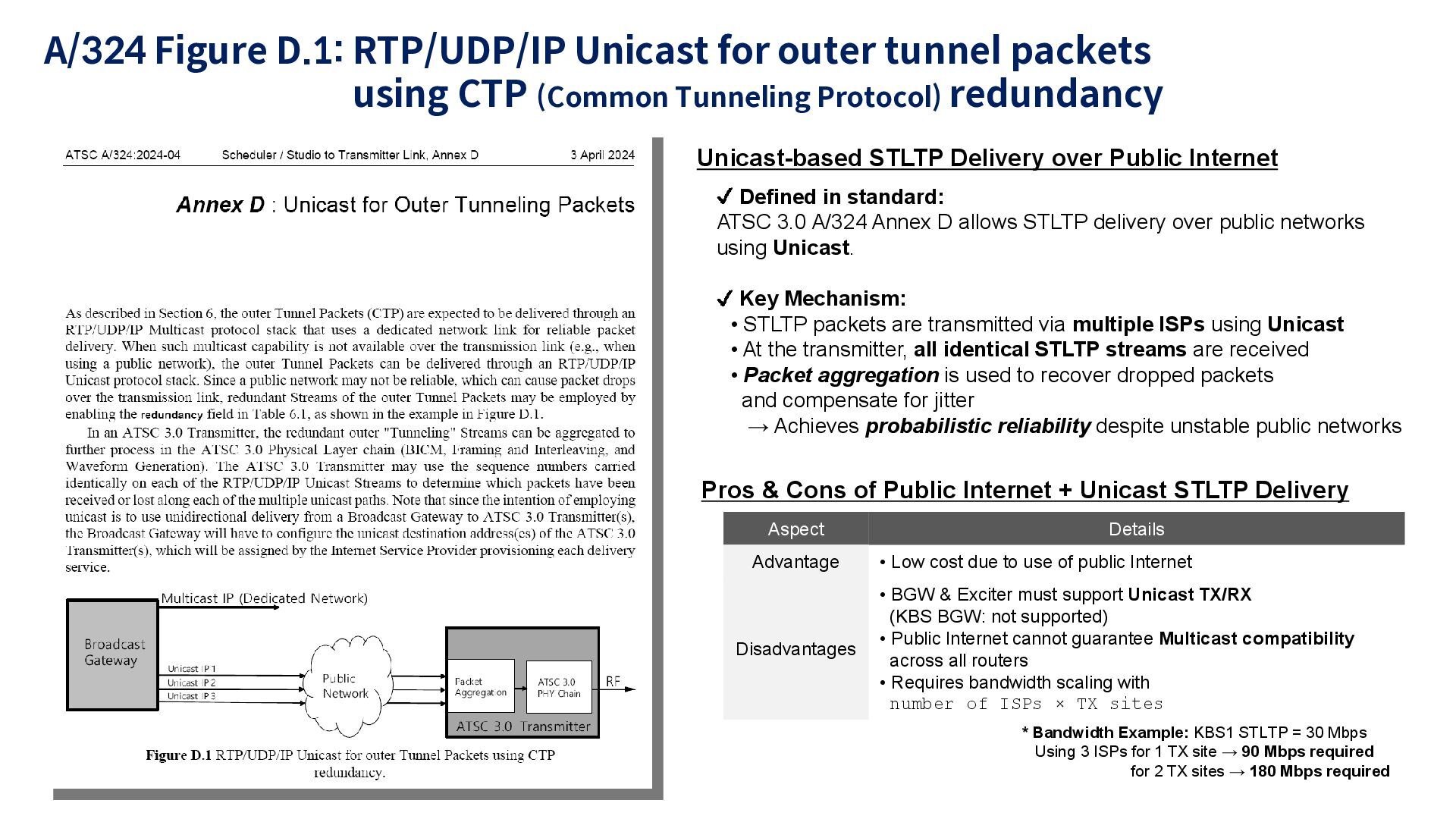
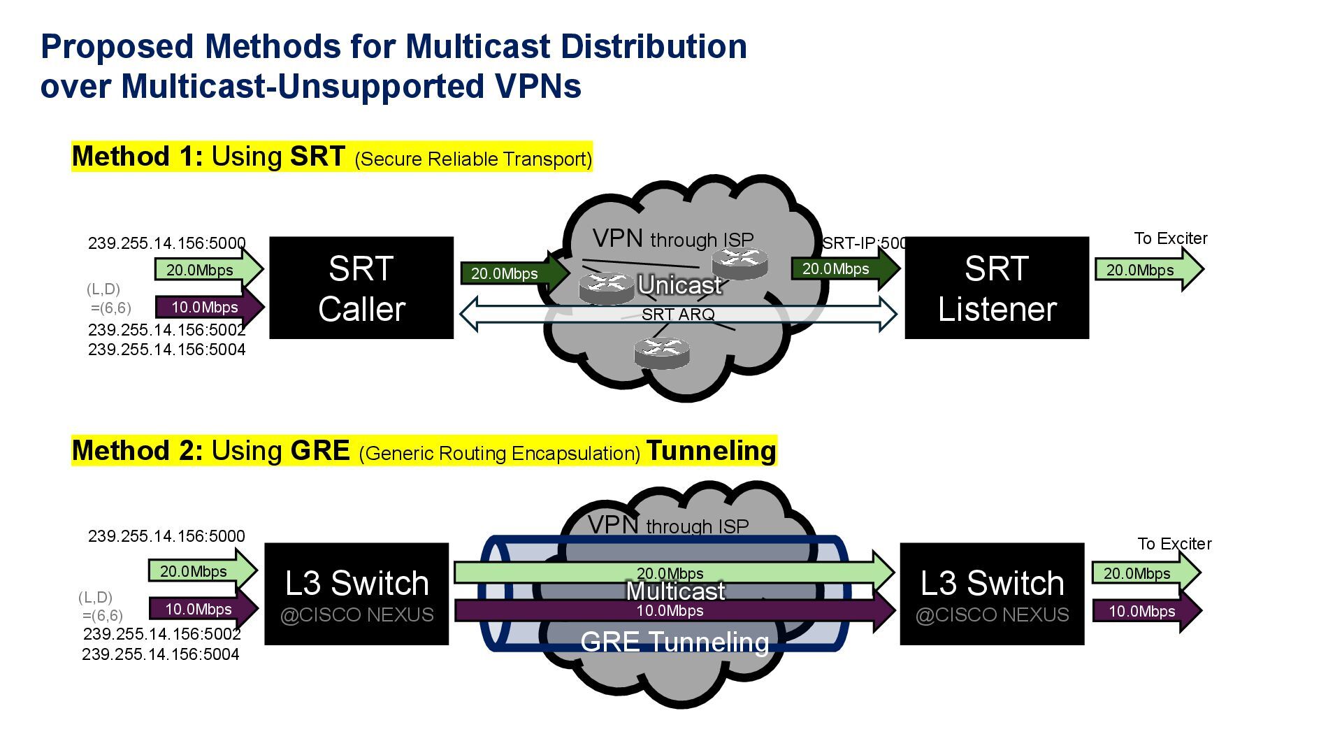
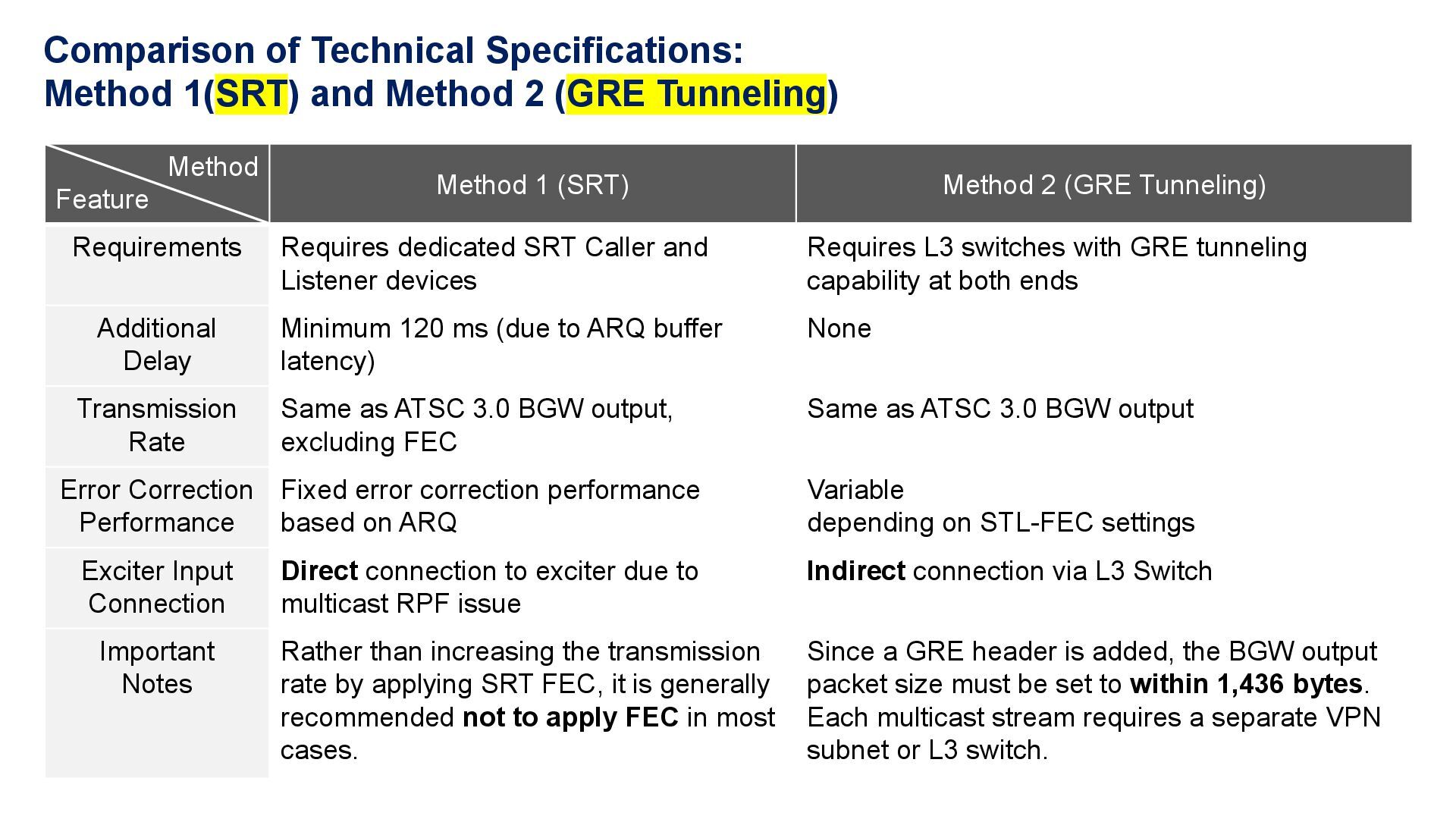
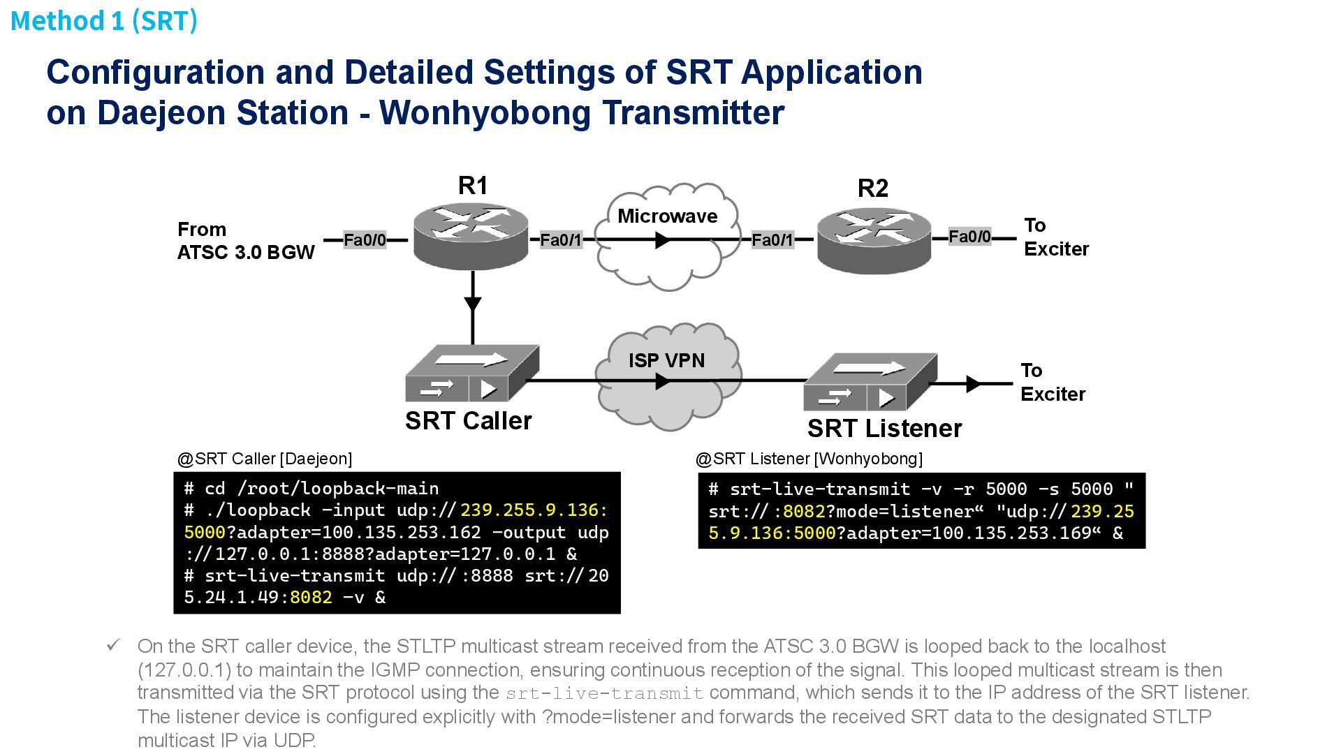
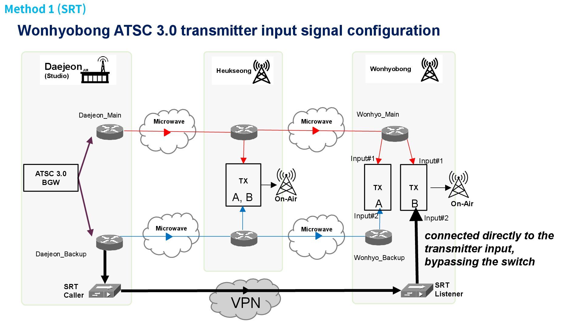
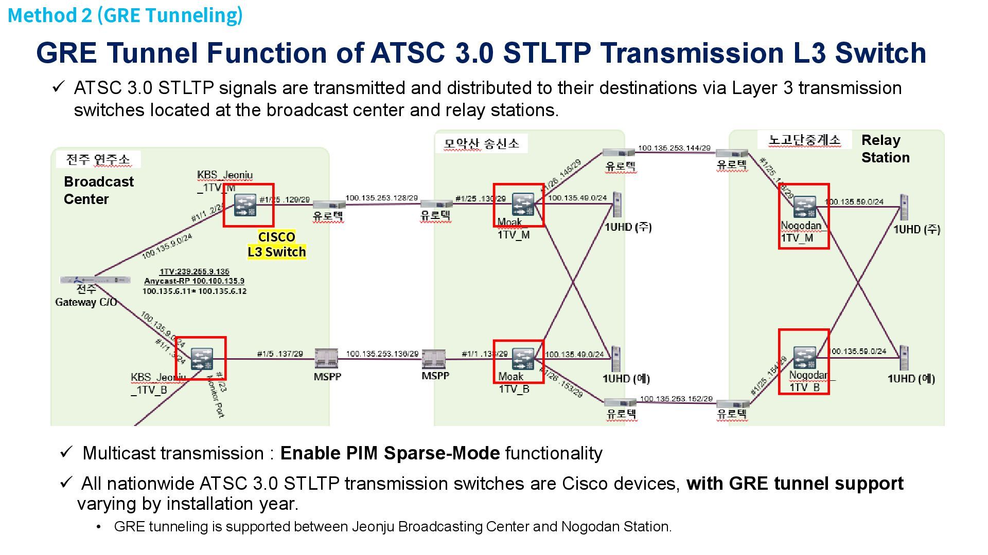
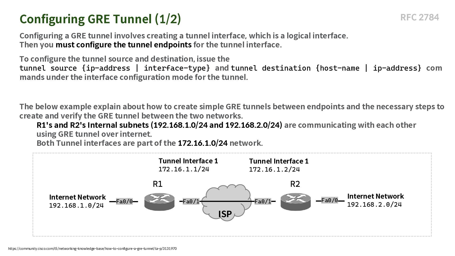
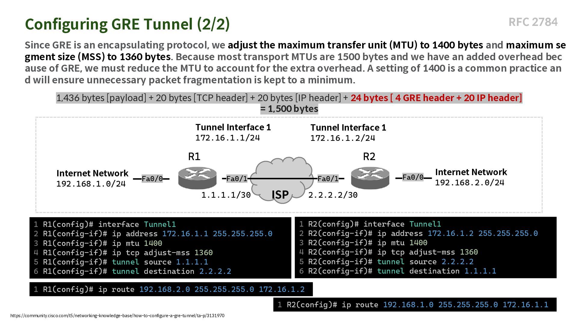
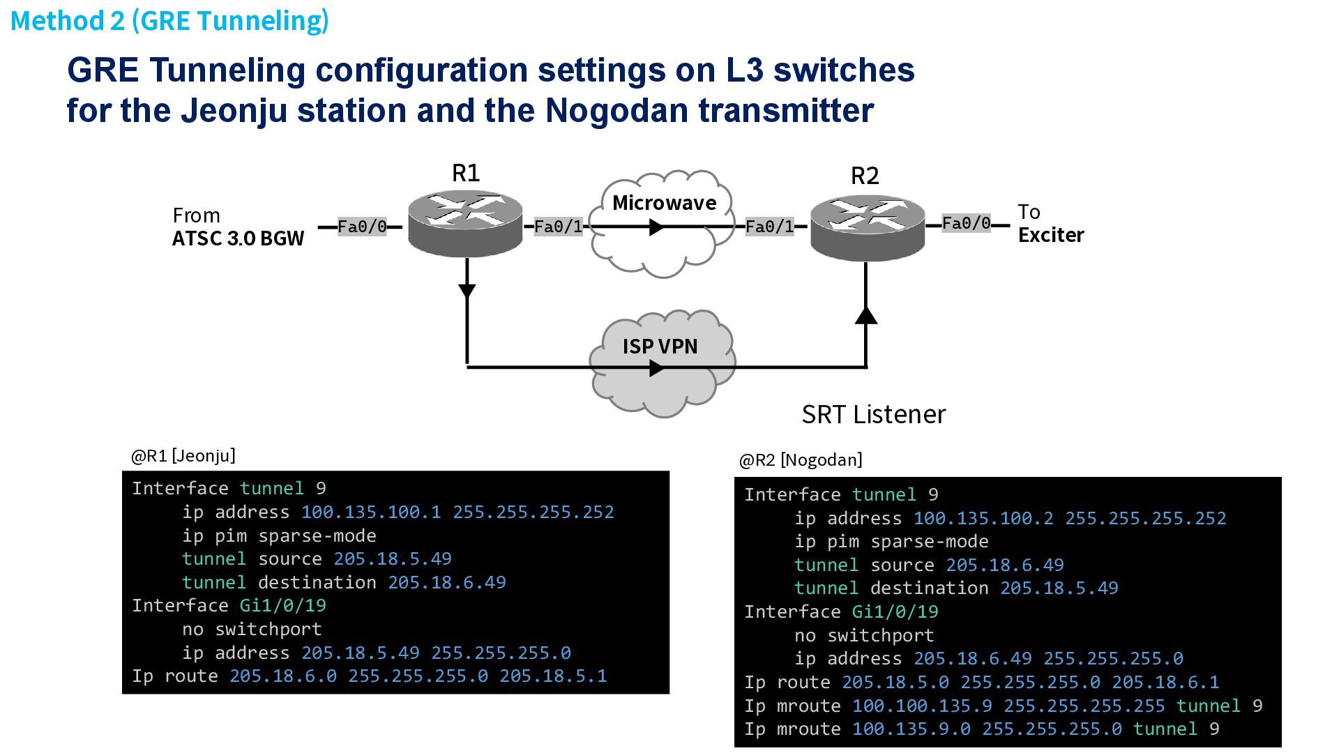
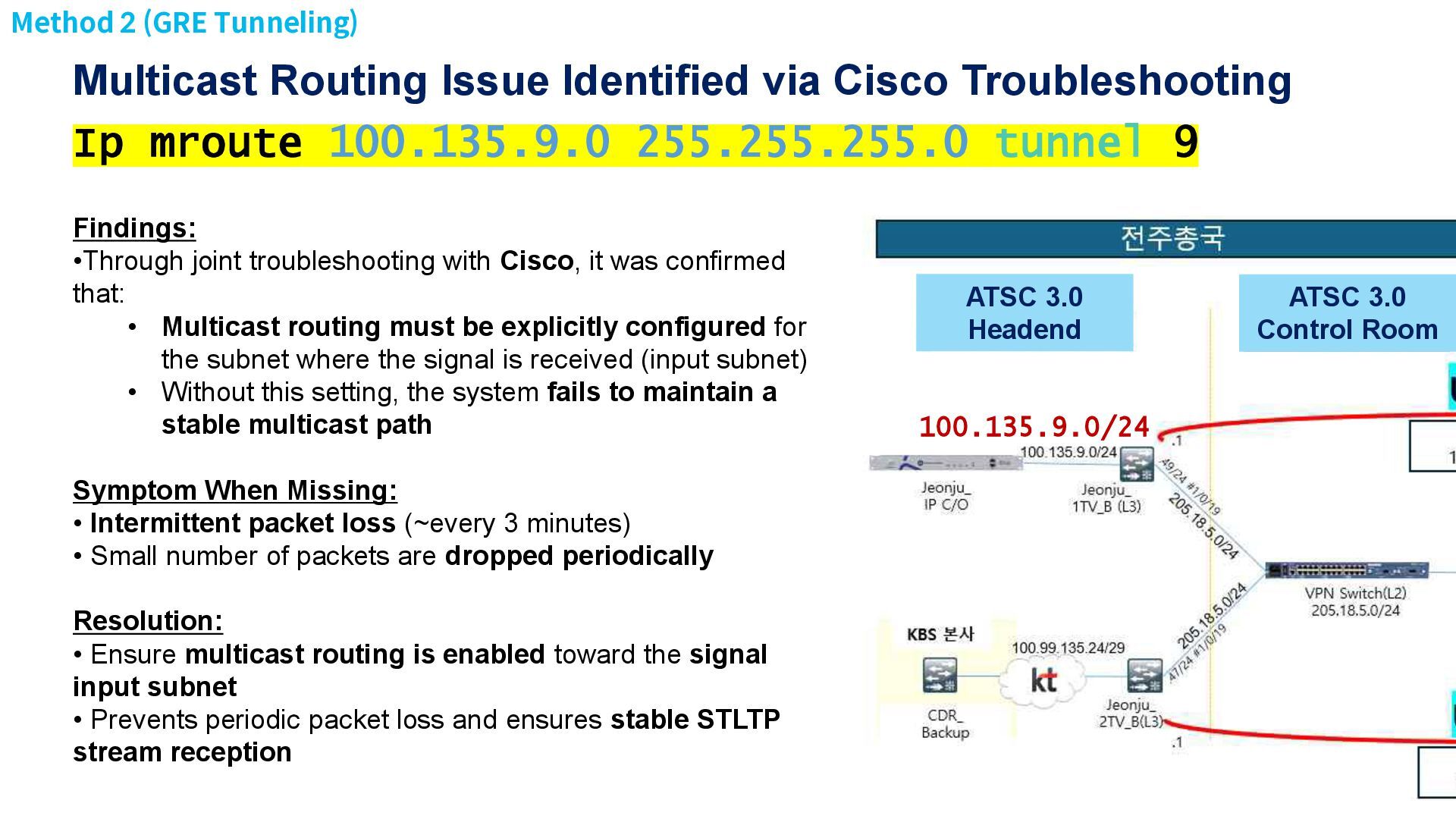
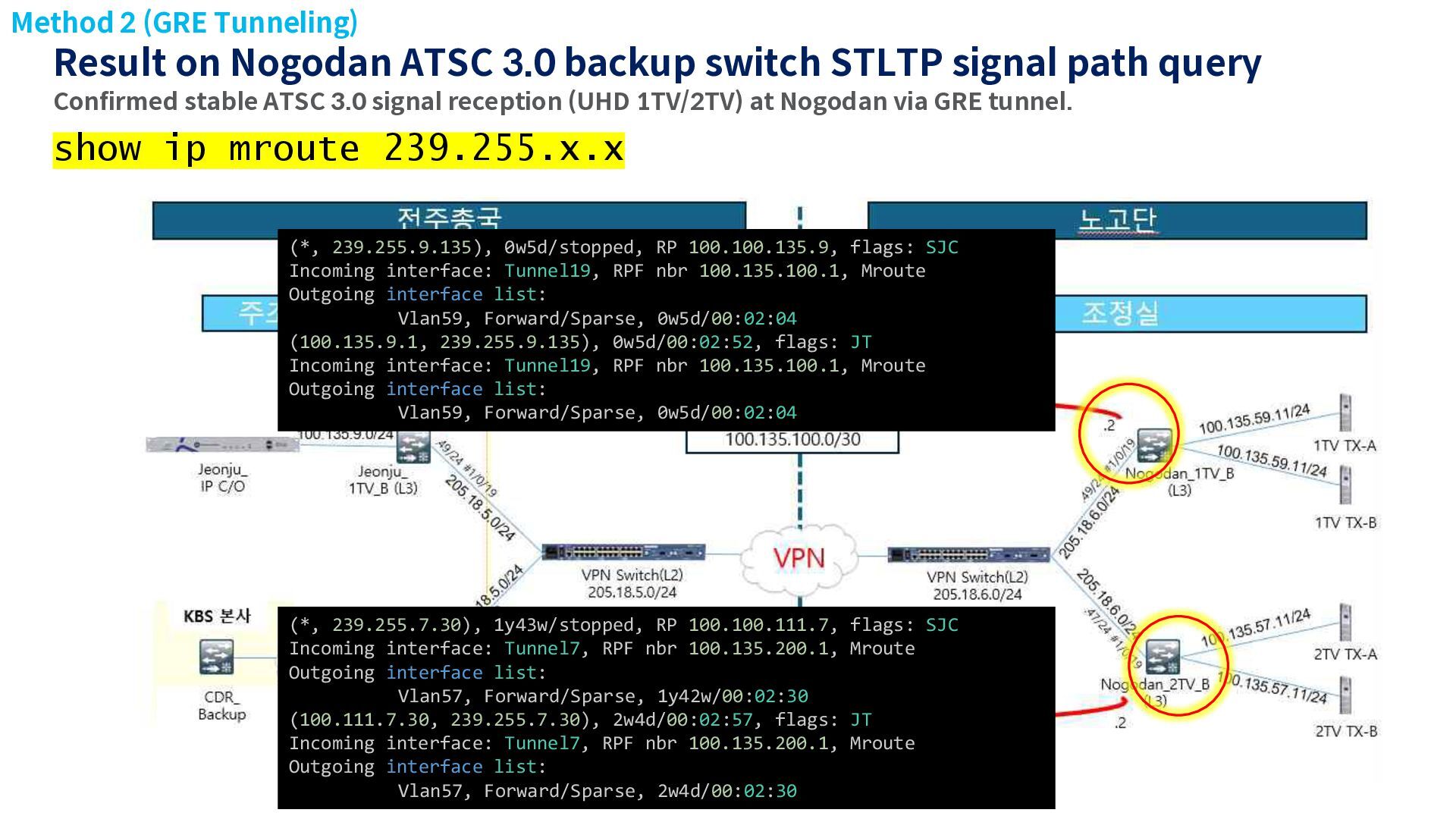
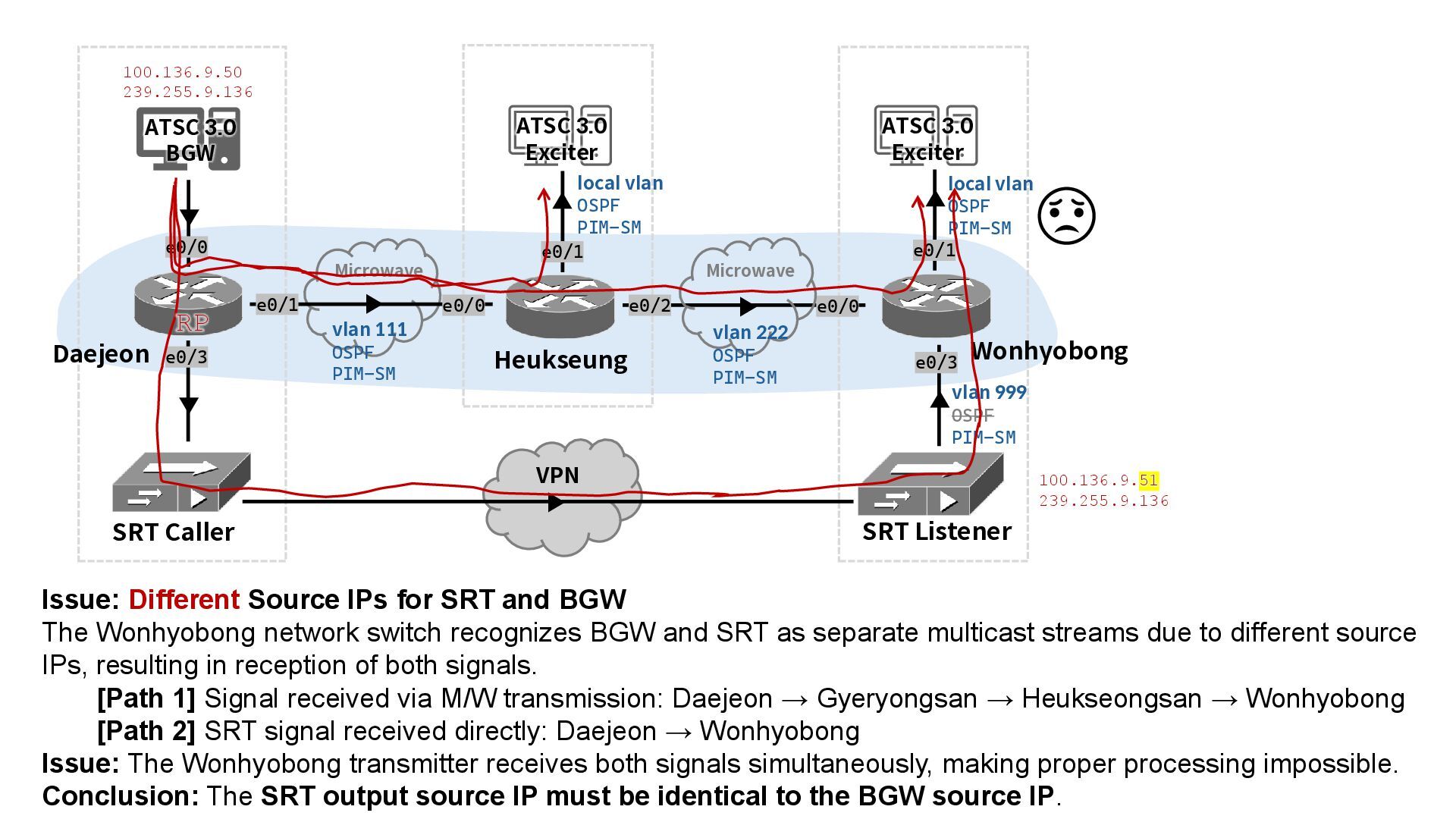
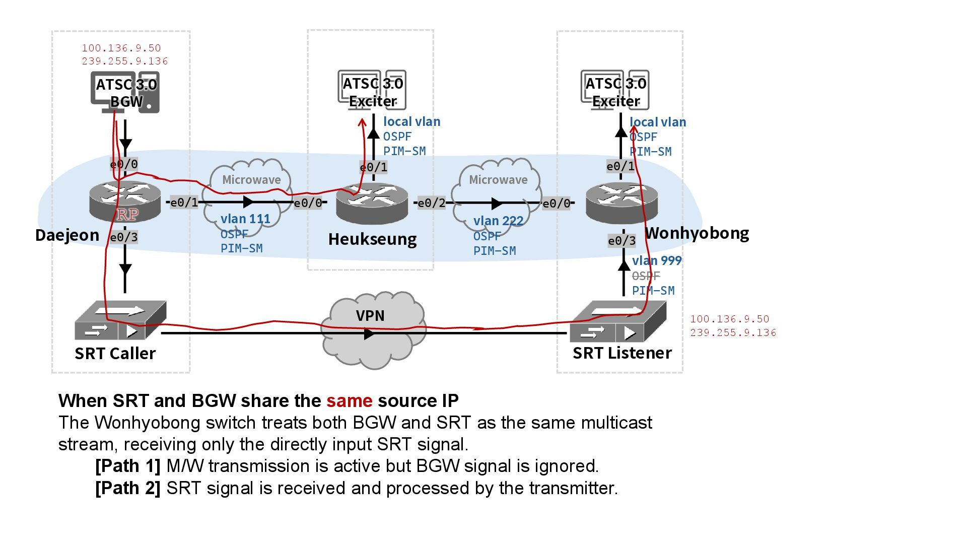
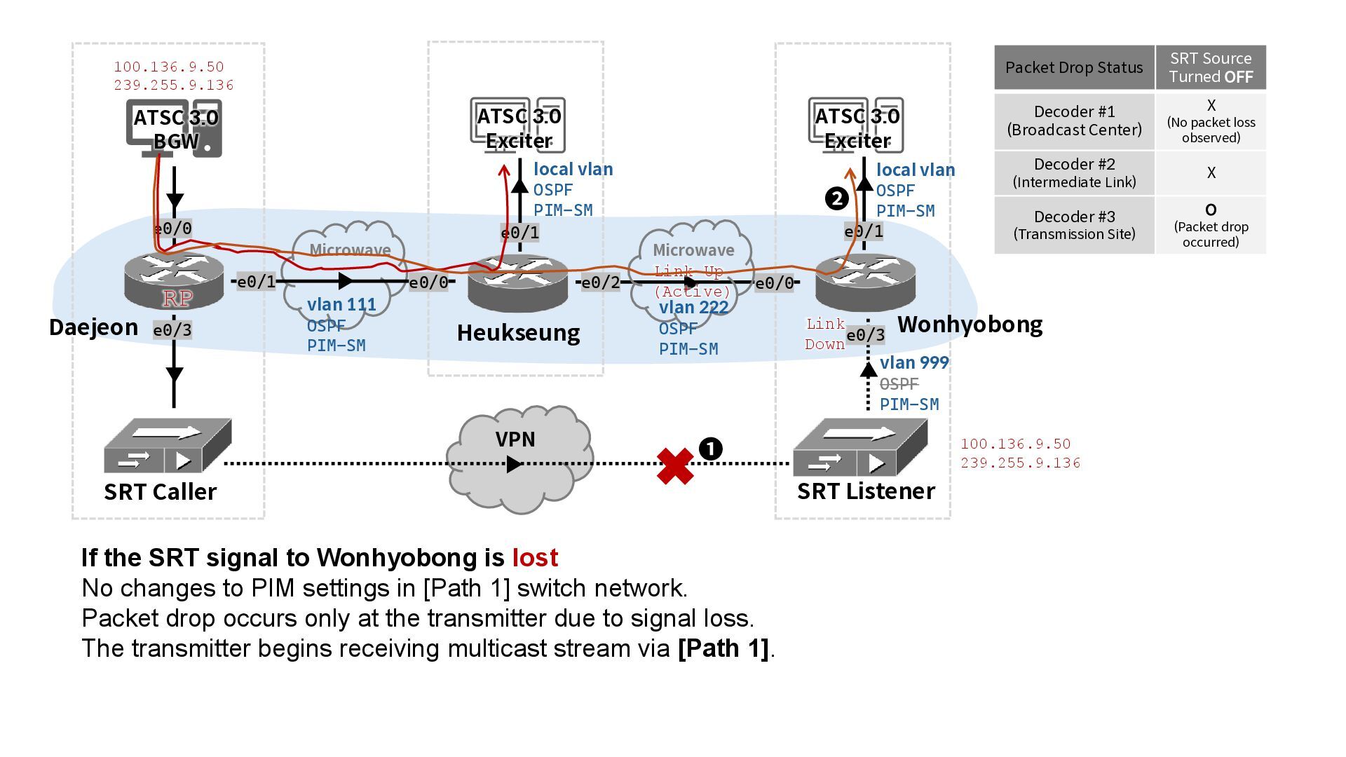
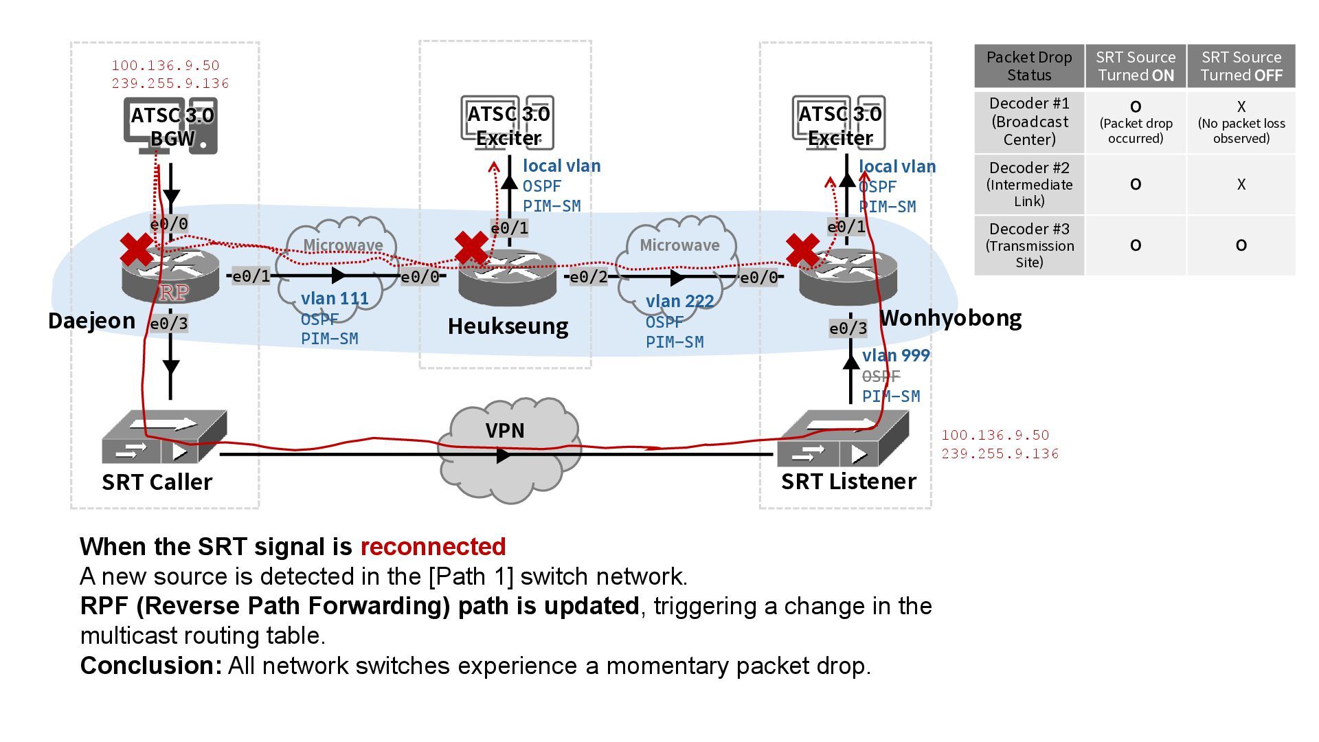
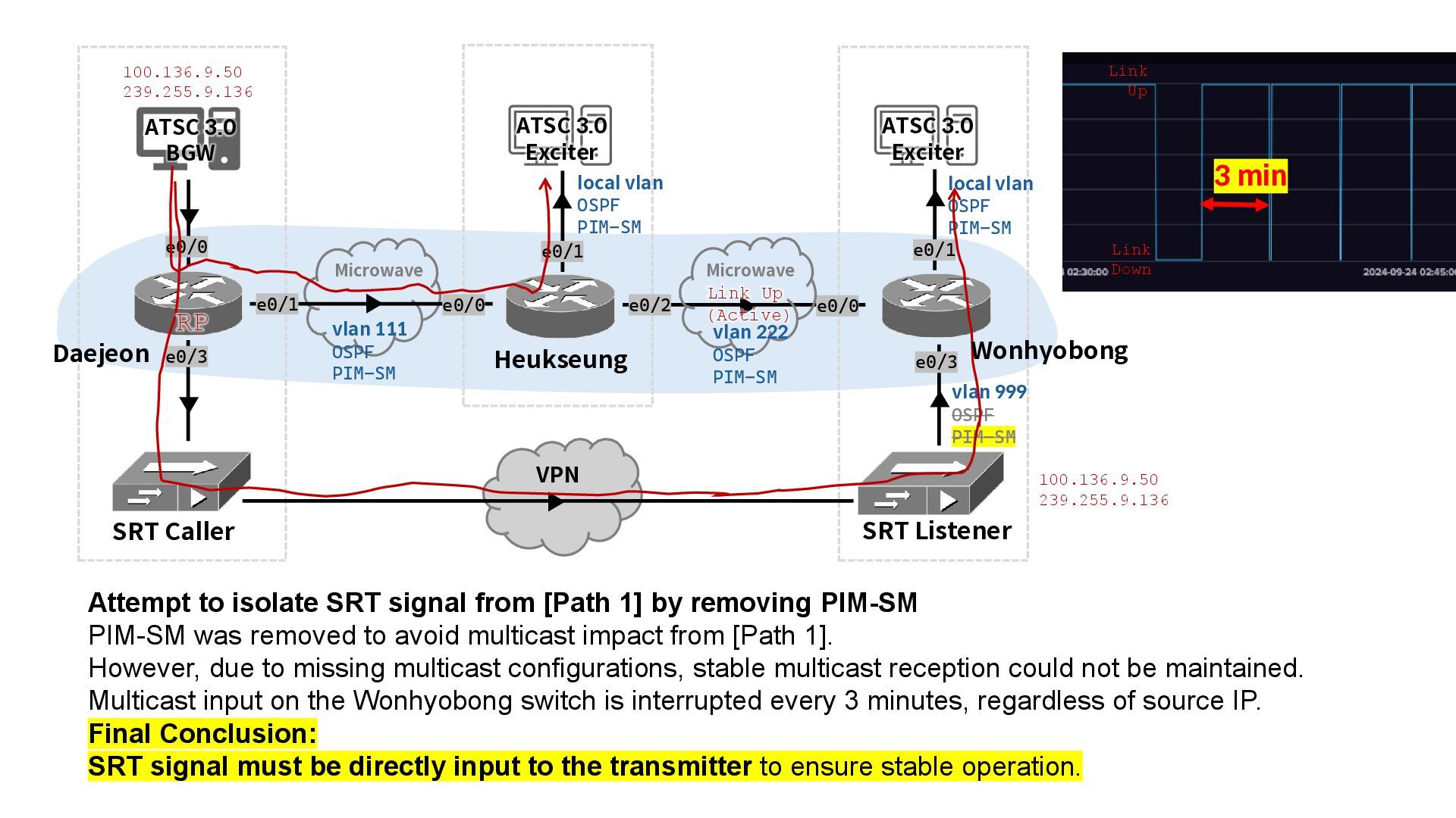
    query Confirmed stable ATSC 3.0 signal reception (UHD 1TV/2TV) at Nogodan via GRE tunnel. show ip mroute 239.255.x.x (*, 239.255.9.135), 0w5d/stopped, RP 100.100.135.9, flags: SJC Incoming interface: Tunnel19, RPF nbr 100.135.100.1, Mroute Outgoing interface list: Vlan59, Forward/Sparse, 0w5d/00:02:04 (100.135.9.1, 239.255.9.135), 0w5d/00:02:52, flags: JT Incoming interface: Tunnel19, RPF nbr 100.135.100.1, Mroute Outgoing interface list: Vlan59, Forward/Sparse, 0w5d/00:02:04 (*, 239.255.7.30), 1y43w/stopped, RP 100.100.111.7, flags: SJC Incoming interface: Tunnel7, RPF nbr 100.135.200.1, Mroute Outgoing interface list: Vlan57, Forward/Sparse, 1y42w/00:02:30 (100.111.7.30, 239.255.7.30), 2w4d/00:02:57, flags: JT Incoming interface: Tunnel7, RPF nbr 100.135.200.1, Mroute Outgoing interface list: Vlan57, Forward/Sparse, 2w4d/00:02:30 Method 2 (GRE Tunneling)
  23. Method 2(GRE Tunneling) Nogodan ATSC 3.0 transmitter input signal configuration

    Unlike the SRT method (Method 1), the GRE tunnel allows the receiver-side switch to accept the multicast signal directly. In case of tunnel failure, the system automatically switches back to the original transmission path, offering seamless failover capabilities.
  24. (b) Nogodan Relay Station KBS 2TV Transmitter TX-B after applying

    GRE tunneling Nogodan ATSC 3.0 transmitter input signal configuration (a) Telecom provider’s VPN traffic management control dashboard. The output is confirmed to be approximately 27 Mbps per channel, which matches the ATSC 3.0 BGW output Input#2 status SFN Delay measurement The STL-FEC configuration set at the ATSC BGW has been verified as applied correctly. Signal reception confirmed without any additional latency. Method 2(GRE Tunneling)
  25. Conclusion • Study Overview • Validated stable transmission of STLTP

    signals over ISP-provided VPN • Proposed SRT and GRE Tunneling techniques • Conducted long-term real-world deployment • Key Results • ATSC 3.0 transmitter, decoder, KBS nationwide SFN monitoring system, and other broadcasting equipment successfully received and processed signals without issues • Supplemented existing microwave (M/W) transmission network, improving stability and reliability of ATSC 3.0 broadcasting • Expected Benefits • Potential to apply SRT and GRE Tunneling to other transmission sections affected by microwave fading and new ATSC 3.0 facilities • Enables low-cost ATSC 3.0 signal transmission via VPN in low-power TV repeater (TVR) areas without M/W networks • Opportunity to replace dedicated IP transmission lines, reducing operational costs for broadcasters
  26. Q1. Why Was the Heukseongsan–Wonhyobong Path Not Used Instead of

    the Daejeon–Wonhyobong Path for the GRE Tunnel? Q2. Why SRT and GRE Tunnel Have Different Input Configurations at the Transmitter (Exciter)? Q3. Multicast Tutorials: Source Tree and Shared Tree RPF (Reverse Path Forwarding) Check
  27. Q1. Why Was the Heukseongsan–Wonhyobong Path Not Used Instead of

    the Daejeon–Wonhyobong Path for the GRE Tunnel? VPN Reliability Concerns at Transmitter Sites Transmitter sites (such as Wonhyobong) share limited telecom infrastructure with nearby government facilities. Due to concerns about VPN stability and reliability, a policy decision was made to avoid VPN-based GRE tunneling between transmitter sites. Result: GRE over VPN between Heukseongsan and Wonhyobong was considered unreliable and therefore not selected as the preferred path.
  28. GRE Tunneling configuration @ Nogodan SRT configuration @ Wonhyobong Q2.

    Why SRT and GRE Tunnel Have Different Input Configurations at the Transmitter (Exciter)?
  29. vlan 111 OSPF PIM-SM Daejeon Heukseung e0/1 e0/0 e0/2 e0/0

    ATSC 3.0 BGW ATSC 3.0 Exciter ATSC 3.0 Exciter e0/1 e0/1 VPN SRT Caller SRT Listener Microwave Microwave e0/3 Wonhyobong local vlan OSPF PIM-SM vlan 222 OSPF PIM-SM local vlan OSPF PIM-SM vlan 999 OSPF PIM-SM e0/3 e0/0 100.136.9.50 239.255.9.136 100.136.9.51 239.255.9.136 Issue: Different Source IPs for SRT and BGW The Wonhyobong network switch recognizes BGW and SRT as separate multicast streams due to different source IPs, resulting in reception of both signals. [Path 1] Signal received via M/W transmission: Daejeon → Gyeryongsan → Heukseongsan → Wonhyobong [Path 2] SRT signal received directly: Daejeon → Wonhyobong Issue: The Wonhyobong transmitter receives both signals simultaneously, making proper processing impossible. Conclusion: The SRT output source IP must be identical to the BGW source IP. RP
  30. vlan 111 OSPF PIM-SM e0/1 e0/0 e0/2 e0/0 ATSC 3.0

    BGW ATSC 3.0 Exciter ATSC 3.0 Exciter e0/1 e0/1 VPN SRT Caller SRT Listener Microwave Microwave e0/3 local vlan OSPF PIM-SM vlan 222 OSPF PIM-SM local vlan OSPF PIM-SM vlan 999 OSPF PIM-SM e0/3 e0/0 100.136.9.50 239.255.9.136 100.136.9.50 239.255.9.136 When SRT and BGW share the same source IP The Wonhyobong switch treats both BGW and SRT as the same multicast stream, receiving only the directly input SRT signal. [Path 1] M/W transmission is active but BGW signal is ignored. [Path 2] SRT signal is received and processed by the transmitter. RP Daejeon Heukseung Wonhyobong
  31. vlan 111 OSPF PIM-SM e0/1 e0/0 e0/2 e0/0 ATSC 3.0

    BGW ATSC 3.0 Exciter ATSC 3.0 Exciter e0/1 e0/1 VPN SRT Caller SRT Listener Microwave Microwave e0/3 local vlan OSPF PIM-SM vlan 222 OSPF PIM-SM local vlan OSPF PIM-SM vlan 999 OSPF PIM-SM e0/3 e0/0 100.136.9.50 239.255.9.136 100.136.9.50 239.255.9.136 If the SRT signal to Wonhyobong is lost No changes to PIM settings in [Path 1] switch network. Packet drop occurs only at the transmitter due to signal loss. The transmitter begins receiving multicast stream via [Path 1]. Link Up (Active) RP Packet Drop Status SRT Source Turned OFF Decoder #1 (Broadcast Center) X (No packet loss observed) Decoder #2 (Intermediate Link) X Decoder #3 (Transmission Site) O (Packet drop occurred) Link Down ❷ ❶ Daejeon Heukseung Wonhyobong
  32. vlan 111 OSPF PIM-SM e0/1 e0/0 e0/2 e0/0 ATSC 3.0

    BGW ATSC 3.0 Exciter ATSC 3.0 Exciter e0/1 e0/1 VPN SRT Caller SRT Listener Microwave Microwave e0/3 local vlan OSPF PIM-SM vlan 222 OSPF PIM-SM local vlan OSPF PIM-SM vlan 999 OSPF PIM-SM e0/3 e0/0 100.136.9.50 239.255.9.136 100.136.9.50 239.255.9.136 When the SRT signal is reconnected A new source is detected in the [Path 1] switch network. RPF (Reverse Path Forwarding) path is updated, triggering a change in the multicast routing table. Conclusion: All network switches experience a momentary packet drop. RP Packet Drop Status SRT Source Turned ON SRT Source Turned OFF Decoder #1 (Broadcast Center) O (Packet drop occurred) X (No packet loss observed) Decoder #2 (Intermediate Link) O X Decoder #3 (Transmission Site) O O Daejeon Heukseung Wonhyobong
  33. vlan 111 OSPF PIM-SM e0/1 e0/0 e0/2 e0/0 ATSC 3.0

    BGW ATSC 3.0 Exciter ATSC 3.0 Exciter e0/1 e0/1 VPN SRT Caller SRT Listener Microwave Microwave e0/3 local vlan OSPF PIM-SM vlan 222 OSPF PIM-SM local vlan OSPF PIM-SM vlan 999 OSPF PIM-SM e0/3 e0/0 100.136.9.50 239.255.9.136 100.136.9.50 239.255.9.136 Attempt to isolate SRT signal from [Path 1] by removing PIM-SM PIM-SM was removed to avoid multicast impact from [Path 1]. However, due to missing multicast configurations, stable multicast reception could not be maintained. Multicast input on the Wonhyobong switch is interrupted every 3 minutes, regardless of source IP. Final Conclusion: SRT signal must be directly input to the transmitter to ensure stable operation. Link Up (Active) RP 3 min Link Down Link Up Daejeon Heukseung Wonhyobong
  34. Q3. Multicast Tutorials: Source Tree and Shared Tree (1/2) Multicast

    packets are delivered through two types of trees: Source Tree and Shared Tree. Source Tree ✓ A routing path that connects the multicast source to the receiver using the shortest path. ✓ Also called SPT (Shortest Path Tree). ✓ PIM-DM (Dense Mode) uses the Source Tree for packet delivery. Note: PIM-SSM uses only Source Trees. Bidir-PIM uses only Shared Trees. Multicast Server R2 R4 R3 (RP) Host (1.1.12.1, 239.1.1.1)
  35. Q3. Multicast Tutorials: Source Tree and Shared Tree (1/2) Multicast

    packets are delivered through two types of trees: Source Tree and Shared Tree. Shared Tree ✓ A routing path that goes through a central router called the RP (Rendezvous Point). ✓ Also known as RPT (Rendezvous Point Tree). ✓ The RP acts as a registration point for multicast sources. ✓ In PIM-SM (Sparse Mode), the first packet is sent via the Shared Tree, and then subsequent packets are switched to the Source Tree. Multicast Server R2 R4 R3 (RP) Host (1.1.12.1, 239.1.1.1)
  36. Q3. Multicast Tutorials: RPF (Reverse Path Forwarding) Check Before setting

    up a multicast network, a unicast routing protocol must be in place. This is essential to prevent multicast packet loops. ✓ To avoid loops, multicast routing uses a process called RPF (Reverse Path Forwarding) check. ✓ RPF requires a working unicast routing table. Multicast Server R2 R4 R3 Host (1.1.12.1, 239.1.1.1) F0/0.24 F0/0.34 1.1.12.0/24 F0/0.24 Unlike unicast routing, which forwards packets based on the destination IP, multicast routing first checks the source IP using RPF, then forwards the packet based on the destination group address.