sense of gratitude to Mr. Manoj Rajpal and Mr. Sumit Chugh, who directed and guided me with their timely advice and constant inspiration which eased the task of completing this training and project report. I will like to give special mention to my fellow trainee and also like to thank the entire employee and other members of Hindustan Coca Cola Beverages Pvt Ltd, Gurgaon for their support. Finally I must say that no height is ever achieved without some sacrifice made at some end and it is here that I owe my special debt to my parents and family members for showing their love throughout this entire period of time.
– centre operation and Call management System is a database, administration, and reporting web application to help businesses in their technical support and take immediate action to solve them. It’s an interface so that a client can log their calls and helpdesk assign the calls to the particular department and employee of the department will solve the problem and will give notification to the client regarding its solution.
System: First, let us narrate our thinking about the project, which we are going to propose. It’s an interface so that a client can log their calls and helpdesk assign the calls to the particular department and employee of the department will solve the problem and will give notification to the client regarding its solution. Some of the most important work that the Website we are going to propose performs is as follows: 1. The main objective of the project is to develop a Website that would be simple, easy-to-use, and user- friendly, in order to our busy life where we do have less time to accomplish a job. 2. It comprises from registering of new user to the validation of existing customer. 3. A person can easily create his/her account and make use of the site in just a moment of time. 4. The Website provides the user to make a call for his/her technical problem. 5. The Website also provides the Administrator to insert, update and delete records. 6. The admin will take the call and can able to provide solutions to customer. 7. Secure information stored in the databases in some fashion in order to provide security. The Website we are about to propose allows a user/admin to login with his/her own user id and password, and easy access to their profiles. Salient features of Call Management System: After Login, Administrator can view calls details, view users having registered in the site, can able to provide solutions, and can delete the user from the database. After Login, a user can log his/her call to the website. Every stage data is stored in the database after checking and testing. This is why the system is very easy to use and every user can accept the system by thinking its utility in present and by applying the idea of Iterative Water Fall Model the system can be developed with more features in future. Secure information stored in the databases in some fashion in order to provide security. This project can be further developing with some more facilities. Scope: Main objectives of this website are to develop an interface so that user can log a call and they will get their solution with in response.
and back ends (c#.net and SQL Server Express respectively) are made using Microsoft Visual Studio. Microsoft Visual Studio.NET: Visual Studio.Net is the tool for rapidly building enterprise–scale ASP Web applications and high performance desktop applications. Visual Studio includes component–based development tools, such as Visual C#, Visual Basic, Visual C++, as well as a number of additional technologies to simplify team- based design, development and deployment of our solutions. Visual Studio supports .Net framework, which provides a common language runtime and unified programming classes. The biggest facility of ASP.Net is everything is object-oriented. All aspects of OOP are implemented in ASP.Net and we can also create multithreaded applications in ASP.Net. Also included in it is the MSDN Library, which contains all the documentation for these development tools. From Visual Basic 1.0, which radically simplified writing Windows Applications, to Visual Basic 4.0, which helped to establish COM2 as the standard Windows object architecture, the VB language has been a cornerstone of the Windows platform for nearly a decade. Now, as applications are evolving from a standalone executable sitting on a user’s hard drive to a distributed application delivered by the Web server across the Internet, Microsoft is expanding away from simply providing an operating system: Microsoft is providing XML web services as well. A key part of Microsoft’s thrust into this new XML web services space is the .Net Framework, designed from the ground up to allow developers to write and deploy complex Web applications easily. ASP.Net is the pillar of the .Net Framework, and yet another step forward in evolution of the language. It is a high level programming language for the .net Framework, and provides the easiest point of entry to the Microsoft .Net platform. The .NET Framework: The .Net Framework is a new computing platform that simplifies application development in the highly distributed environment of the Internet. It is design to fulfil the following objectives: To provide a consistent object-oriented programming environment whether object code is stored and executed locally but Internet-distributed or executed remotely. To provide a code-execution environment that minimizes software deployment and versioning conflicts. To provide a code-execution environment that guarantees safe execution of code, including code created by an unknown o semi-trusted third party. To provide a code-execution environment that eliminates the performance problems of scripted or interpreted environments. To make the developer experiences consistent across widely varying types of applications, such as Windows-based applications and Web-based application. To build all communication on industry standards to ensure that code based on the .Net Framework can integrate with any other code
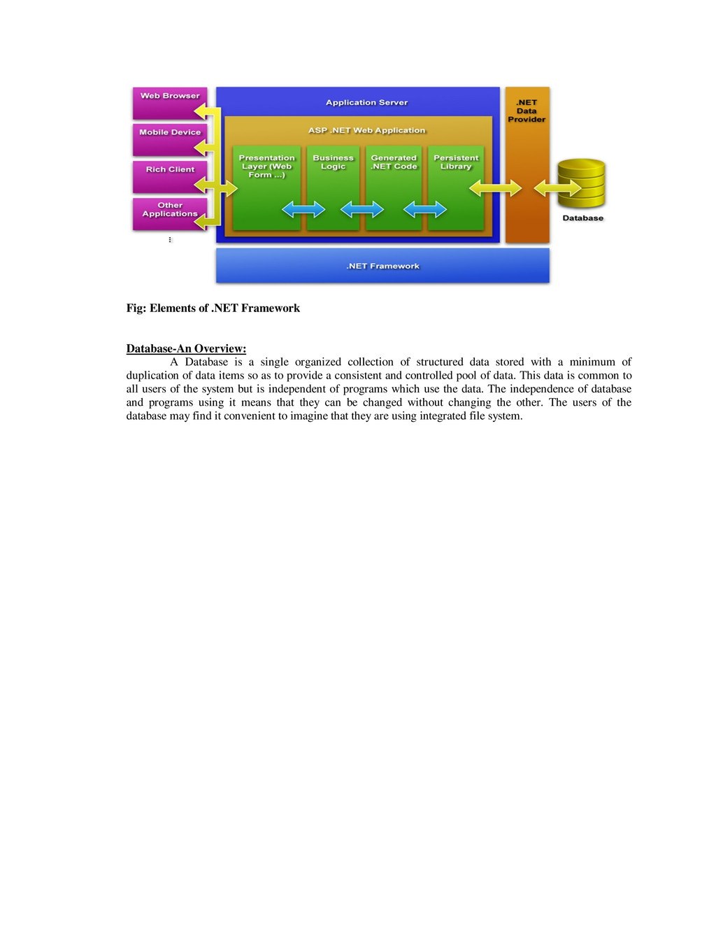
a single organized collection of structured data stored with a minimum of duplication of data items so as to provide a consistent and controlled pool of data. This data is common to all users of the system but is independent of programs which use the data. The independence of database and programs using it means that they can be changed without changing the other. The users of the database may find it convenient to imagine that they are using integrated file system.
of a proposal designed to determine the difficulty in carrying out a designated task. Generally, a feasibility study precedes technical development and project implementation. In other words, a feasibility study is an evaluation or analysis of the potential impact of a proposed project. The feasibility study is the important step in any software development process. This is because it makes analysis of different aspects like cost required for developing and executing the system, the time required for each phase of the system and so on. If these important factors are not analyzed then definitely it would have impact on the organization and the development and the system would be a total failure. Steps in feasibility analysis Eight steps involved in the feasibility analysis are: Form a project team and appoint a project leader. Prepare system flowcharts. Enumerate potential proposed system. Define and identify characteristics of proposed system. Determine and evaluate performance and cost effective of each proposed system. Weight system performance and cost data. Select the best-proposed system. Prepare and report final project directive to management. Feasibility Study Division: Four key considerations are involved in the feasibility analysis: Technical Feasibility: It specifies whether the proposed solution in the project is possible to b Implemented using available hardware and software. Economical Feasibility: This defines the measurement cost effectiveness of the project. It further consists of two parts : a. Direct cost and b. Indirect cost Operational Feasibility: Operational feasibility considers the factors that how the software will satisfy the need of the users, how it could be changed for future requirements and the operational factors of the computer. Schedule Feasibility: Time evolution is most important considerations in the development of project. The time schedule required for the development time effect machine time, cost and cause delay in the development other systems.
intensified our attention on some following paths before doing this project. An abstract definition on the purpose of the project. Formulation of different strategies for the completion of project Examination and evaluation of alternative strategies or solution of the project by using optimum resource and minimum usage cost and time. A cost benefit analysis is done to determine whether the solution is the best possible way to get desired output, or the selected strategy is not feasible as for high cost, resource constraints or any other technical reason. The output of all the above empowered us to determine the best possible way to implement the project setting the project goal, bounds like part of the existing system that cannot be changed, resources available and its limitation, funds that can be incurred, personnel available for the project.
PURPOSE OF THE SYSTEM A call management system is a centralized office used for the purpose of receiving and transmitting a large volume of request by its web interface. A call management system is operated by a company to administer incoming technical support or information inquires from consumers. Outgoing calls for telemarketing, clientele, product services, and debt collection are also made. In addition to a call management system, a user can log his call for any technical support whether it is hardware or software support and they will get solutions for their logged call in a given specific time. Most major businesses use call management system to interact with their customers. Examples include utility companies, mail order catalog retailers, and customer support for computer hardware and software. Some businesses even service internal functions through call management system. Examples of this include help desks, technical support executive (for Hardware, Software, Network, Security). PROBLEMS IN THE EXISTING SYSTEM The existing system is a manual system. Here the employees needs to save the information in the form of excel sheets or Disk Drives. There is no sharing is possible if the data is in the form of paper or Disk drives. The manual system gives us very less security for saving data; some data may be lost due to mismanagement. It’s a limited system and fewer users friendly. Searching of particular information is very critical it takes lot of time. It is very critical to maintain manually call records of customers, because call management system receives huge no of calls per a day. It is a tedious job to maintain different customers are asking different service details, normally solve these queries are not possible. Automated system is needed. Every employee having different rosters, different shift timings, manually handle these roster is tough work. Search an employee roster in call management system is a tedious job. SOLUTION OF THESE PROBLEMS The development of this new system contains the following activities, which try to automate the entire process keeping in the view of database integration approach.
controls provided by system Rich User Interface. The system makes the overall project management much easier and flexible. It can be accessed over the Intranet. The user information can be stored in centralized database which can be maintained by the system. This can give the good security for user information because data is not in client machine. Authentication is provided for this application only registered Users can access. There is no risk of data management at any level while the project development is under process. The automated system will provide to the customers for reliable services. The speed and accuracy of this system will improve more and more. STUDY OF THE SYSTEM In the flexibility of uses the interface has been developed a graphics concepts in mind, associated through a browser interface. The GUI’s at the top level has been categorized as follows 1. Administrative User Interface Design 2. The Operational and Generic User Interface Design The administrative user interface concentrates on the consistent information that is practically, part of the organizational activities and which needs proper authentication for the data collection. The Interface helps the administration with all the transactional states like data insertion, data deletion, and data updating along with executive data search capabilities. The operational and generic user interface helps the users upon the system in transactions through the existing data and required services. The operational user interface also helps the ordinary users in managing their own information helps the ordinary users in managing their own information in a customized manner as per the assisted flexibilities. Module Description 1. Administrator 2. Employees 3. Customers 4. Services 5. Employee Rosters Administration Administration is the chief of the Call Management System. He can have all the privileges to do anything in this system. Administrator can register new employees, departments into the system. Admin can keep track team employees and their performance. For every call receive the administration taking
the call management system. Call activity done by administrator. For every call the admin capture the information of call id, date, time, attended employee id, and customer information etc. Employees Here a team employees means they are maintaining the Call management system. The major responsibility for the employees is they have to receive the call from the customer and process the customer queries. The challenging issue is here he can give necessary answers or solutions of customer queries, because different customers are posting various service queries. Customers Customers in the sense of service holders. While using the services the customers have to face any problem then they automatically call to the call management office and find a solution. Services Customer service also known as Client Service is the provision of service to customer before, during and after solution. Customer service is a series of activities designed to enhance to level of customer satisfaction. Here customer services my provided by a call management person. Customer service is an integral part of a company’s customer value proportions. Servicer in the sense of Clarifying the customer doubts Process the customer queries Assign new services and solutions to customers Employee Rosters The maintenance of employee rosters in a call center is a tough job. Every roster has three shifts. Roster has starting date and ending date and an in charge will be there for every roster. Call center employee need to follow their roster and shift. Every roster has holiday also. Admin Can keep track employees rosters and shifts means employees login date and time, log off date and time etc., INPUTS AND OUTPUTS The major inputs and outputs and major functions of the system are follows: Inputs: Admin enter his user id and password for login. User enters his user id and password for login. Admin enter user id or date for track the user login information New users give his completed personnel, address and phone details for registration. Admin gives different kind of user information for search the user data. User gives his user id, hint question, answer for getting the forgotten password. Employee asking customer service details before process the queries. Employees search the customer information while process Outputs: Admin can have his own home page. Users enter their own home page.
database. Admin will get the login information of a particular user. The new user’s data will be stored in the centralized database. Admin get the search details of different criteria. User can get his forgot password. HARDWARE AND SOFTWARE REQUIREMENT Server Operating system like Windows XP, Windows 7, Windows Vista etc. ASP.net, C#. SQL Server Express Client Windows Operationg system Any web browser that Supports java like as Internet Explorer, Mozilla Firefox, and Google chrome. The category of this project is WEB APPLICATION This project is developed using following technologies and software: MS-Office 2007. Internet explorer 8. Mozilla Firebox. Google chrome. Microsoft Visual Studio 2010 SDLC METHDOLOGIES This document play a vital role in the development of life cycle (SDLC) as it describes the complete requirement of the system. It means for use by developers and will be the basic during testing phase. Any changes made to the requirements in the future will have to go through formal change approval process.
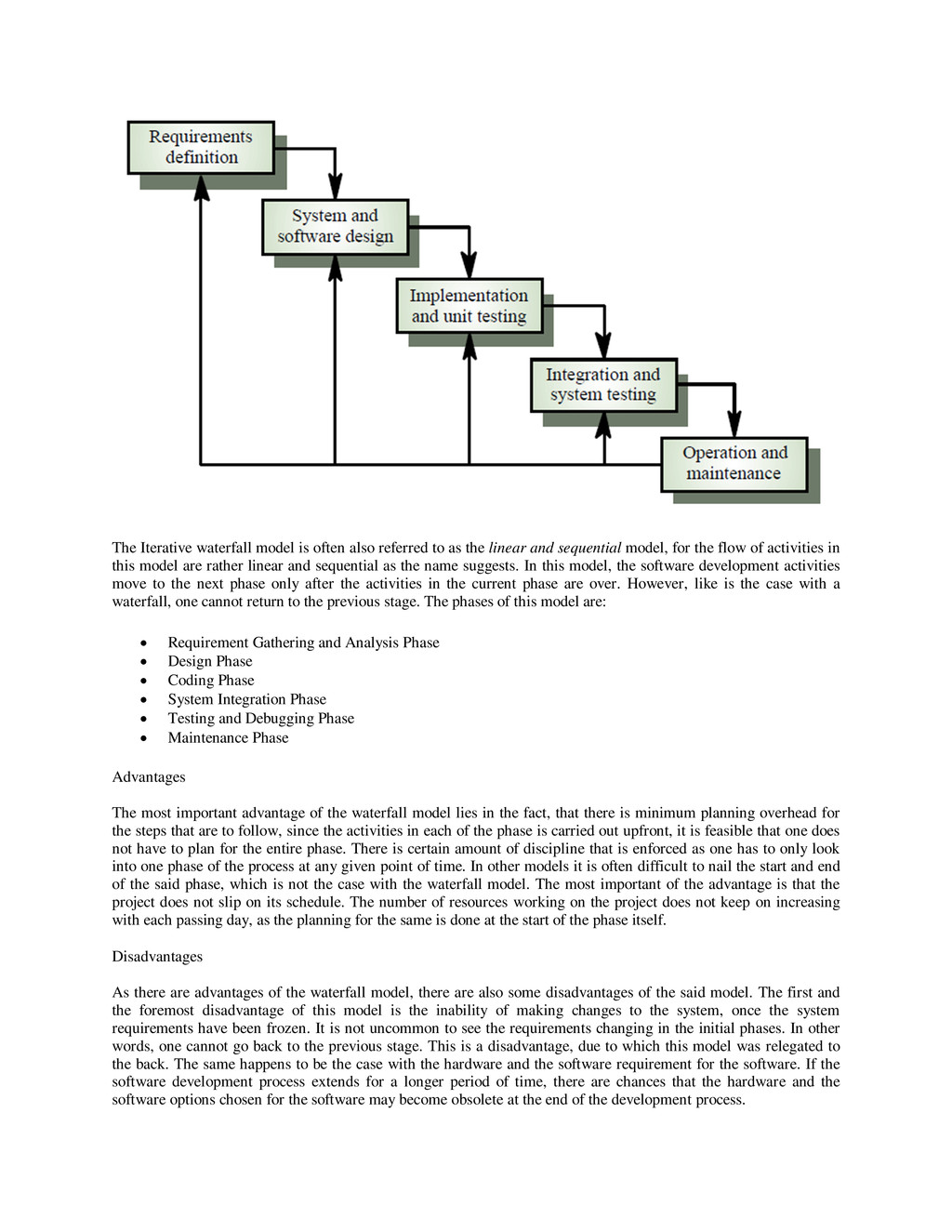
the linear and sequential model, for the flow of activities in this model are rather linear and sequential as the name suggests. In this model, the software development activities move to the next phase only after the activities in the current phase are over. However, like is the case with a waterfall, one cannot return to the previous stage. The phases of this model are: Requirement Gathering and Analysis Phase Design Phase Coding Phase System Integration Phase Testing and Debugging Phase Maintenance Phase Advantages The most important advantage of the waterfall model lies in the fact, that there is minimum planning overhead for the steps that are to follow, since the activities in each of the phase is carried out upfront, it is feasible that one does not have to plan for the entire phase. There is certain amount of discipline that is enforced as one has to only look into one phase of the process at any given point of time. In other models it is often difficult to nail the start and end of the said phase, which is not the case with the waterfall model. The most important of the advantage is that the project does not slip on its schedule. The number of resources working on the project does not keep on increasing with each passing day, as the planning for the same is done at the start of the phase itself. Disadvantages As there are advantages of the waterfall model, there are also some disadvantages of the said model. The first and the foremost disadvantage of this model is the inability of making changes to the system, once the system requirements have been frozen. It is not uncommon to see the requirements changing in the initial phases. In other words, one cannot go back to the previous stage. This is a disadvantage, due to which this model was relegated to the back. The same happens to be the case with the hardware and the software requirement for the software. If the software development process extends for a longer period of time, there are chances that the hardware and the software options chosen for the software may become obsolete at the end of the development process.
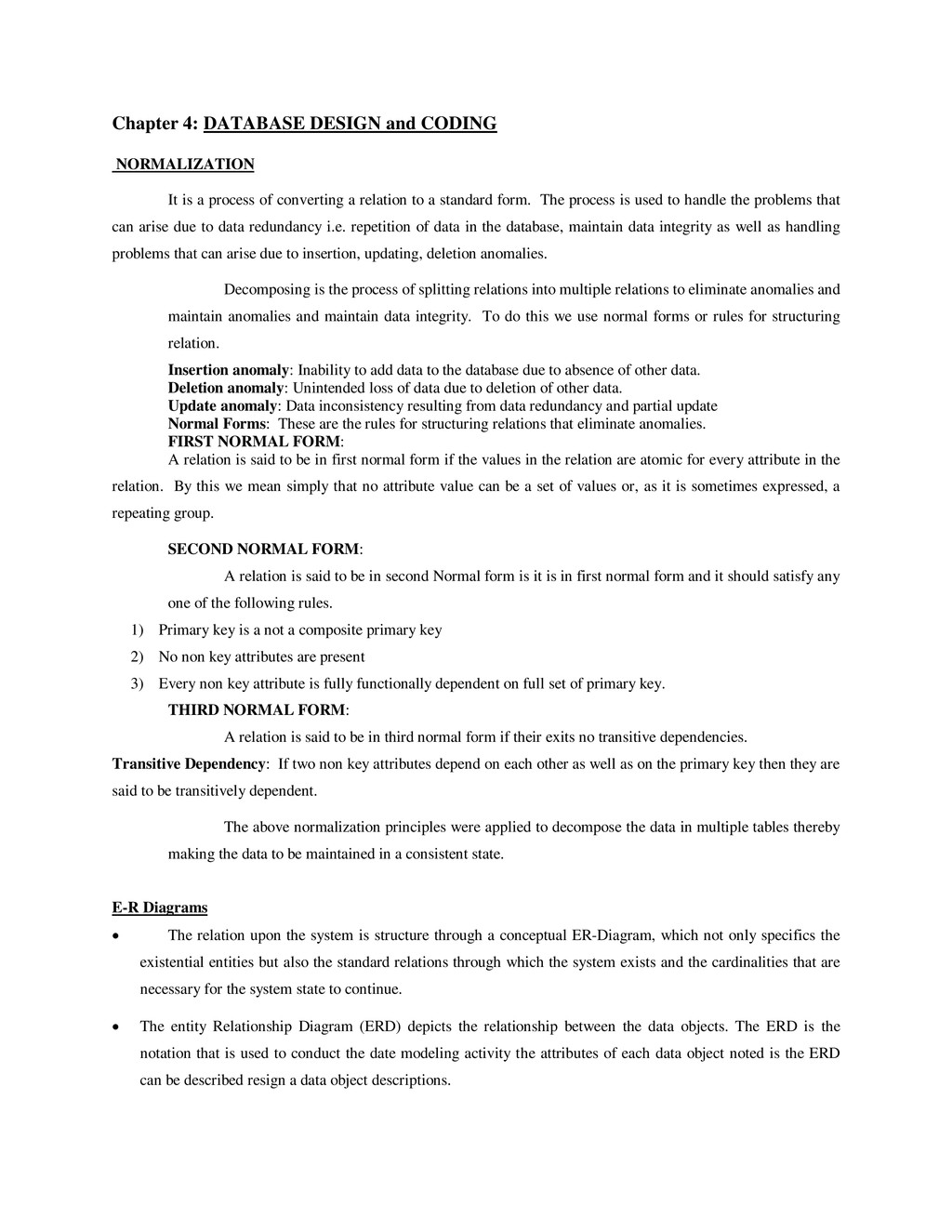
process of converting a relation to a standard form. The process is used to handle the problems that can arise due to data redundancy i.e. repetition of data in the database, maintain data integrity as well as handling problems that can arise due to insertion, updating, deletion anomalies. Decomposing is the process of splitting relations into multiple relations to eliminate anomalies and maintain anomalies and maintain data integrity. To do this we use normal forms or rules for structuring relation. Insertion anomaly: Inability to add data to the database due to absence of other data. Deletion anomaly: Unintended loss of data due to deletion of other data. Update anomaly: Data inconsistency resulting from data redundancy and partial update Normal Forms: These are the rules for structuring relations that eliminate anomalies. FIRST NORMAL FORM: A relation is said to be in first normal form if the values in the relation are atomic for every attribute in the relation. By this we mean simply that no attribute value can be a set of values or, as it is sometimes expressed, a repeating group. SECOND NORMAL FORM: A relation is said to be in second Normal form is it is in first normal form and it should satisfy any one of the following rules. 1) Primary key is a not a composite primary key 2) No non key attributes are present 3) Every non key attribute is fully functionally dependent on full set of primary key. THIRD NORMAL FORM: A relation is said to be in third normal form if their exits no transitive dependencies. Transitive Dependency: If two non key attributes depend on each other as well as on the primary key then they are said to be transitively dependent. The above normalization principles were applied to decompose the data in multiple tables thereby making the data to be maintained in a consistent state. E-R Diagrams The relation upon the system is structure through a conceptual ER-Diagram, which not only specifics the existential entities but also the standard relations through which the system exists and the cardinalities that are necessary for the system state to continue. The entity Relationship Diagram (ERD) depicts the relationship between the data objects. The ERD is the notation that is used to conduct the date modeling activity the attributes of each data object noted is the ERD can be described resign a data object descriptions.
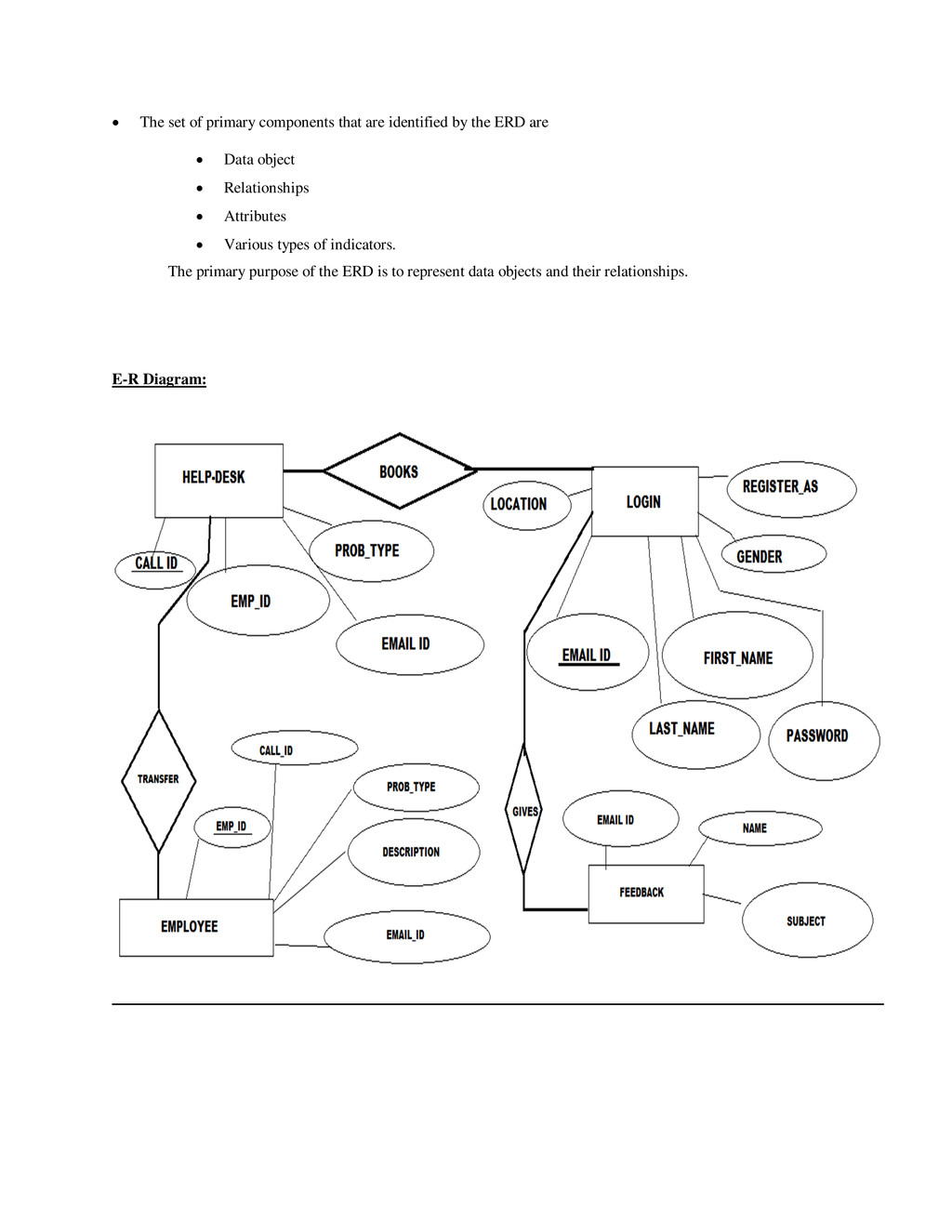
the ERD are Data object Relationships Attributes Various types of indicators. The primary purpose of the ERD is to represent data objects and their relationships. E-R Diagram:
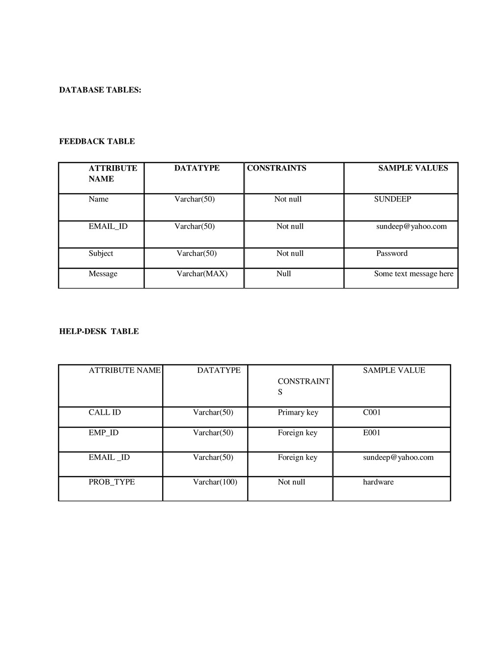
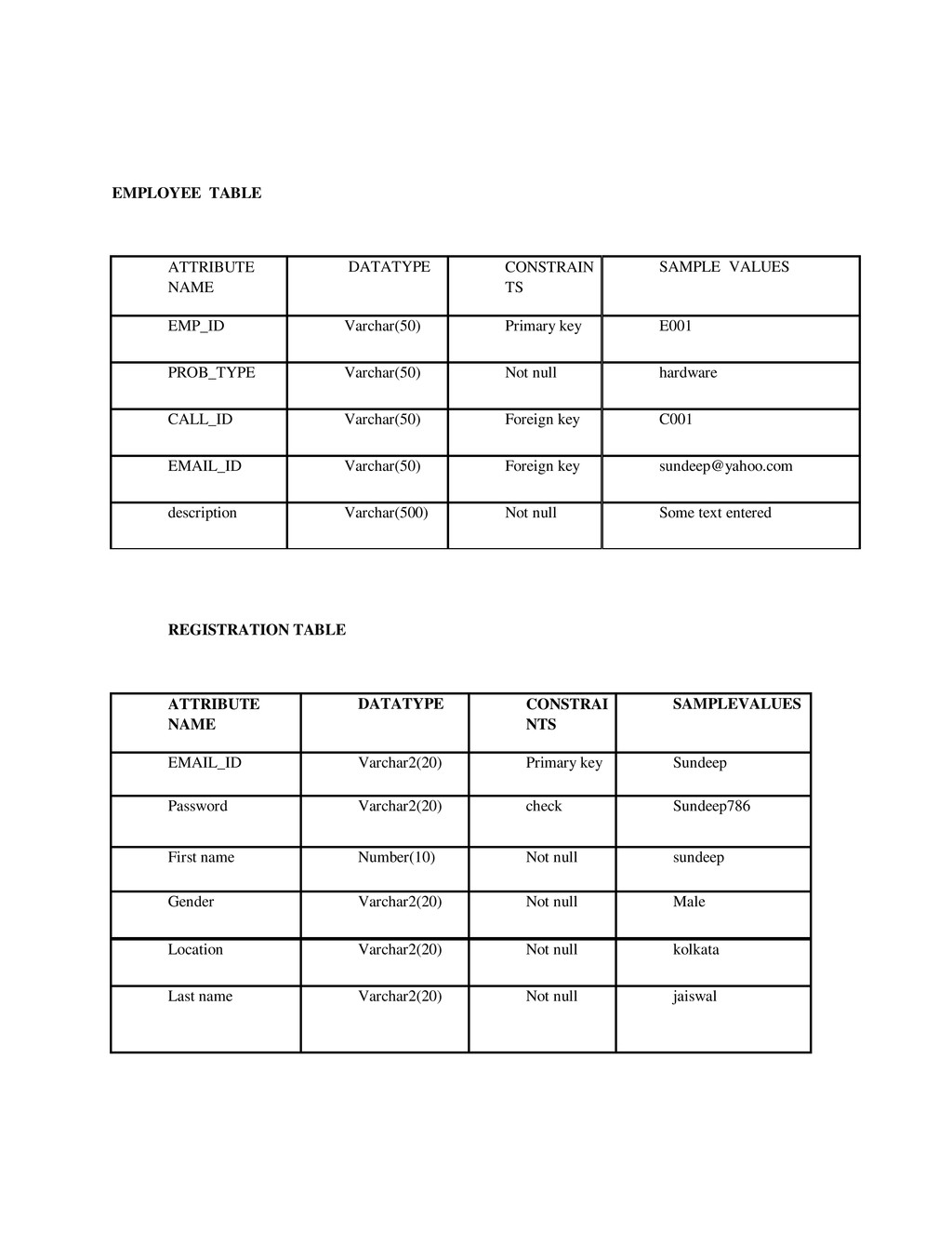
Name Varchar(50) Not null SUNDEEP EMAIL_ID Varchar(50) Not null [email protected] Subject Varchar(50) Not null Password Message Varchar(MAX) Null Some text message here HELP-DESK TABLE ATTRIBUTE NAME DATATYPE CONSTRAINT S SAMPLE VALUE CALL ID Varchar(50) Primary key C001 EMP_ID Varchar(50) Foreign key E001 EMAIL _ID Varchar(50) Foreign key [email protected] PROB_TYPE Varchar(100) Not null hardware
Varchar(50) Primary key E001 PROB_TYPE Varchar(50) Not null hardware CALL_ID Varchar(50) Foreign key C001 EMAIL_ID Varchar(50) Foreign key [email protected] description Varchar(500) Not null Some text entered REGISTRATION TABLE ATTRIBUTE NAME DATATYPE CONSTRAI NTS SAMPLEVALUES EMAIL_ID Varchar2(20) Primary key Sundeep Password Varchar2(20) check Sundeep786 First name Number(10) Not null sundeep Gender Varchar2(20) Not null Male Location Varchar2(20) Not null kolkata Last name Varchar2(20) Not null jaiswal
of software quality assurance and represents the ultimate review of specification, design and coding. In fact, testing is the one step in the software engineering process that could be viewed as destructive rather than constructive. A strategy for software testing integrates software test case design methods into a well-planned series of steps that result in the successful construction of software. Testing is the set of activities that can be planned in advance and conducted systematically. The underlying motivation of program testing is to affirm software quality with methods that can economically and effectively apply to both strategic to both large and small-scale systems. STRATEGIC APPROACH TO SOFTWARE TESTING The software engineering process can be viewed as a spiral. Initially system engineering defines the role of software and leads to software requirement analysis where the information domain, functions, behavior, performance, constraints and validation criteria for software are established. Moving inward along the spiral, we come to design and finally to coding. To develop computer software we spiral in along streamlines that decrease the level of abstraction on each turn. A strategy for software testing may also be viewed in the context of the spiral. Unit testing begins at the vertex of the spiral and concentrates on each unit of the software as implemented in source code. Testing progress by moving outward along the spiral to integration testing, where the focus is on the design and the construction of the software architecture. Talking another turn on outward on the spiral we encounter validation testing where requirements established as part of software requirements analysis are validated against the software that has been constructed. Finally we arrive at system testing, where the software and other system elements are tested as a whole.
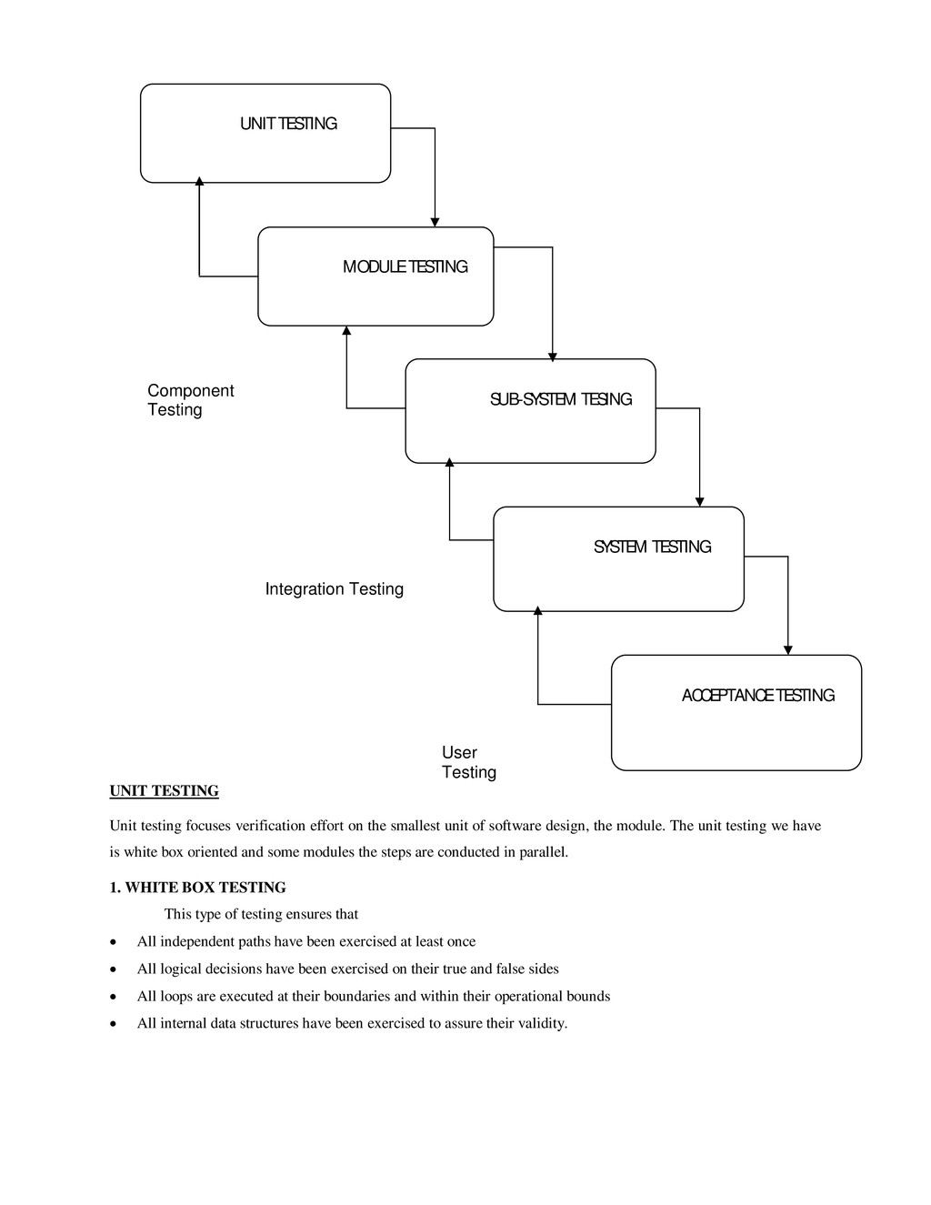
unit of software design, the module. The unit testing we have is white box oriented and some modules the steps are conducted in parallel. 1. WHITE BOX TESTING This type of testing ensures that All independent paths have been exercised at least once All logical decisions have been exercised on their true and false sides All loops are executed at their boundaries and within their operational bounds All internal data structures have been exercised to assure their validity. UNIT TESTING MODULE TESTING SUB-SYSTEM TESING SYSTEM TESTING ACCEPTANCE TESTING Component Testing Integration Testing User Testing
tested each form .we have created independently to verify that Data flow is correct, All conditions are exercised to check their validity, All loops are executed on their boundaries. 2. BASIC PATH TESTING Established technique of flow graph with Cyclomatic complexity was used to derive test cases for all the functions. The main steps in deriving test cases were: Use the design of the code and draw correspondent flow graph. Determine the Cyclomatic complexity of resultant flow graph, using formula: V(G)=E-N+2 or V(G)=P+1 or V(G)=Number Of Regions Where V(G) is Cyclomatic complexity, E is the number of edges, N is the number of flow graph nodes, P is the number of predicate nodes. Determine the basis of set of linearly independent paths. 3. CONDITIONAL TESTING In this part of the testing each of the conditions were tested to both true and false aspects. And all the resulting paths were tested. So that each path that may be generate on particular condition is traced to uncover any possible errors. 4. DATA FLOW TESTING This type of testing selects the path of the program according to the location of definition and use of variables. This kind of testing was used only when some local variable were declared. The definition-use chain method was used in this type of testing. These were particularly useful in nested statements. 5. LOOP TESTING In this type of testing all the loops are tested to all the limits possible. The following exercise was adopted for all loops: All the loops were tested at their limits, just above them and just below them. All the loops were skipped at least once. For nested loops test the inner most loop first and then work outwards. For concatenated loops the values of dependent loops were set with the help of connected loop. Unstructured loops were resolved into nested loops or concatenated loops and tested as above. Each unit has been separately tested by the development team itself and all the input have been validated. Software maintenance Modifying a program after it has been put into use. Maintenance does not normally involve major changes to the system’s architecture. Changes are implemented by modifying existing components and adding new components to the system. Types of maintenance Maintenance to repair software faults
meets its requirements. Maintenance to adapt software to a different operating environment • Changing a system so that it operates in a different environment (computer, OS, etc.) from its initial implementation. Maintenance to add to or modify the system’s functionality • Modifying the system to satisfy new requirements.
work on this exciting and challenging project. This project proved good for me as it provided practical knowledge of not only programming in ASP.NET web based application, but also about all handling procedure related with “Call management system”. It also provides knowledge about the latest technology used in developing web enabled application and client server technology that will be great demand in future. This will provide better opportunities and guidance in future in developing projects independently. BENEFITS: The project is identified by the merits of the system offered to the user. The merits of this project are as follows: - It’s a web-enabled project. This project offers user to enter the data through simple and interactive forms. This is very helpful for the client to enter the desired information through so much simplicity. The user is mainly more concerned about the validity of the data, whatever he is entering. There are checks on every stages of any new creation, data entry or updation so that the user cannot enter the invalid data, which can create problems at later date. Sometimes the user finds in the later stages of using project that he needs to update some of the information that he entered earlier. There are options for him by which he can update the records. Moreover there is restriction for his that he cannot change the primary data field. This keeps the validity of the data to longer extent. User is provided the option of monitoring the records he entered earlier. He can see the desired records with the variety of options provided by him. From every part of the project the user is provided with the links through framing so that he can go from one option of the project to other as per the requirement. This is bound to be simple and very friendly as per the user is concerned. That is, we can sat that the project is user friendly which is one of the primary concerns of any good project. Data storage and retrieval will become faster and easier to maintain because data is stored in a systematic manner and in a single database. Decision making process would be greatly enhanced because of faster processing of information since data collection from information available on computer takes much less time then manual system. Allocating of sample results becomes much faster because at a time the user can see the records of last years. Easier and faster data transfer through latest technology associated with the computer and communication. Through these features it will increase the efficiency, accuracy and transparency, LIMITATIONS: The size of the database increases day-by-day, increasing the load on the database back up and data maintenance activity. Training for simple computer operations is necessary for the users working on the system.
of Cyber Security Division, needs to be thoroughly tested to find out any security gaps. A console for the data centre may be made available to allow the personnel to monitor on the sites which were cleared for hosting during a particular period. Moreover, it is just a beginning; further the system may be utilized in various other types of auditing operation viz. Network auditing or similar process/workflow based applications…
FOR ASP.NET www.msdn.microsoft.com/net/quickstart/aspplus/default.com www.asp.net www.fmexpense.com/quickstart/aspplus/default.com Software Engineering (Roger’s Pressman) Asp.net Ebook (WROX Publication)