Upgrade to Pro — share decks privately, control downloads, hide ads and more …

Caterpillar_Cat_980K_Wheel_Loader__Prefix_W7K__...

dcfv
May 20, 2024
4

 Caterpillar_Cat_980K_Wheel_Loader__Prefix_W7K__Service_Repair_Manual__W7K00001_and_up_.pdf

dcfv

May 20, 2024
Tweet

More Decks by dcfv

Transcript

  1. Shutdown SIS Previous Screen Product: WHEEL LOADER Model: 980K WHEEL

    LOADER W7K Configuration: 980K Wheel Loader W7K00001-UP (MACHINE) POWERED BY C13 Engine Disassembly and Assembly 980K Wheel Loader Power Train Media Number -KENR6447-03 Publication Date -01/08/2012 Date Updated -21/08/2012 i06838048 Torque Converter - Disassemble - Lock Up Clutch With Freewheel Stator SMCS - 3101-015 Disassembly Procedure Table 1 Required Tools Tool Part Number Part Description Qty A 439-3938 Link Bracket 3 B 8B-7548 Push-Puller 1 8B-7550 Leg 2 8H-0684 Ratchet Wrench 1 8B-7560 Step Plate 1 8H-0663 Bearing Puller Attachment 1 C 8B-7548 Push-Puller 1 8H-0684 Ratchet Wrench 1 8B-7549 Leg 2 5P-4808 Cap 2 8B-7554 Bearing Cup Puller Attachment 1 D 5F-7343 Bearing Puller Attachment 1 1P-0520 Driver Group 1 E 1P-0510 Driver Group 1
  2. F 6L-7283 Forcing Bolt 3/8 - 16 by 3 in

    7 G 417-1324 Adjust Stand 1 Start By: a. Separate the torque converter from the transmission and from the output transfer gears. Illustration 1 g02712129 1. Use Tooling (A) and a suitable lifting device to position the torque converter onto Tooling (G) and suitable blocking. The weight of the torque converter is approximately 260 kg (573 lb). Support the torque converter, as shown. 2. Remove bolts (1). Illustration 2 g02730506 3. Remove relief valve assembly (2A).
  3. Illustration 3 g02711758 4. Use Tooling (F) to loosen housing

    assembly (2) from the torque converter. 5. Use the suitable lifting device and Tooling (A) to remove torque converter housing assembly (2). The weight of torque converter housing assembly (2) is approximately 144 kg (317 lb). Illustration 4 g00871317 6. Remove O-ring seal (3) from torque converter housing assembly (2). Illustration 5 g00871318
  4. 7. Remove bolts (4) from pump adapter (5) and torque

    converter housing assembly (2). Illustration 6 g00871264 8. Use Tooling (F) to remove pump adapter (5) from torque converter housing assembly (2). Illustration 7 g00871319 9. Use Tooling (B) to remove bearing cup (6). Remove bearing cup (6), O-ring seal (8), and shims (7) from pump adapter (5). See illustration 14 for Tooling (C). Illustration 8 g00871326 10. Remove pump drive gear (9) from torque converter housing assembly (2).
  5. https://www.aservicemanualpdf.com/ My Dear Friend! Thank you very much for visiting.

    Full manual if required, please enter the following URL into your browser. https://www.aservicemanualpdf.com/
  6. Illustration 9 g00871451 11. Use Tooling (C) to remove bearing

    cones (10) from each side of pump drive gear (9). Remove bearing cones (10). Illustration 10 g00871333 12. Use Tooling (C) to remove bearing cup (11) from torque converter housing assembly (2). See illustration 14 for Tooling (C). Illustration 11 g01112900 13. Remove bolt (12) and the washer from torque converter housing assembly (2).
  7. 14. Use Tooling (F) to push shaft assembly (14) out

    of torque converter housing assembly (2). 15. Remove idler gear (13) from torque converter housing assembly (2). Illustration 12 g01112903 16. Remove O-ring seal (15) from shaft assembly (14). Illustration 13 g00871365 17. Remove bearing cone (16), bearing cone spacer (17), and bearing cone (18) from idler gear (13).
  8. Illustration 14 g00871366 18. Use Tooling (C) to remove bearing

    cup (19) from idler gear (13). Remove bearing cup (19). Illustration 15 g00871367 19. Remove bearing cup spacer (20) from idler gear (13). Illustration 16 g00871368
  9. 20. Remove retaining ring (21) from idler gear (13). Illustration

    17 g00871369 21. Use Tooling (C) to remove bearing cup (22) from idler gear (13). Remove bearing cup (22). Illustration 18 g00871370 22. Remove studs (23) from torque converter housing assembly (2).
  10. Illustration 19 g02729366 23. Remove bolts (24) and gear (25).

    Illustration 20 g02735357 24. Use the driver group from Tooling (D) and a suitable press to remove race (25A) from gear (25). Illustration 21 g02730012 25. Use a suitable lifting device to reposition the torque converter, as shown. The weight of the torque converter is approximately 122 kg (269 lb). Remove bolts (26).
  11. Illustration 22 g02730687 26. Use Tooling (F) to separate housing

    (27) from the torque converter. Illustration 23 g02730689 27. Use two people to remove housing (27). The weight of housing (27) is approximately 26 kg (57 lb). Remove housing (27), piston (28), and plate (30). Remove seals (29) from piston (28). Illustration 24 g02731059 28. Remove bushing (31) from housing (27).
  12. Illustration 25 g02731623 29. Remove plate (32), disk (33), races

    (34), and bearing (35). Note: Note the orientation of the bearing and races for assembly purposes. Illustration 26 g02731644 30. Remove bolts (36), coupling assembly (37), and plate (38).
  13. Illustration 27 g02731651 31. Use suitable blocking to support the

    bottom of shaft assembly (39). Remove retaining ring (40) and plate (41). Shaft assembly (39) can be lowered to the work bench. Illustration 28 g02731711 Illustration 29 g02732048
  14. 32. Install two of bolts (36) and remove turbine (42).

    33. Remove bolts (36) and remove hub (43) from turbine (42). Illustration 30 g02731732 Illustration 31 g02731802 34. Remove race (44) and bearing (45). Note: Note the orientation of the race and bearing for assembly purposes. 35. Remove stator assembly (46).
  15. Illustration 32 g02731806 36. Remove retaining ring (47), plate (48),

    freewheel springs (49), freewheel rollers (50), and freewheel cam (51). Remove plate (52) and retaining ring (53) (not shown) from stator (46). Illustration 33 g02732255 37. Attach Tooling (A) and a suitable lifting device to impeller (54). The weightof impeller (54) is approximately 27 kg (60 lb). 38. Remove impeller (54) from shaft assembly (39). Illustration 34 g02735333 39. Position impeller (54) onto suitable blocking, as shown.
  16. Illustration 35 g02734776 40. Remove retaining ring (56) and hub

    (55). Illustration 36 g02735372 41. Remove seal ring (56). Illustration 37 g02734816 42. Use Tooling (D) and a suitable press to remove bearing (57). Illustration 38 g02735374
  17. 43. Remove retaining ring (59) and carrier assembly (58) from

    impeller (54). Illustration 39 g02735380 44. Remove bearing (60). Note: Note the orientation of the bearing (60) for assembly purposes. Illustration 40 g02735387 45. Remove bolts (61), hub (62), and adapter (63) from impeller (54).
  18. Illustration 41 g02752296 46. Remove seals (64). Copyright 1993 -

    2022 Caterpillar Inc. All Rights Reserved. Private Network For SIS Licensees. Sun Feb 13 14:22:42 UTC+0800 2022
  19. Shutdown SIS Previous Screen Product: WHEEL LOADER Model: 980K WHEEL

    LOADER W7K Configuration: 980K Wheel Loader W7K00001-UP (MACHINE) POWERED BY C13 Engine Disassembly and Assembly 980K Wheel Loader Power Train Media Number -KENR6447-03 Publication Date -01/08/2012 Date Updated -21/08/2012 i06806533 Torque Converter - Assemble - Lock Up Clutch with Freewheel Stator SMCS - 3101-016 Assembly Procedure Table 1 Required Tools Tool Part Number Part Description Qty A 138-7573 Link Bracket 3 G 8T-5096 Dial Indicator Test Group 1 5P-2390 Gauge Tool Group 1 H 1P-0520 Driver Group 1 J - Guide Stud (3/8 - 16 by 8 in) 2 K - Guide Stud (1/2 - 13 by 3 in) 3 L 2P-8312 Retaining Ring Pliers 1 Note: Cleanliness is an important factor. Before assembly, all parts should be thoroughly cleaned in cleaning fluid. Allow the parts to air dry. Wiping cloths or rags should not be used to dry parts. Lint may be deposited on the parts which may cause later trouble. Inspect all parts. If any parts are worn or damaged, use new parts for replacement. Note: Apply oil to all of the bearings before assembly.
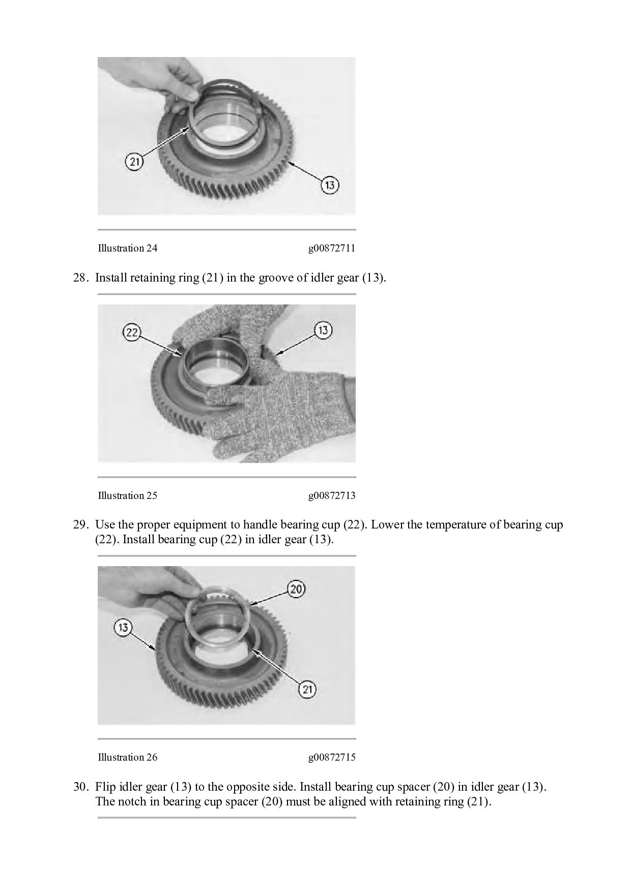
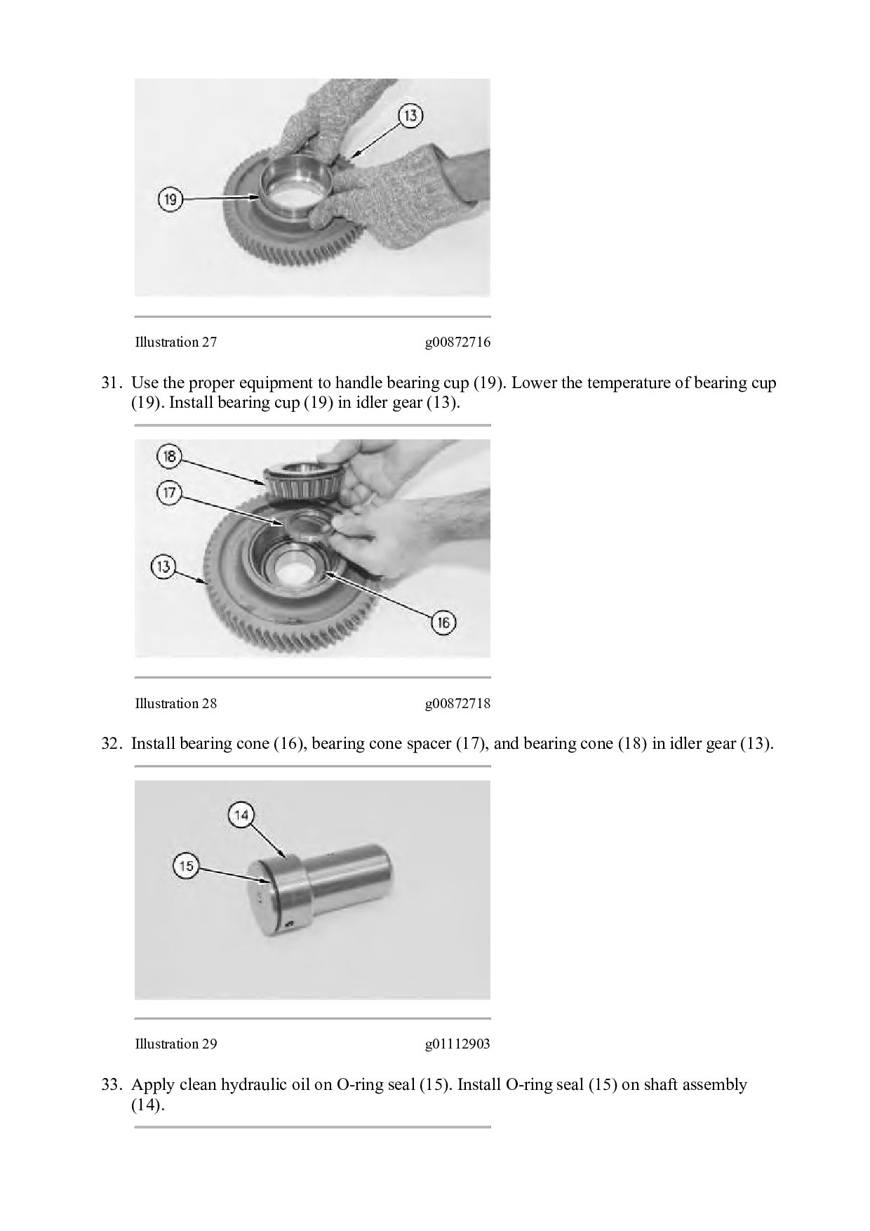
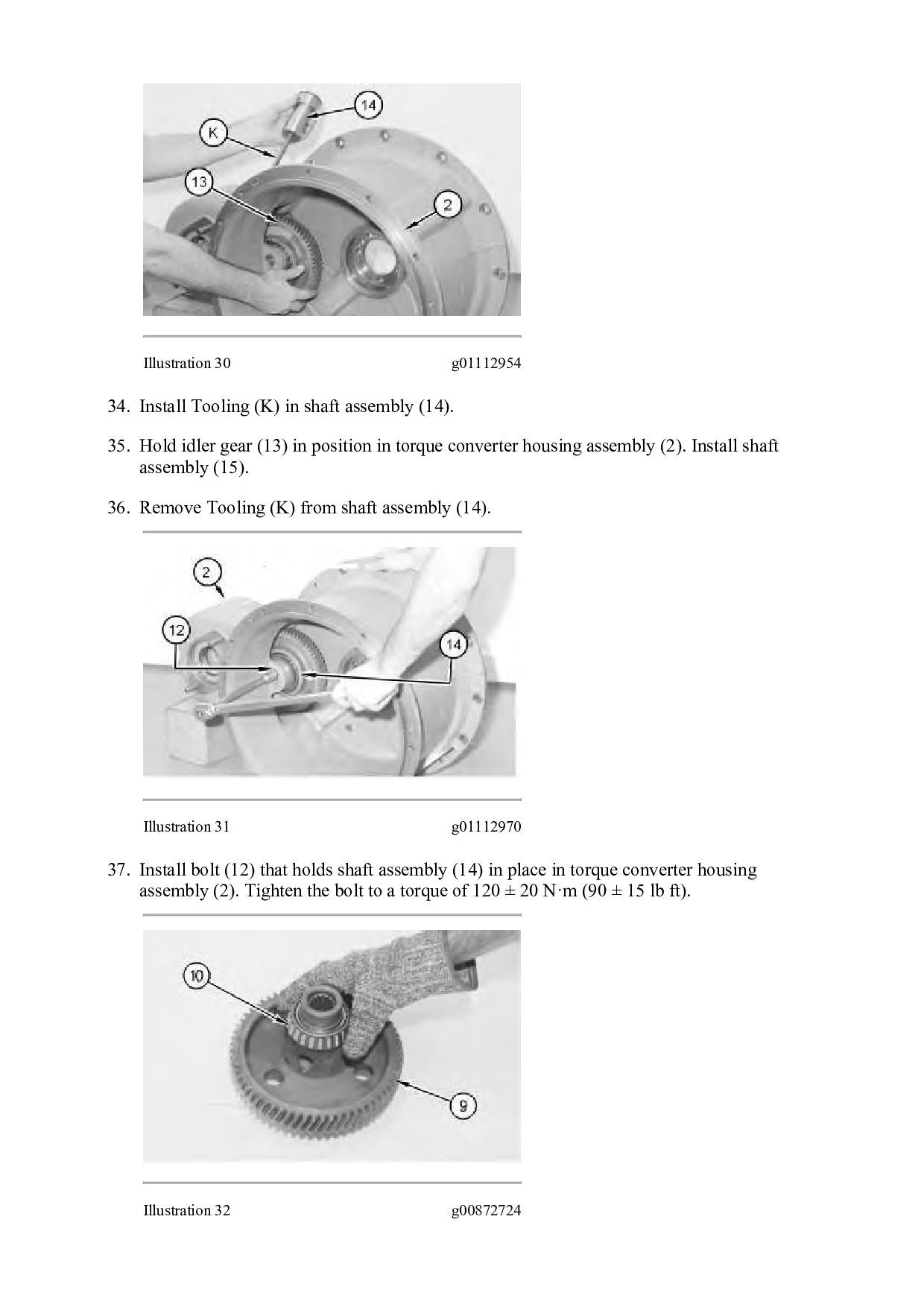
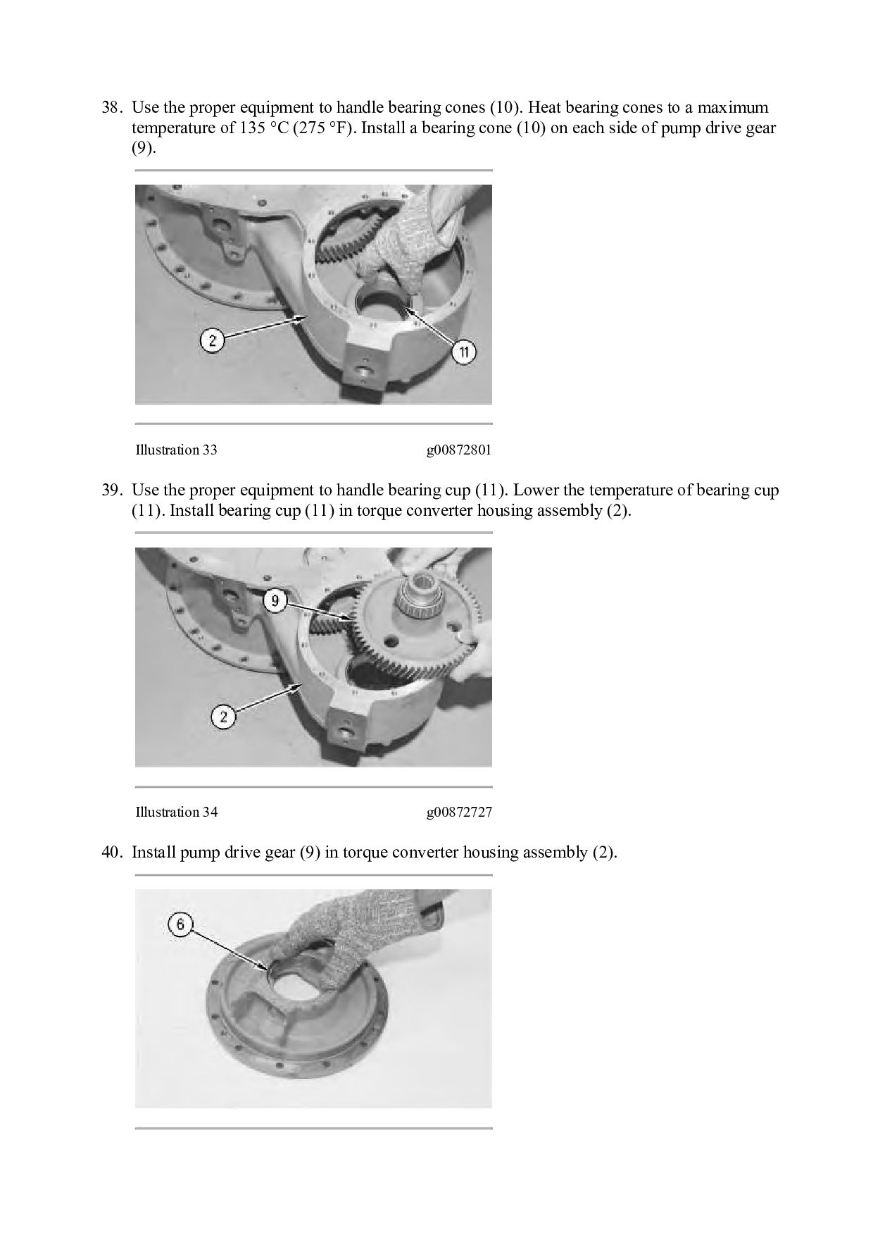
  20. Illustration 1 g02735387 1. Install adapter (63), hub (62), and

    bolts (61) onto impeller (54). Tighten bolts (61) to a torque or 105 ± 14 N·m (77 ± 10 lb ft). Illustration 2 g02735380 2. Install bearing (60). Illustration 3 g02735374 3. Install carrier assembly (58) and retaining ring (59) onto impeller (54).
  21. Illustration 4 g06122365 4. Raise the temperature of bearing (57).

    Install bearing (57) onto hub (55). 5. Install retaining ring (56A) and seal ring (56). Illustration 5 g02734776 Illustration 6 g02735333 6. Install hub (55) and retaining ring (56) onto impeller (54).
  22. Illustration 7 g02752296 7. Install seals (64). Illustration 8 g02732255

    8. Attach Tooling (A) and a suitable lifting device to impeller (54). The weightof impeller (54) is approximately 27 kg (60 lb). 9. Position impeller (54) onto shaft assembly (39). Illustration 9 g02731806
  23. Illustration 10 g06122374 Typical Example 10. Install retaining ring (53)

    (not shown) and plate (52) onto stator (46). 11. Install freewheel cam (51), freewheel rollers (50), and springs (49). Note: Springs (49) must be installed with the maximum number or loops to the outside. 12. Install plate (48) and retaining ring (47). Illustration 11 g02731802 Illustration 12 g06122399
  24. 13. Install stator assembly (46). 14. Install bearing (45) race

    (44), and outer race (44A). Illustration 13 g02744699 Illustration 14 g06122404 15. Install hub (43) and turbine (42). 16. Use two of bolts (36) to align the holes. 17. Use suitable blocking to support the bottom of shaft assembly (39). Install plate (41),retaining ring (40), and ring seal (39A).
  25. Illustration 15 g06122416 18. Install springs (36A) and (36B) inside

    of springs (36). Install springs (36) in an alternating pattern. An example would be to install a spring (36) with a spring (36A) inside. The next one would be to install a spring (36) with a spring (36B) inside. Illustration 16 g06122422 19. Install plate (38), coupling assembly (37), and bolts (36). Tighten bolts (36) to a torque of 60 ± 7 N·m (44 ± 5 lb ft). Note: Plate (38) has an O-ring groove that is not used.
  26. Illustration 17 g06122434 20. Install disk (33), races (34), and

    bearing (35). Illustration 18 g02731059 21. Lower the temperature of bushing (31). Install bushing (31) into housing (27).
  27. Illustration 19 g02730689 22. Install seals (29) onto piston (28).

    Install plate (30), piston (28), and housing (27). Note: Plate (30) has an O-ring groove that is not used. Illustration 20 g02730012 23. Tighten bolts (26). Tighten bolts (36) to a torque of 60 ± 7 N·m (44 ± 5 lb ft).
  28. Illustration 21 g02735357 24. Lower the temperature of race (25A).

    If necessary, use the driver group from Tooling (D) and a suitable press to install race (25A) into gear (25). Illustration 22 g02729366 25. Use a suitable lifting devise to reposition the torque converter, as shown. The weight of the torque converter is approximately 1157 N (260 lb). 26. Install drive gear (25) and bolts (24). Tighten the bolts to a torque of 50 ± 7 N·m (37 ± 5 lb ft). Illustration 23 g00872709 27. Install studs (23) in torque converter housing assembly (2). Tighten the studs to a torque of 100 ± 15 N·m (74 ± 11 lb ft).
  29. Illustration 24 g00872711 28. Install retaining ring (21) in the

    groove of idler gear (13). Illustration 25 g00872713 29. Use the proper equipment to handle bearing cup (22). Lower the temperature of bearing cup (22). Install bearing cup (22) in idler gear (13). Illustration 26 g00872715 30. Flip idler gear (13) to the opposite side. Install bearing cup spacer (20) in idler gear (13). The notch in bearing cup spacer (20) must be aligned with retaining ring (21).
  30. Illustration 27 g00872716 31. Use the proper equipment to handle

    bearing cup (19). Lower the temperature of bearing cup (19). Install bearing cup (19) in idler gear (13). Illustration 28 g00872718 32. Install bearing cone (16), bearing cone spacer (17), and bearing cone (18) in idler gear (13). Illustration 29 g01112903 33. Apply clean hydraulic oil on O-ring seal (15). Install O-ring seal (15) on shaft assembly (14).
  31. Illustration 30 g01112954 34. Install Tooling (K) in shaft assembly

    (14). 35. Hold idler gear (13) in position in torque converter housing assembly (2). Install shaft assembly (15). 36. Remove Tooling (K) from shaft assembly (14). Illustration 31 g01112970 37. Install bolt (12) that holds shaft assembly (14) in place in torque converter housing assembly (2). Tighten the bolt to a torque of 120 ± 20 N·m (90 ± 15 lb ft). Illustration 32 g00872724
  32. 38. Use the proper equipment to handle bearing cones (10).

    Heat bearing cones to a maximum temperature of 135 °C (275 °F). Install a bearing cone (10) on each side of pump drive gear (9). Illustration 33 g00872801 39. Use the proper equipment to handle bearing cup (11). Lower the temperature of bearing cup (11). Install bearing cup (11) in torque converter housing assembly (2). Illustration 34 g00872727 40. Install pump drive gear (9) in torque converter housing assembly (2).
  33. Thank you very much for your reading. Please Click Here.

    Then Get COMPLETE MANUAL. NO WAITING NOTE: If there is no response to click on the link above, please download the PDF document first and then click on it.
  34. Illustration 35 g00872729 41. Use the proper equipment to handle

    bearing cup (6). Lower the temperature of bearing cup (6). Illustration 36 g00871319 42. Apply clean hydraulic oil on O-ring seal (8). 43. Install bearing cup (6), O-ring seal (8), and shims (7) on pump adapter (5). Illustration 37 g01112978 44. Install Tooling (J) in torque converter housing assembly (2). 45. Install pump adapter (5) on torque converter housing assembly (2).
  35. Illustration 38 g01112982 46. Install bolts (4) and the washers

    on pump adapter (5) and torque converter housing assembly (2). 47. Use Tooling (G) to check bearing end play. The bearing end play must be 0.15 ± 0.05 mm (0.006 ± 0.002 inch). Add or remove shims to get the correct bearing end play. Note: If end play is less than 0.10 mm (0.004 inch) add additional shims. If end play is greater than 0.20 mm (0.008 inch) remove shims. Illustration 39 g00872732 48. If equipped apply clean hydraulic oil on O-ring seal (3). Install O-ring seal (3) on torque converter housing assembly (2).
  36. Illustration 40 g02730506 49. Install relief valve assembly (2A). Illustration

    41 g02752336 Illustration 42 g02752337 50. Install Tooling (J) in the carrier assembly. 51. Use Tooling (A) and a suitable lifting devise to position torque converter housing assembly (2) to position torque converter housing assembly (2) on the torque converter, as shown. The weight of torque converter housing assembly is approximately 144 kg (317 lb). Install the bearing flange (not shown), plate (not shown), and two of bolts (1).
  37. https://www.aservicemanualpdf.com/ My Dear Friend! Thank you very much for visiting.

    Full manual if required, please enter the following URL into your browser. https://www.aservicemanualpdf.com/