Upgrade to Pro — share decks privately, control downloads, hide ads and more …

Caterpillar_Cat_D6M_TRACK-TYPE_TRACTOR__Prefix_4GS__Service_Repair_Manual__4GS00001_and_up_.pdf

dcfv
May 21, 2024
4

 Caterpillar_Cat_D6M_TRACK-TYPE_TRACTOR__Prefix_4GS__Service_Repair_Manual__4GS00001_and_up_.pdf

dcfv

May 21, 2024
Tweet

More Decks by dcfv

Transcript

  1. Shutdown SIS Previous Screen Product: TRACK-TYPE TRACTOR Model: D6M TRACK-TYPE

    TRACTOR 4GS Configuration: D6M XL & D6M LGP TRACTORS / POWERSHIFT / 4GS00001-UP (MACHINE) POWERED BY 3116 ENGINE Disassembly and Assembly D6M Track-Type Tractor Power Train Media Number -SENR9482-04 Publication Date -01/01/2011 Date Updated -31/01/2011 i00964522 Bevel and Transfer Gears - Assemble Assembly Procedure Table 1 Tools Needed A B C D E 8T-2839 Spanner Wrench 1 FT-1986 Stud 1 1 2P-8257 Plate 1 1 6B-6684 Nut 5 9 2P-8260 Cylinder Liner Installer 1 1 4B-5273 Washer 3 4 1D-4719 Nut 2 2 0S-1590 Bolt3/8 inch - 16 NC x 2 inch (50.8 mm) 1 1 8S-2328 Dial Indicator Group 1 1P-520 Driver Group 1 1P-1833 Adapter 1 1P-1839 Adapter 1
  2. Illustration 1 g00709050 1. If bearing race (43) was removed,

    lower the temperature of the bearing race. Install the bearing race in the case assembly. Illustration 2 g00709055 2. Install bearing cones (42) and bearing cups (41) in cage (39) . Illustration 3 g00709060
  3. 3. Install the original amount of shims (40) and cage

    in the case assembly. Illustration 4 g00709062 4. Put retainer (38) in position. Install bolts (37) . Illustration 5 g00709063 5. If bearing (36) was removed, heat the bearing to a maximum temperature of 135°C (275°F). Install the bearing on shaft (33) .
  4. Illustration 6 g00709064 6. Put gear (35) in position on

    shaft (33). Install bolts (34) . Illustration 7 g00709067 7. Fasten a hoist to shaft (33). Put the shaft in position in the case assembly. Remove the hoist from the shaft. Install the shaft all the way. Illustration 8 g00709310
  5. https://www.aservicemanualpdf.com/ My Dear Friend! Thank you very much for visiting.

    Full manual if required, please enter the following URL into your browser. https://www.aservicemanualpdf.com/
  6. 8. Put the washer and washer (31) in position on

    the shaft. 9. Put 5P-3931 Anti-Seize Compound on the threads and face of nut (32). Install the nut on the shaft. Use Tool (B) in order to tighten the nut to a torque of 612 N·m ± 68 N·m (450 lb ft ± 50 lb ft). Illustration 9 g00709317 10. If bearing cups (29) and (30) were removed, lower the temperature of bearing cups. Install the bearing cups in the case assembly. The bearing cups must be seated in the case assembly. Illustration 10 g00709318 Note: If the bearing cones were removed from gear (22), new bearing cones must be installed. 11. Heat bearing cones (27) and (28) to a maximum temperature of 135°C (275°F). Install the bearing cones on gear (22). The bearing cones must be seated on the gear.
  7. Illustration 11 g00709320 12. Put pinion (25) in position in

    gear (23) . 13. Heat bearing cones (26) to a maximum temperature of 135°C (275°F). Install the bearing cone on pinion (25). The bearing cone must be seated on the pinion. Illustration 12 g00709323 14. Heat bearing cones (24) to a maximum temperature of 135°C (275°F). Install the bearing cone on pinion (25). The bearing cone must be seated on the pinion.
  8. Illustration 13 g00709325 15. Install gear (22) and gear (23)

    in the case assembly. Illustration 14 g00709329 Illustration 15 g00709333 16. If dowels (20) were removed, install the dowel in cover (18) . 17. Install the bearing cup until dimension (X) is 4.37 mm (0.172 inch).
  9. Illustration 16 g00709337 18. Put cover (18) in position. Install

    bolts (17) . 19. Put shims (15) with a total thickness of 4.37 mm (0.172 inch) and cover (16) in position on cover (18). Install the bolts that hold the parts in place. Illustration 17 g00709339 20. Install Tooling (C), as shown. 21. Install Tooling (D) with the point of the dial indicator against the inside race of the bearing cone. 22. Use Tool (C) in order to hold the gear and the pinion down. Use a ratchet wrench in order to rotate the gear and the pinion at least three revolutions. Watch the dial indicator as the needle moves. Stop rotating the gear and the pinion at the point of maximum needle movement. 23. Zero the dial indicator. Put a mark on the bearing race at the location of maximum needle movement. 24. Use Tool (C) in order to pull the gear and the pinion upward. Rotate the gear and the pinion at least three revolutions. Stop the gear and the pinion at the same point of maximum needle movement. Record the measurement on the dial indicator. This reading is the actual bearing clearance.
  10. 25. Repeat Steps 22 through 24. The reading should be

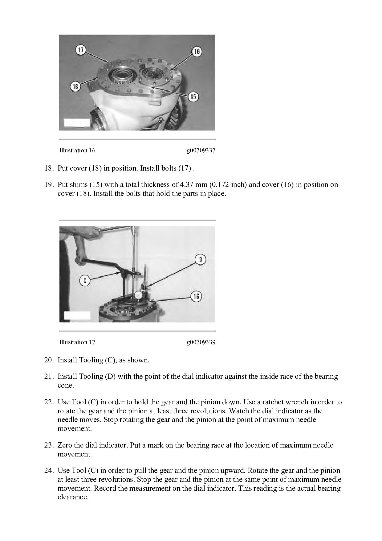
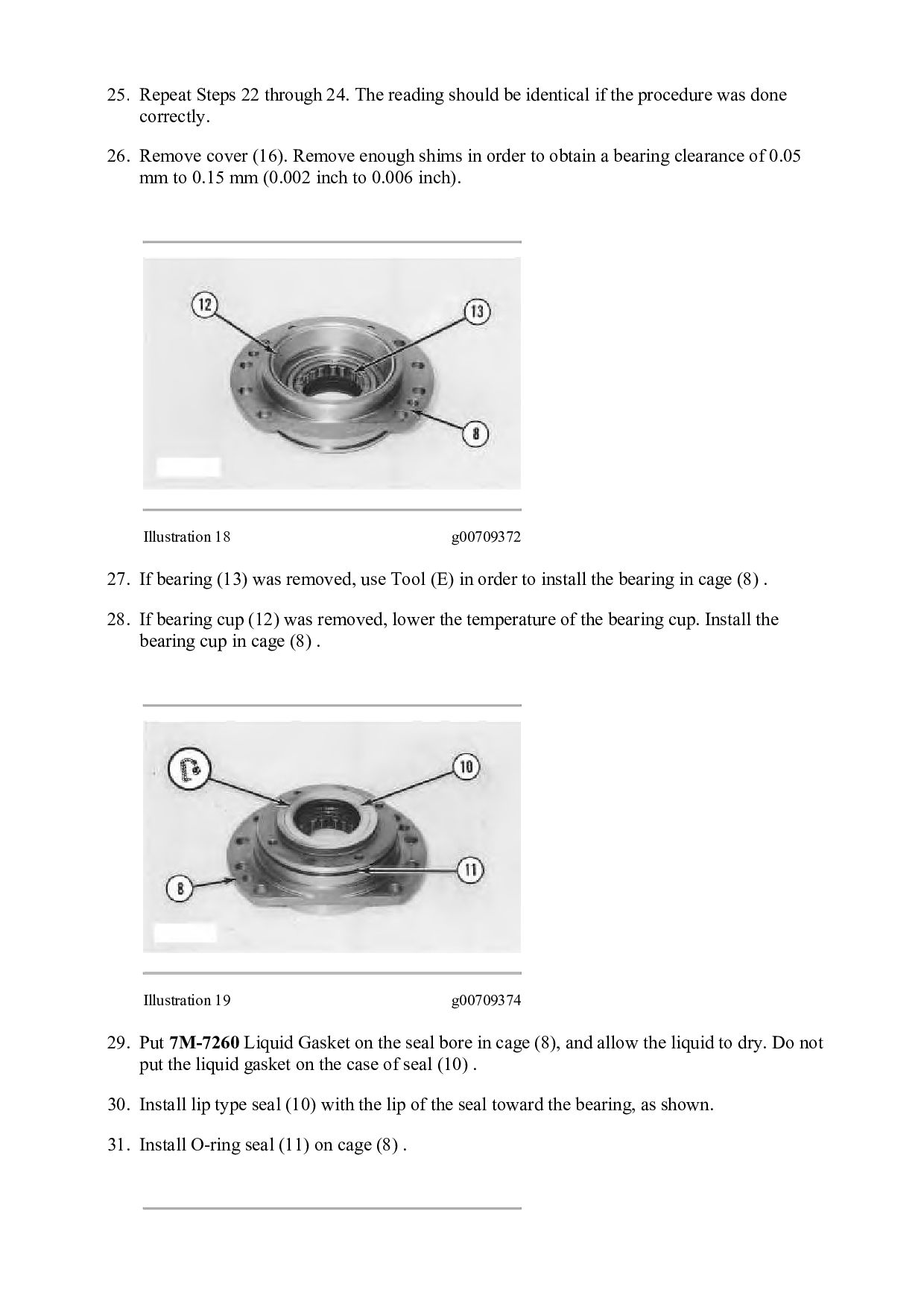
    identical if the procedure was done correctly. 26. Remove cover (16). Remove enough shims in order to obtain a bearing clearance of 0.05 mm to 0.15 mm (0.002 inch to 0.006 inch). Illustration 18 g00709372 27. If bearing (13) was removed, use Tool (E) in order to install the bearing in cage (8) . 28. If bearing cup (12) was removed, lower the temperature of the bearing cup. Install the bearing cup in cage (8) . Illustration 19 g00709374 29. Put 7M-7260 Liquid Gasket on the seal bore in cage (8), and allow the liquid to dry. Do not put the liquid gasket on the case of seal (10) . 30. Install lip type seal (10) with the lip of the seal toward the bearing, as shown. 31. Install O-ring seal (11) on cage (8) .
  11. Illustration 20 g00709377 32. Put retainer (19) in position. Install

    the bolt that holds the retainer in place. 33. Put cage (8) in position without the shims. Install two bolts (7) that are 180 degrees away from each other. 34. Tighten bolts (7) to a torque of 2.3 N·m (20.00 lb in). 35. Rotate the gear at least five revolutions. Tighten the bolts to a torque of 4.5 N·m (40.00 lb in). 36. Rotate the gear at least five revolutions again. Tighten the bolts to a torque of 4.5 N·m (40.00 lb in). 37. Use a feeler gauge in order to measure the gap between cage (8) and the cover. Take the measurements at the location of bolts (7). Average the two measurements. Illustration 21 g00709379 38. Remove bolts (7) and cage (8) from the cover. 39. Install shims (9) that are equal to the measurement in step 37 plus 0.18 mm (0.007 inch). 40. Put cage (8) in position on the shims. Install bolts (7). tighten the bolts to a torque of 135 N·m ± 15 N·m (100 lb ft ± 11 lb ft).
  12. Illustration 22 g00709381 41. Do the following procedure with Tooling

    (D) and (F) in order to check the end play of the gear. a. Push down the gear. Use Tooling (F) in order to hold the gear down. Use a ratchet wrench in order to rotate the gear at least five revolutions. Watch the dial indicator. Stop rotating the gear at the point of maximum needle movement. b. Zero the dial indicator. Put a mark at the location of maximum needle movement. c. Use Tool (F) in order to pull the gear upward. Rotate the gear at least five revolutions. Stop the gear at the same point of maximum needle movement. Record the measurement. This measurement is the actual end play of the gear. 42. Repeat Steps 41.a through 41.c. The measurement should be identical if the procedure was done correctly. The end play of the gear must be 0.05 mm to 0.15 mm (0.002 inch to 0.006 inch). Illustration 23 g00709397 43. Use mild steel to fabricate plate (44). The dimensions of plate (44) are 6.35 mm (0.25 inch) by 38.10 mm (1.5 inch) by 127 mm (5 inch).
  13. Illustration 24 g00709398 44. Install plate (44) in order to

    hold the gear and the pinion when the backlash is being checked, as shown. 45. Put Tooling (D) in position with the point of the dial indicator against gear (35) . 46. Use Tooling (D) in order to measure the backlash of gear (35). Make the measurements at three locations that are spaced evenly away from each other. The difference in the three measurements should not be more than 0.08 mm (0.003 inch). Illustration 25 g00709401 47. Add or subtract shims (40) in order to obtain a backlash of 0.10 mm to 0.30 mm (0.004 inch to 0.012 inch). Remove plate (44) after the backlash has been adjusted.
  14. Illustration 26 g00709402 48. Install O-ring seal (6) on carrier

    (5) . 49. Put carrier (5) in position. Install bolts (4) . Illustration 27 g00709403 50. Install yoke (2) . 51. Install bracket assemblies (1) and (3) . End By: Connect the transmission and bevel gears. Copyright 1993 - 2022 Caterpillar Inc. All Rights Reserved. Private Network For SIS Licensees. Mon Feb 14 11:07:35 UTC+0800 2022
  15. Shutdown SIS Previous Screen Product: TRACK-TYPE TRACTOR Model: D6M TRACK-TYPE

    TRACTOR 4GS Configuration: D6M XL & D6M LGP TRACTORS / POWERSHIFT / 4GS00001-UP (MACHINE) POWERED BY 3116 ENGINE Disassembly and Assembly D6M Track-Type Tractor Power Train Media Number -SENR9482-04 Publication Date -01/01/2011 Date Updated -31/01/2011 i04520390 Transmission - Disassemble Disassembly Procedure Table 1 Required Tools Tool Part Number Part Description Qty A 1P-2420 Transmission Repair Stand 1 B 138-7573 Link Bracket 2 D 5P-4758 Retaining Ring Pliers As 1 E 8B-7548 Push-Puller Tool Gp 1 6H-1627 Spacer 1 F 1P-1863 Retaining Ring Pliers 1 G 1P-1859 Retaining Ring Pliers 1 L 8H-0663 Bearing Puller Gp 1 Start By: A. Separate the transmission and bevel gears. Refer to Disassembly and Assembly, "Transmission and Bevel Gears-Separate". B. Remove the transmission hydraulic control valves. Refer to Disassembly and Assembly, "Transmission Hydraulic Control Valve-Remove". 1. Place the transmission on Tooling (A) .
  16. Illustration 1 g00716857 2. Install Tooling (B) in housing (1)

    . Fasten a suitable lifting device to Tooling (B) . 3. Support the weight of housing (1) with a suitable lifting device. Use Tooling (A) in order to remove snap ring (2) . 4. Remove bolts (4) and manifold (3) from the planetary group. Illustration 2 g00716853 5. Remove ring (5) and bearing (6) from housing (3) .
  17. Illustration 3 g00716852 6. Remove plates (9) and discs (8)

    . Remove springs (7) . Illustration 4 g00716848 7. Remove piston (10) from the housing assembly. Illustration 5 g00716844 8. Remove ring (108) and (109) from piston (10) .
  18. Illustration 6 g01052455 9. Install Tooling (B) in housing (1)

    . Fasten a suitable lifting device to Tooling (B) . 10. Use Tooling (D) in order to compress ring (12) . Remove housing (1) . Illustration 7 g00716837 11. Remove rings (14) and (15) from the carrier. 12. Remove ring (12) from housing (1) .
  19. Illustration 8 g00716823 13. Use Tooling (E) and a press

    in order to compress the springs in housing (1) . Remove spiral lock ring (16) from coupling (17) . Slowly release the spring tension with the press. Illustration 9 g00716821 14. Remove springs (19) and plate (20) . Remove piston (18) and coupling (17) from housing (1) . 15. Remove rings (21) and (22) from piston (18) .
  20. Illustration 10 g00716797 16. 17. Remove pin (23) and pin

    (25) from carrier (24) . 18. If necessary, break carrier (24) , and remove carrier (24) from housing assembly (1) . Note: On later transmissions, carrier (24) and housing assembly (1) are one piece. Illustration 11 g00716790 19. Remove discs (27) and plates (26) from gear (13) . Illustration 12 g00716780 20. Use Tooling (F) in order to remove snap ring (29) . Remove gear (28) in position on the shaft.
  21. Illustration 13 g00716771 21. Remove gear (13) . Illustration 14

    g00716763 22. Remove ring (31) and plate 30 from gear (13) . Illustration 15 g00716758
  22. Illustration 16 g00716752 23. Remove housing assembly (32) . 24.

    Remove piston (33) from housing assembly (32) . 25. Remove springs (35) and rods (54) . 26. Remove discs (36) and plates (34) . Illustration 17 g00716749 27. Remove rings (106) and (107) from piston (33) .
  23. Illustration 18 g00716748 28. Remove the carrier from gear (38)

    . Illustration 19 g00716747 29. Remove ring (40) . 30. Remove ring (41) . 31. Remove pin (44) . 32. Remove shafts (42) . Remove gears (45) and discs (43) from carrier (37) . 33. Remove the bearings from gears (45) .
  24. Illustration 20 g00716745 34. Remove snap ring (46) that holds

    the bearing in carrier (47) . Illustration 21 g00716743 35. Remove shaft (48) . Illustration 22 g00716741 36. Use Tooling (F) in order to remove snap ring (49) . Remove gear (50) from the shaft.
  25. 37. Remove the bearing (51) . Remove the dowel from

    shaft (48) . Illustration 23 g00716738 Illustration 24 g00716739 38. Remove bearing (104) , and bearing (105) . Illustration 25 g00716737
  26. 39. Remove bolts (53) that hold housing (52) in place.

    Illustration 26 g00716734 40. Remove housing (52) . 41. Remove piston (55) from housing (52) . 42. Remove discs (57) and plates (58) . Illustration 27 g00716731 43. Remove rings (102) and (103) from piston (55) .
  27. Illustration 28 g00716729 44. Remove gear (60) . 45. Remove

    plates (59) . Illustration 29 g00716385 46. Remove plates (62) and discs (61) . Illustration 30 g00716382
  28. 47. Use Tooling (G) in order to remove snap ring

    (63) . Illustration 31 g00716379 48. Remove carrier (47) and gear (64) . 49. Compress the ring in carrier (47) . Remove carrier (47) from gear (64) . 50. Remove the thrust disc from carrier (47) . Illustration 32 g00716377
  29. Illustration 33 g00716375 51. Remove ring (65) from carrier (47)

    . 52. Remove pin (66) from carrier (47) . 53. Remove shafts (67) . Remove gear (69) , gear (74) , and discs (68) , (71) , (72) and (75) from carrier (47) . 54. Install bearing (70) and bearing (73) in gears (69) and (74) . Illustration 34 g00716373 55. Use Tooling (G) in order to expand ring (76) . Remove gear (78) and bearing (77) from carrier (47) .
  30. Illustration 35 g00716372 56. Remove bearing (77) from gear (78)

    . Illustration 36 g00716367 57. Remove gear (80) . 58. Remove piston (79) from housing (81) . Illustration 37 g00716356
  31. Thank you very much for your reading. Please Click Here.

    Then Get COMPLETE MANUAL. NO WAITING NOTE: If there is no response to click on the link above, please download the PDF document first and then click on it.
  32. 59. Remove rings (100) and (101) from piston (79) .

    Illustration 38 g00716351 60. Remove carrier (82) from the housing. Illustration 39 g00716347 61. Remove rings (84) and (85) from carrier (82) . 62. Remove carrier (83) from carrier (82) .
  33. Illustration 40 g00716344 63. Remove ring (86) from carrier (83)

    . Illustration 41 g00716339 Illustration 42 g00716335 64. Remove pin (88) . Remove shaft (87) from the carrier. 65. Remove gears (91) , disc (89) and disc (92) from carrier (82) .
  34. 66. Remove bearings (90) from gears (91) . Illustration 43

    g00716314 67. Remove gear (94) from shaft (93) . 68. Remove shaft (93) and housing (81) from the cover assembly. Illustration 44 g00716311 69. Use Tooling (F) in order to remove snap ring (95) . Remove shaft (93) from the housing.
  35. https://www.aservicemanualpdf.com/ My Dear Friend! Thank you very much for visiting.

    Full manual if required, please enter the following URL into your browser. https://www.aservicemanualpdf.com/