Upgrade to Pro — share decks privately, control downloads, hide ads and more …

Caterpillar_Cat_973K_Track_Loader__Prefix_MKL__Service_Repair_Manual__MKL00001_and_up_.pdf

dcfv
May 20, 2024
3

 Caterpillar_Cat_973K_Track_Loader__Prefix_MKL__Service_Repair_Manual__MKL00001_and_up_.pdf

dcfv

May 20, 2024
Tweet

More Decks by dcfv

Transcript

  1. Shutdown SIS Previous Screen Product: TRACK LOADER Model: 973 TRACK

    LOADER MKL Configuration: 973K Track-Type Loader MKL00001-UP (MACHINE) POWERED BY C9.3 Engine Disassembly and Assembly 973K Track-Type Loader Power Train Media Number -M0082572-01 Publication Date -01/03/2018 Date Updated -12/03/2018 i02935174 Final Drive and Sprocket - Disassemble SMCS - 4050-015; 4164-015 Disassembly Procedure Table 1 Required Tools Tool Part Number Part Description Qty A 1P-2420 Transmission Repair Stand 1 B 439-3940 Bracket As 2 C 1P-0820 Hydraulic Puller 1 3H-0465 Push-Puller Plate 4 5F-7369 Puller Leg 2 350-7768 Electric Hydraulic Pump Gp 1 4C-5660 Threaded Adapter 2 1P-0527 Plate 1 D 439-3939 Link Bracket As 3 E 1P-2322 Combination Puller 1 1P-0520 Driver Gp 1 F 1P-0074 Slide Hammer Puller Gp 1 4C-5655 Threaded Adapter 1 G 1P-2322 Combination Puller 1 1P-0510 Driver Gp 1
  2. Start By: a. Remove the final drive and the sprocket.

    b. Remove the track brakes. Illustration 1 g01291262 Illustration 2 g01361870 1. Use a suitable lifting device to position the final drive onto Tooling (A). The weight of the final drive is approximately 748 kg (1650 lb). 2. Remove bolts (1) and sprocket segment (2). Repeat for all segments.
  3. Illustration 3 g01363258 3. Remove bolts (3) and cover (4).

    Illustration 4 g01363268 4. Remove sun gear (5). Illustration 5 g01363270 5. Attach Tooling (B) and a suitable lifting device to housing assembly (6). The weight of housing assembly (6) is approximately 136 kg (300 lb). Remove bolts (7). Remove housing assembly (6).
  4. Illustration 6 g01363273 6. Reposition housing assembly (6) and remove

    bolts (8). Illustration 7 g01363274 7. Use bolts (8) to remove plate (9). Illustration 8 g01363277 8. Use a suitable pry bar to remove the gear and shaft assembly (10).
  5. https://www.aservicemanualpdf.com/ My Dear Friend! Thank you very much for visiting.

    Full manual if required, please enter the following URL into your browser. https://www.aservicemanualpdf.com/
  6. Illustration 9 g01297364 9. Use a suitable press to remove

    shaft (10) from bearing cone (11) and gear (12). 10. Place shaft (10) and the bearing cone in a position to remove the remaining bearing cone from the other end of shaft (10). Illustration 10 g01297505 11. Remove bearing cups (13).
  7. Illustration 11 g01455797 12. Remove bolts (14) and retainer (15).

    Illustration 12 g01455801 13. Use a suitable pry bar to loosen ring gear (16) on the spindle. Attach a suitable lifting device to the ring gear (16). The weight of ring gear (16) is approximately 68 kg (150 lb). Remove ring gear (16).
  8. Illustration 13 g01455815 14. Use Tooling (C) to remove bearing

    cone (17) and hub (18). Note: Maximum pressure must not exceed 39300 kPa (5700 psi) or damage to the Tooling or the component could result. 15. Remove bearing cone (17). Illustration 14 g01455849 16. Attach Tooling (D) and a suitable lifting device to hub (18). The weight of hub (18) is approximately 108 kg (240 lb). Remove hub (18).
  9. Illustration 15 g01455850 17. Remove Duo-Cone seal (19) and bearing

    cups (20) from hub (18). Illustration 16 g01455867 Illustration 17 g01455875
  10. Illustration 18 g01455878 18. Remove Duo-Cone seal (21). 19. Use

    Tooling (E) to remove bearing cone (22). 20. Attach Tooling (D) and a suitable lifting device to hub assembly (24). The weight of hub assembly (24) is approximately 136 kg (300 lb). Remove bolts (23), hub assembly (24), and O-ring seal (26). 21. Remove bearing race (25) from hub assembly (24). Illustration 19 g01455882
  11. Illustration 20 g01455894 22. Attach Tooling (B) and a suitable

    lifting device to gear (27). The weight of gear (27) is approximately 43 kg (95 lb). Remove gear (27). 23. Use Tooling (E) to remove bearing (28) from gear (27). Illustration 21 g01455898 24. Remove thrust plate (29). Illustration 22 g01455900
  12. 25. Attach Tooling (D) and a suitable lifting device to

    housing assembly (30). The weight of housing assembly (30) is approximately 138 kg (305 lb). Position housing assembly (30) onto Tooling (A). Illustration 23 g01455901 26. Remove bolts (32) and plate (31). Illustration 24 g01455902 27. Use Tooling (F) to remove gear assembly (33) and upper bearing cup (34).
  13. Illustration 25 g01455903 28. Use Tooling (G) to remove bearing

    cones (35). Illustration 26 g01455904 29. Remove lower bearing cup (36). Copyright 1993 - 2021 Caterpillar Inc. All Rights Reserved. Private Network For SIS Licensees. Sat Nov 13 23:16:06 UTC+0800 2021
  14. Shutdown SIS Previous Screen Product: TRACK LOADER Model: 973 TRACK

    LOADER MKL Configuration: 973K Track-Type Loader MKL00001-UP (MACHINE) POWERED BY C9.3 Engine Disassembly and Assembly 973K Track-Type Loader Power Train Media Number -M0082572-01 Publication Date -01/03/2018 Date Updated -12/03/2018 i07140767 Final Drive and Sprocket - Assemble SMCS - 4050-016; 4164-016 Assembly Procedure Table 1 Required Tools Tool Part Number Part Description Qty A 1P-2420 Transmission Repair Stand 1 B 439-3940 Bracket As 2 C 8T-5096 Tool Gp 1 D 439-3939 Link Bracket As 3 H - Loctite518 - Note: Check the O-ring seals, the gaskets, and the seals for wear or for damage. Replace the components, if necessary.
  15. Illustration 1 g01455904 1. Lower the temperature of bearing cup

    (36) and install lower bearing cup (36). Illustration 2 g01455962 2. Raise the temperature of bearing cones (35) and install bearing cones (35). Illustration 3 g01455965 3. Install gear assembly (33). Lower the temperature of upper bearing cup (34) and install bearing cup (34). 4. Install plate (31) and bolts (32). Note: Rolling torque of shaft not to exceed 1.13 N·m (10 lb in). If rolling torque exceeds limit, install shim. Do not exceed 3 shims.End play must not exceed 0.5 mm (0.020 inch) (C).
  16. Illustration 4 g01455900 Illustration 5 g01455898 5. Attach Tooling (D)

    and a suitable lifting device to housing assembly (30). The weight of housing assembly (30) is approximately 138 kg (305 lb). 6. Reposition housing assembly (30) onto Tooling (A). Apply Tooling (H) to thrust plate (29). Install thrust plate (29). Illustration 6 g01455988
  17. 7. Raise the temperature of bearing (28) and install bearing

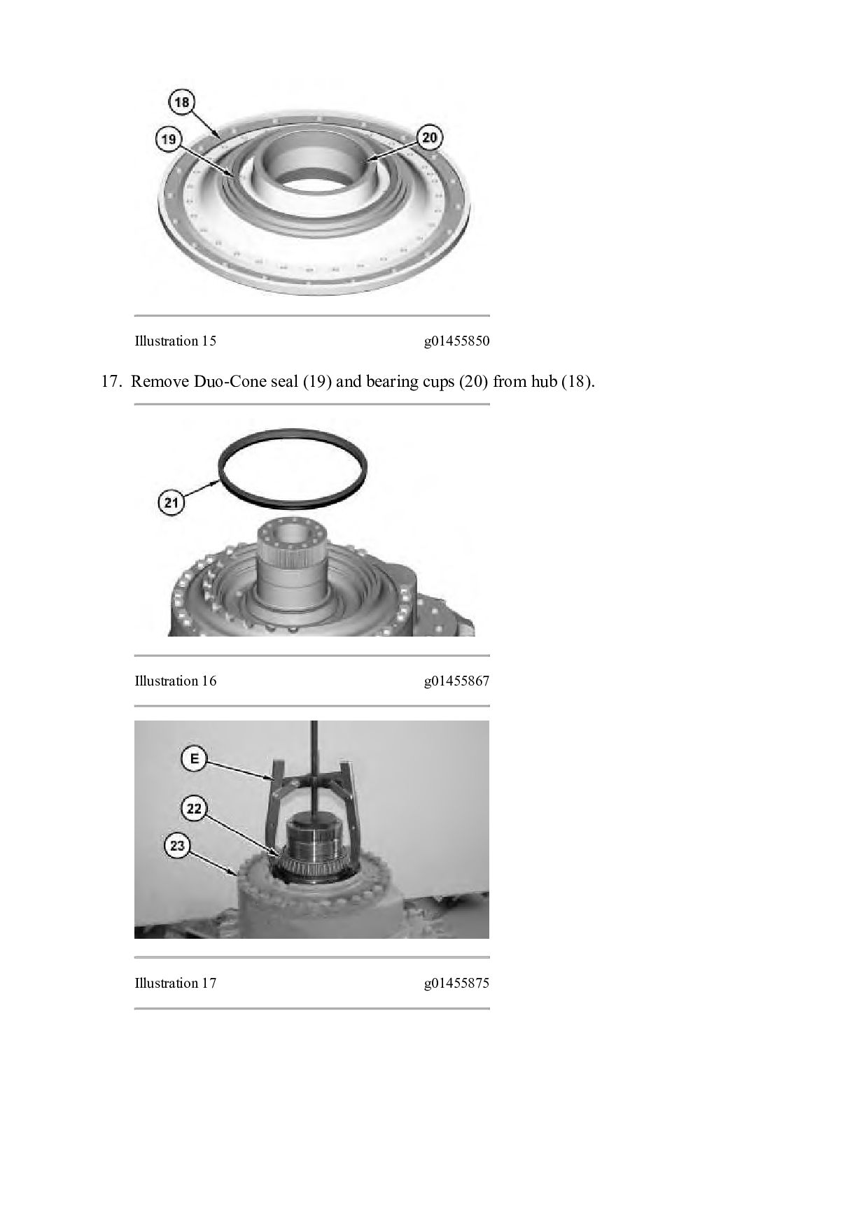
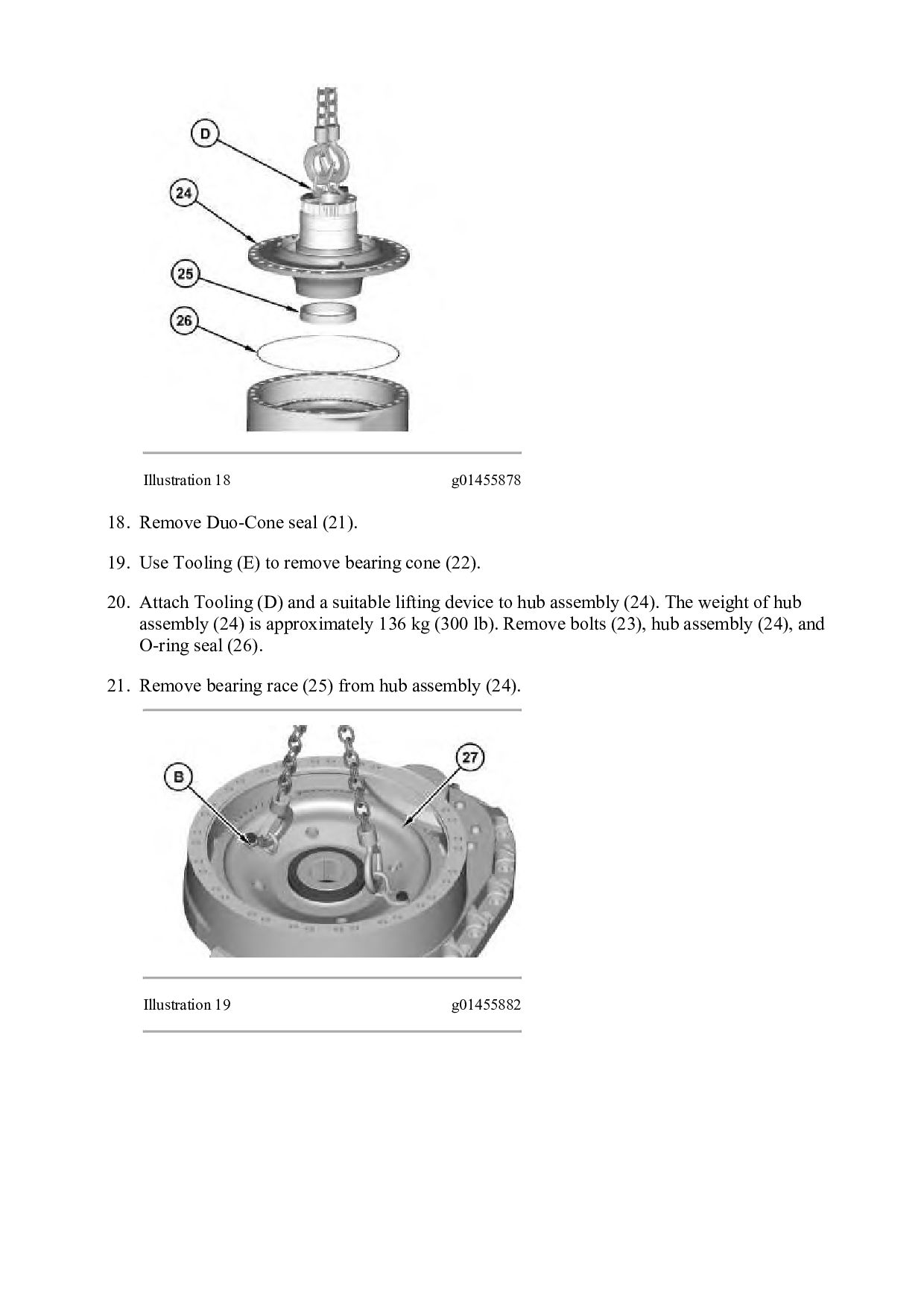
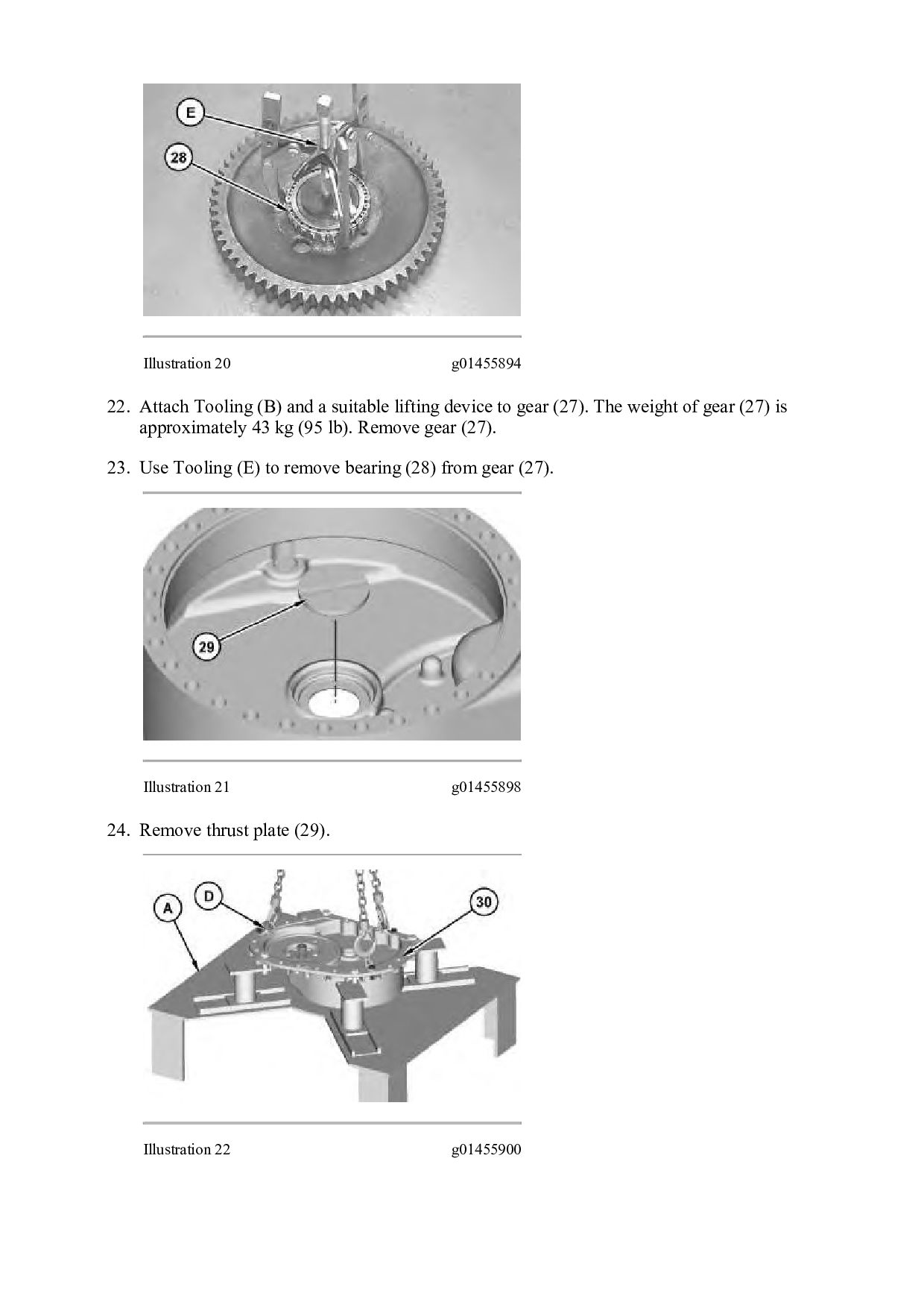
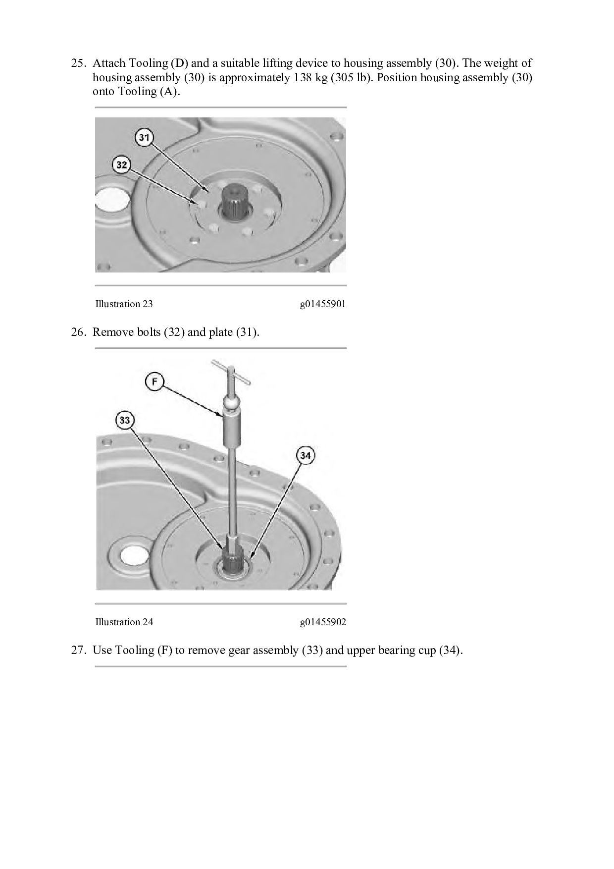
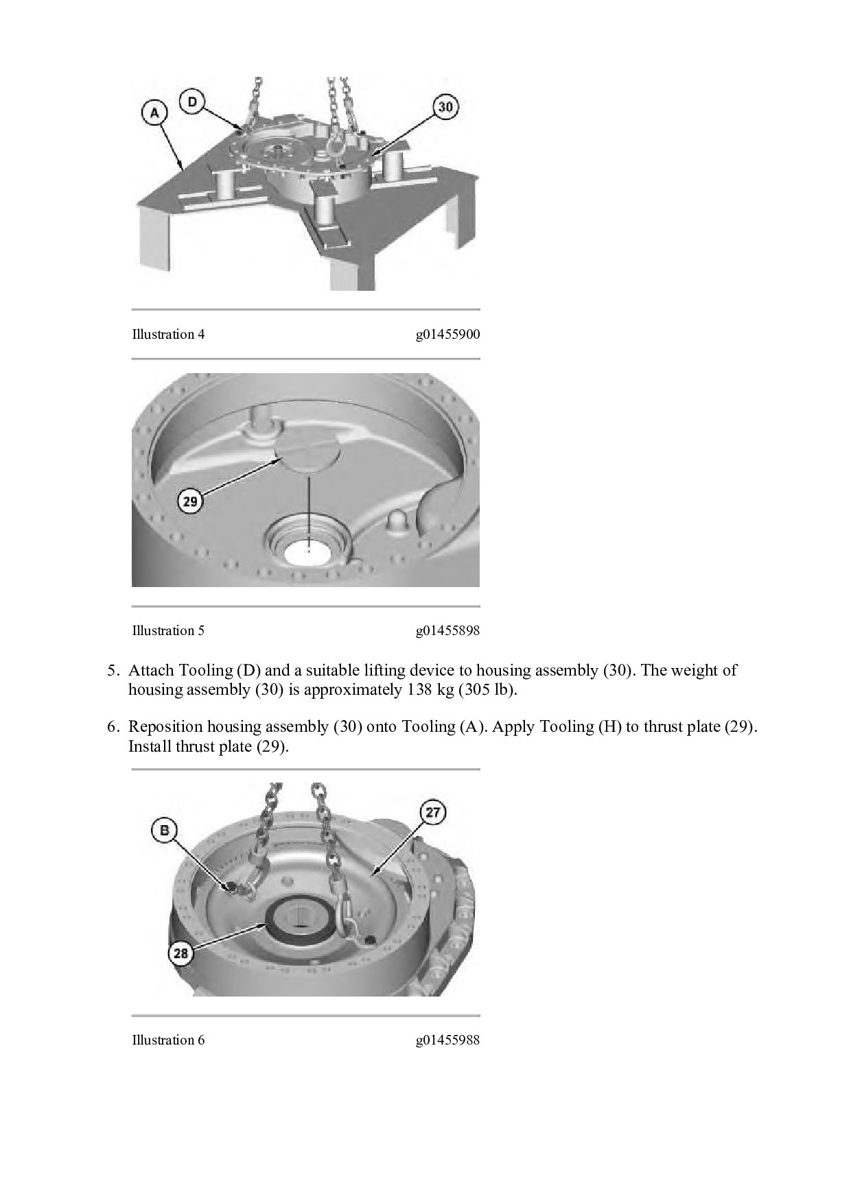
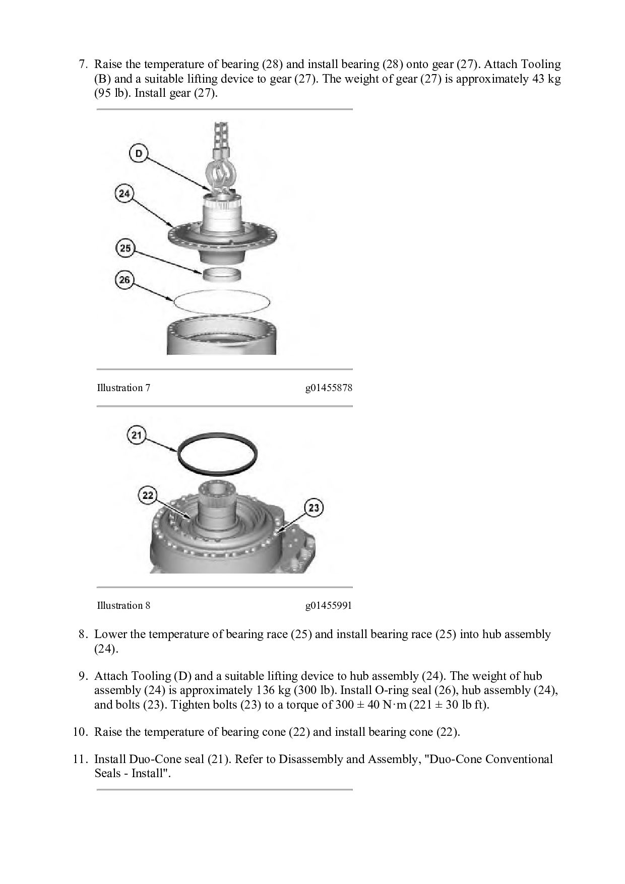
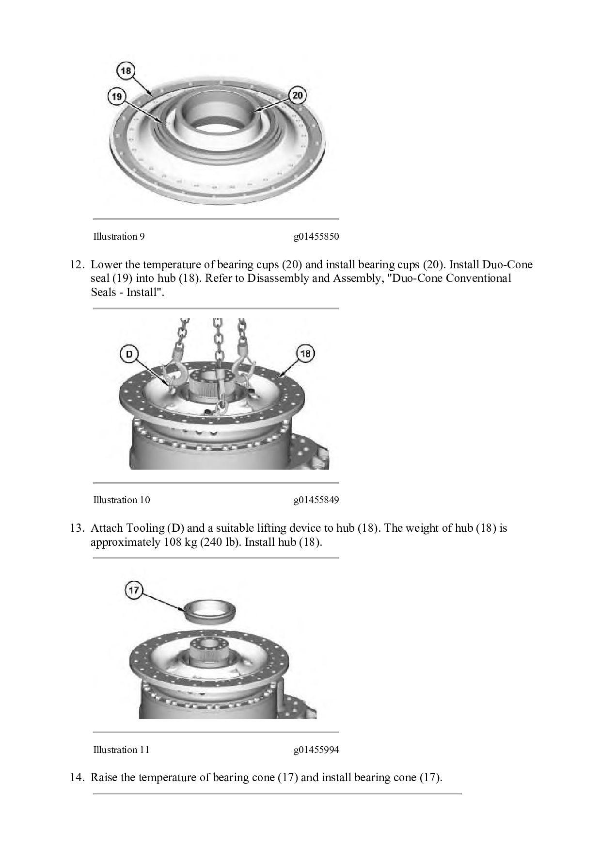
    (28) onto gear (27). Attach Tooling (B) and a suitable lifting device to gear (27). The weight of gear (27) is approximately 43 kg (95 lb). Install gear (27). Illustration 7 g01455878 Illustration 8 g01455991 8. Lower the temperature of bearing race (25) and install bearing race (25) into hub assembly (24). 9. Attach Tooling (D) and a suitable lifting device to hub assembly (24). The weight of hub assembly (24) is approximately 136 kg (300 lb). Install O-ring seal (26), hub assembly (24), and bolts (23). Tighten bolts (23) to a torque of 300 ± 40 N·m (221 ± 30 lb ft). 10. Raise the temperature of bearing cone (22) and install bearing cone (22). 11. Install Duo-Cone seal (21). Refer to Disassembly and Assembly, "Duo-Cone Conventional Seals - Install".
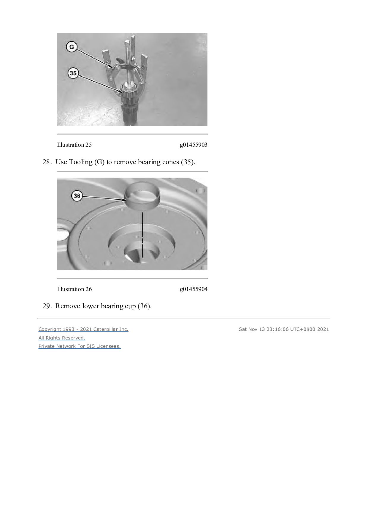
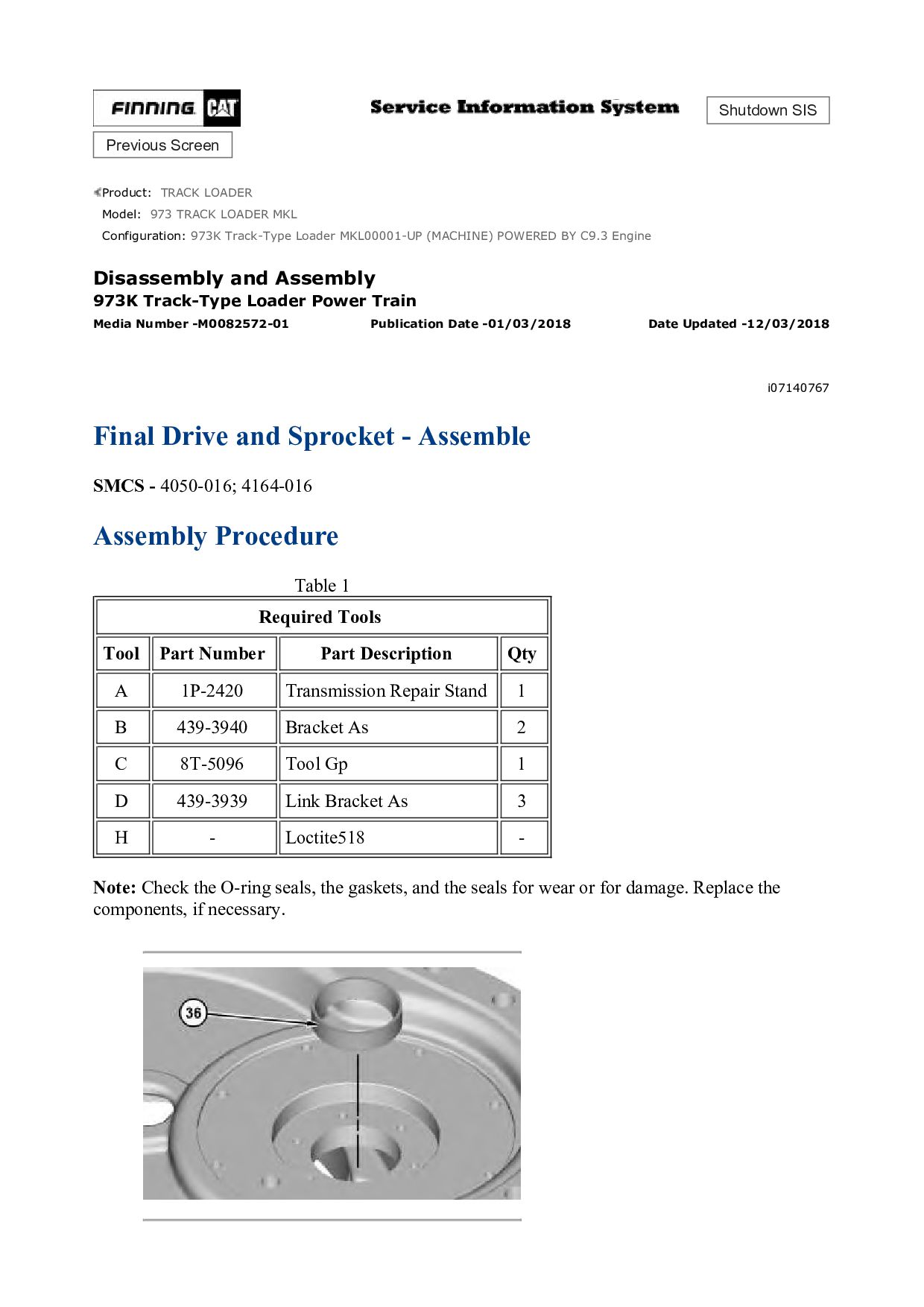
  18. Illustration 9 g01455850 12. Lower the temperature of bearing cups

    (20) and install bearing cups (20). Install Duo-Cone seal (19) into hub (18). Refer to Disassembly and Assembly, "Duo-Cone Conventional Seals - Install". Illustration 10 g01455849 13. Attach Tooling (D) and a suitable lifting device to hub (18). The weight of hub (18) is approximately 108 kg (240 lb). Install hub (18). Illustration 11 g01455994 14. Raise the temperature of bearing cone (17) and install bearing cone (17).
  19. Illustration 12 g01455801 15. Attach a suitable lifting device to

    ring gear (16). The weight of ring gear (16) is approximately 68 kg (150 lb). Install ring gear (16). Illustration 13 g01456000 16. Position retainer (15) and install bolts (14). To properly seat bearing cone (17), continually rotate hub (18). Tighten all bolts (14) in a star pattern. Tighten bolts (14) to a torque of 300 ± 40 N·m (221 ± 30 lb ft).
  20. Illustration 14 g01297505 17. Lower the temperature of bearing cups

    (13) and install bearing cups (13). Illustration 15 g01363846 18. Install shaft (10). Raise the temperature of bearing cone (11) and install bearing cone (11). Install gear (12). Raise the temperature of remaining bearing cone (11) and install bearing cone (11). Repeat for the remaining gear and shaft assemblies (12). 19. Position plate (9) and install bolts (8).
  21. Illustration 16 g01363270 20. Attach Tooling (B) and a suitable

    lifting device to position housing assembly (6). The weight of housing assembly (6) is approximately 136 kg (300 lb). Install bolts (7). Tighten bolts (7) to a torque of 300 ± 40 N·m (221 ± 30 lb ft). Illustration 17 g01363268 21. Install sun gear (5). Illustration 18 g01363258 22. Apply Tooling (H) to cover (4). Position cover (4) and install bolts (3).
  22. Illustration 19 g01291250 23. Lubricate bolts (1) with clean oil.

    Position sprocket segments (2) and install bolts (1). Tighten bolts (1) to a torque of 300 ± 55 N·m (221 ± 41 lb ft). Torque bolts an extra 1/3 turn. Illustration 20 g01291262 24. Attach a suitable lifting device to the final drive. The weight of the final drive is approximately 748 kg (1650 lb). Remove the final drive from Tooling (A). End By: a. Install the track brakes. b. Install the final drive and the sprocket. Copyright 1993 - 2021 Caterpillar Inc. All Rights Reserved. Private Network For SIS Licensees. Sat Nov 13 23:17:01 UTC+0800 2021
  23. Shutdown SIS Previous Screen Product: TRACK LOADER Model: 973 TRACK

    LOADER MKL Configuration: 973K Track-Type Loader MKL00001-UP (MACHINE) POWERED BY C9.3 Engine Disassembly and Assembly 973K Track-Type Loader Power Train Media Number -M0082572-01 Publication Date -01/03/2018 Date Updated -12/03/2018 i07162640 Track Brake - Remove and Install SMCS - 4251-010 Removal Procedure Table 1 Required Tools Tool Part Number Part Description Qty A - Guide Studs M12 x 1.75 by 290mm 2 Start By: a. Remove the track drive motor. Illustration 1 g01457893 1. Disconnect hose assembly (1). Remove two bolts (2).
  24. Illustration 2 g01457894 2. Install Tooling (A) to remove track

    brake (3). Use two people to remove track brake (3). The weight of track brake (3) is approximately 36 kg (80 lb). Remove the remaining bolts (2) and track brake (3). Illustration 3 g01457895 3. Remove shaft (7), friction discs (5), plates (6), and ring gear (4). Illustration 4 g01458025 4. Remove O-ring seals (8) from ring gear (4).
  25. Installation Procedure Table 2 Required Tools Tool Part Number Part

    Description Qty A - Guide Studs M12 x 1.75 by 290mm 2 Illustration 5 g01458025 1. Install O-ring seals (8) onto ring gear (4). Illustration 6 g01458072
  26. Illustration 7 g01457895 2. Install Tooling (A) to install ring

    gear (4) and the track brake. Install ring gear (4) and shaft (7). Note: Make sure that ring gear (4) is installed against the case. 3. Prior to assembly, dip friction disc (5) and plates (6) in SAE 30w oil. Install friction disc (5) and plates (6). Illustration 8 g01457894 4. Use two people to install track brake (3). The weight of track brake (3) is approximately 36 kg (80 lb). Position track brake (3) and install bolts (2). 5. Remove Tooling (A).
  27. Illustration 9 g01457893 6. Install the remaining bolts (2). Connect

    hose assembly (1). End By: a. Install the track drive motor. Copyright 1993 - 2021 Caterpillar Inc. All Rights Reserved. Private Network For SIS Licensees. Sat Nov 13 23:17:57 UTC+0800 2021
  28. Shutdown SIS Previous Screen Product: TRACK LOADER Model: 973 TRACK

    LOADER MKL Configuration: 973K Track-Type Loader MKL00001-UP (MACHINE) POWERED BY C9.3 Engine Disassembly and Assembly 973K Track-Type Loader Power Train Media Number -M0082572-01 Publication Date -01/03/2018 Date Updated -12/03/2018 i02938344 Track Brake - Disassemble SMCS - 4251-015 Disassembly Procedure Table 1 Required Tools Tool Part Number Part Description Qty A 6V-4035 Sleeve 1 B 170-5409 Driver 1 C 1P-0520 Driver Gp 1 Start By: a. Remove the track brake. Illustration 1 g01333903
  29. Personal injury can result from being struck by parts propelled

    by a released spring force. Make sure to wear all necessary protective equipment. Follow the recommended procedure and use all recommended tooling to release the spring force. 1. Use two people to position housing (1), Tooling (A) and Tooling (B) into a suitable press. The weight of housing (1) is approximately 36 kg (80 lb). 2. Use a suitable press, Tooling (A), and Tooling (B) to compress the springs. Remove retaining ring (2). Remove Tooling (A). Illustration 2 g01333953 3. Remove plate (3). Illustration 3 g01457814
  30. 4. Remove two disc springs (4). Use two people to

    remove Tooling (B) and housing (1) from the press. The weight of housing (1) is approximately 29 kg (65 lb). Illustration 4 g01333975 5. Use Tooling (C) and a suitable press to remove piston (5). Illustration 5 g01333983 6. Remove seals (6). Copyright 1993 - 2021 Caterpillar Inc. All Rights Reserved. Private Network For SIS Licensees. Sat Nov 13 23:18:53 UTC+0800 2021
  31. Thank you very much for your reading. Please Click Here.

    Then Get COMPLETE MANUAL. NO WAITING NOTE: If there is no response to click on the link above, please download the PDF document first and then click on it.
  32. Shutdown SIS Previous Screen Product: TRACK LOADER Model: 973 TRACK

    LOADER MKL Configuration: 973K Track-Type Loader MKL00001-UP (MACHINE) POWERED BY C9.3 Engine Disassembly and Assembly 973K Track-Type Loader Power Train Media Number -M0082572-01 Publication Date -01/03/2018 Date Updated -12/03/2018 i07140778 Track Brake - Assemble SMCS - 4251-016 Assembly Procedure Table 1 Required Tools Tools Part Number Part Description Qty A 6V-4035 Sleeve 1 B 170-5409 Driver 1 C 1P-0520 Driver Gp 1 Note: Check seals and springs for wear or damage. Replace the components, if necessary. Illustration 1 g01333983 1. Install seals (6).
  33. Note: Lightly lubricate seals with SAE 30 Oil. Illustration 2

    g01334004 2. Use Tooling (C) and a suitable press to install piston (5). Illustration 3 g01457814 3. Use two people to place housing (1) and Tooling (B) into a suitable press. The weight of housing (1) is approximately 29 kg (65 lb). 4. Install two disc springs (4). Note: Lightly lubricate springs with SAE 30 Oil.
  34. Illustration 4 g01333953 5. Install plate (3). Illustration 5 g01333903

    Improper assembly of parts that are spring loaded can cause bodily injury. To prevent possible injury, follow the established assembly procedure and wear protective equipment. 6. Use Tooling (A), Tooling (B), and a suitable press to install retaining ring (2). 7. Install retaining ring (2). 8. Remove Tooling (A). Use two people to remove housing (1) from the suitable press. The weight of the housing (1) is approximately 36 kg (80 lb). End By: a. Install the track brake.
  35. https://www.aservicemanualpdf.com/ My Dear Friend! Thank you very much for visiting.

    Full manual if required, please enter the following URL into your browser. https://www.aservicemanualpdf.com/