Upgrade to Pro — share decks privately, control downloads, hide ads and more …

Caterpillar_Cat_980F_WHEEL_LOADER__Prefix_5XJ__Service_Repair_Manual__5XJ00617-00712_.pdf

dcfv
May 20, 2024
5

 Caterpillar_Cat_980F_WHEEL_LOADER__Prefix_5XJ__Service_Repair_Manual__5XJ00617-00712_.pdf

dcfv

May 20, 2024
Tweet

More Decks by dcfv

Transcript

  1. Shutdown SIS Previous Screen Product: WHEEL LOADER Model: 980F WHEEL

    LOADER 5XJ Configuration: 980 F SERIES II WHEEL LOADER 5XJ00617-00712 (MACHINE) POWERED BY 3406 ENGINE Disassembly and Assembly 980F & 980F SERIES II WHEEL LOADERS POWER TRAIN Media Number -SENR4991-02 Publication Date -01/08/2004 Date Updated -18/04/2012 SENR49910028 Transmission SMCS - 3150-016; 3150-015 Disassemble Transmission
  2. Start By: a. separate transmission from transfer gears b. remove

    transmission hydraulic control valves 1. Fasten tool (B) and a hoist to the transmission as shown. 2. Put the transmission in position on tool (A). The weight of the transmission is 567 kg (1250 lb). 3. Fasten tool (B) and a hoist to planetary group (1). Remove bolts (3) that hold transmission case (2) to planetary group (1). 4. Install two 1/2" - 13 NC forcing screws (4) in the transmission case. 5. Use the hoist and forcing screws (4) to remove planetary group (1) from transmission case (2). The weight of the planetary group is 424 kg (935 lb). 6. Use tool (B) and a hoist to remove the transmission case from tool (A). The weight of the transmission case is 143 kg (315 lb).
  3. 7. Put planetary group (1) in position on tool (A)

    as shown. Fasten the planetary group to tool (A) with suitable size bolts, washers and nuts. 8. Remove two O-ring seals (5) and O-ring seal (6) from the manifold assembly. 9. Put an alignment mark across the clutch housing assemblies of the planetary group for assembly purposes. 10. Remove bolts (7) and the washers from the No. 6 clutch housing. 11. Use tool (C) to hold the clutch piston in No. 6 clutch housing (8). 12. Fasten tool (B) and a hoist to No. 6 clutch housing (8). Remove No. 6 clutch housing (8) from the manifold assembly. The weight of the No. 6 clutch housing is 29 kg (64 lb). 13. Remove reaction dowels (10) and clutch piston (9) from No. 6 clutch housing (8).
  4. 14. Remove seal rings (11) from clutch piston (9). 15.

    Remove five dowels (12) and springs (13) from the manifold assembly. NOTICE Keep the friction discs and clutch plates for the individual clutches in their original sequence and with their respective clutch housings. 16. Remove three friction discs (14) and two clutch plates (15) from the manifold assembly. 17. Remove ring gear (16) from the manifold assembly.
  5. https://www.aservicemanualpdf.com/ My Dear Friend! Thank you very much for visiting.

    Full manual if required, please enter the following URL into your browser. https://www.aservicemanualpdf.com/
  6. 18. Use tool (D), and remove retaining ring (17) from

    the output shaft assembly. 19. Remove carrier assembly (18) from the manifold assembly. 20. Disassemble carrier assembly (18) as follows: a. Remove seal ring (19) from the carrier. b. Use a hammer and a punch to push spring pin (21) into planetary shaft (20).
  7. c. Remove planetary shaft (20), thrust disc (26), planetary gear

    (24) and thrust (22) from the carrier. d. Remove bearings (23) and (25) from planetary gear (24). e. Remove spring pin (21) from planetary shaft (20). f. Disassemble the remainder of carrier assembly (18) as in Steps 20b through 20e. 21. Remove retaining ring (28) from the housing assembly. 22. Remove sun gear (27) from the output shaft assembly. NOTE: After retaining ring (29) has been removed, the housing assembly will drop a small amount into the manifold assembly. 23. Use tool (E), and remove retaining ring (29) from the housing assembly. 24. Fasten tool (F) and a hoist to manifold assembly (31) as shown. Remove manifold assembly (31) from the No. 3 and 4 clutch housing. The weight of the manifold assembly is 88 kg (194 lb).
  8. 25. Remove dowel (32) and O-ring seal (33) from the

    manifold assembly. 26. Use tool (G), and remove retaining ring (34) from the manifold assembly. 27. Use tool (H) to remove bearing (35) from the manifold assembly. 28. Remove springs (36) from the clutch piston. 29. Remove retaining ring (37) from the groove in ring gear (38).
  9. 30. Remove housing assembly (39) from ring gear (38). 31.

    Use tool (J) and a press to compress the three disc springs in the housing assembly. 32. Use tool (K), and remove retaining ring (40) from the housing assembly. 33. Remove retainer plate (41), and three disc springs (42) from the housing assembly. 34. Remove clutch piston (43) from the housing assembly.
  10. 35. Remove seal rings (44) from clutch piston (43). 36.

    Remove seal rings (46) from ring carrier (45). NOTE: Ring carrier (45) must be destroyed during removal. Do not remove the ring carrier unless it is worn or damaged. NOTICE Do not push dowel (47) into the housing assembly to remove the ring carrier. 37. Use a hammer and chisel to break the ring carrier, and remove it from the housing. After the ring carrier is removed, remove dowel (47) from the housing assembly. 38. Remove ring gear (38) from the No. 3 and 4 clutch housing.
  11. 39. Remove four friction discs (48) and three clutch plates

    from ring gear (38). 40. Remove reaction plate (49) from ring gear (38). 41. Remove reaction dowels (51) from the No. 3 and 4 clutch housing. 42. Remove two friction discs (50) and one clutch plate from No. 3 and 4 clutch housing. 43. Use tool (L) to hold the two clutch pistons in No. 3 and 4 clutch housing (53) as shown. 44. Install two 5/8" - 11 NC forged eyebolts (52) in the No. 3 and 4 clutch housing (53). Fasten a hoist to the eyebolts, and remove No. 3 and 4 clutch housing (53) from the No. 2 clutch housing. The weight of the No. 3 and 4 clutch housing is 52 kg (115 lb).
  12. 45. Remove clutch piston (54) from the No. 3 and

    4 clutch housing. 46. Remove seal rings (55) from clutch piston (54). 47. Turn the No. 3 and 4 clutch housing over. 48. Remove clutch piston (56) from the No. 3 and 4 clutch housing. 49. Remove seal rings (57) from clutch piston (56).
  13. 50. Remove ten bolt dampers (58) and reaction dowels (59)

    from both sides of the No. 3 and 4 clutch housing. 51. Remove springs (61) from the No. 2 clutch housing. 52. Remove three friction discs (60) and the two clutch plates from the No. 2 clutch housing. 53. Use tool (D), and remove retaining ring (62) from the output shaft. 54. Remove clutch hub (63) from the carrier assembly. 55. Remove carrier assembly (64) and the ring gear as a unit from the No. 2 clutch housing.
  14. 56. Remove sun gear (65) from the carrier assembly. 57.

    Use 2.79 mm (.110 in) diameter roll pins (66) to put the lock ring under compression that holds carrier assembly (64) and ring gear (67) together. Remove carrier assembly (64) from ring gear (67). 58. Remove the lock ring from the carrier assembly. 59. Disassemble carrier assembly (64) as follows: a. Remove retaining ring (68) from the carrier assembly. b. Use tool group (H), and remove the bearing from carrier assembly (64).
  15. c. Use a hammer and a punch to push spring

    pin (70) into planetary shaft (69). d. Remove planetary shaft (69), thrust disc (71), planetary gear (72) and thrust disc (74) from the carrier. e. Remove bearing (73) from planetary gear (72). f. Remove spring pin (70) from planetary shaft (69). g. Disassemble the remainder of carrier assembly (64) as in Steps 59c through 59f. 60. Remove bolts (75) that hold the No. 2 clutch housing (76) to the No. 1 clutch housing. 61. Use tool (C) to hold clutch piston (77) in No. 2 clutch housing (76). 62. Fasten two of tool (B) and a hoist to No. 2 clutch housing (76). Remove No. 2 clutch housing (76) from the plate assembly. The weight of the No. 2 clutch housing is 27 kg (60 lb).
  16. 63. Remove clutch piston (77) from No. 2 clutch housing

    (76). 64. Remove seal rings (78) from clutch piston (77). 65. Remove dowels (80) and springs (79) from the plate assembly. 66. Remove five friction discs (81) and four clutch plates (82) from the plate assembly. 67. Remove ring gear (83) from the plate assembly.
  17. 68. Remove retaining ring (84) that holds output shaft assembly

    (85) in the carrier assembly. 69. Remove output shaft assembly (85) from the carrier assembly. 70. Use tool (D) to remove retaining ring (86) from the output shaft assembly. 71. Remove sun gear (87) from the output shaft assembly. 72. Use tooling (M) and a press to remove bearing (88) from the output shaft assembly.
  18. NOTE: The sleeve bearing used in each end of the

    output shaft has a different part number. Put an identification mark on each sleeve bearing as to its location in the output shaft. 73. Remove sleeve bearings (89) from each end of the output shaft assembly (85). 74. Use tool (D) to remove retaining ring (91) from shaft assembly (90). 75. Remove carrier assembly (92) from the No. 1 clutch housing. 76. Remove sun gear (93) from the carrier assembly. 77. Put a small block under carrier assembly (92) so ring gear (95) can be lowered after the retaining ring is compressed. 78. Use 3.18 mm (.125 in) diameter roll pins (94) to put the lock ring under compression that holds carrier assembly (92) to ring gear (95). Lower ring gear (95) from carrier assembly (92). 79. Disassemble carrier assembly (92) as follows:
  19. a. Use a hammer and a punch to push the

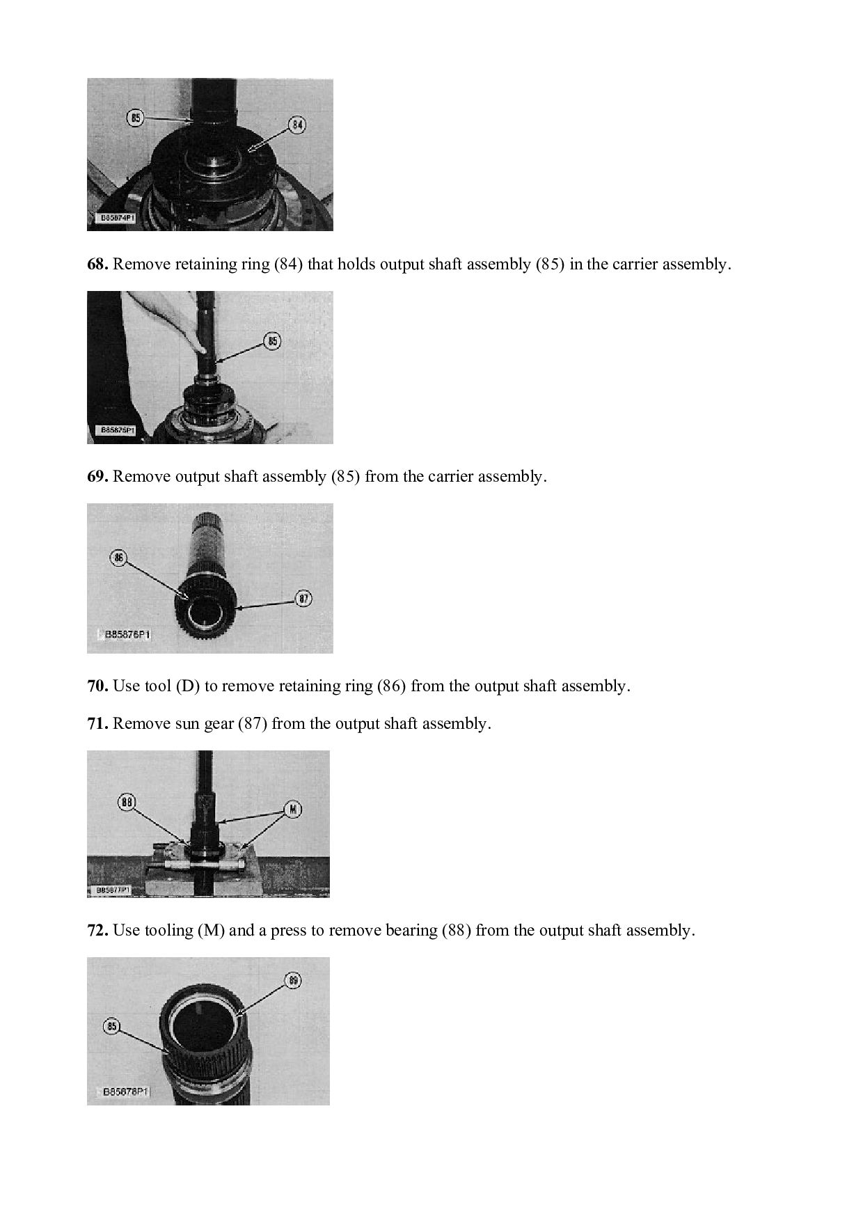
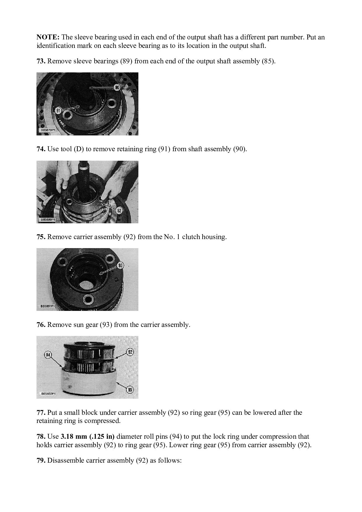
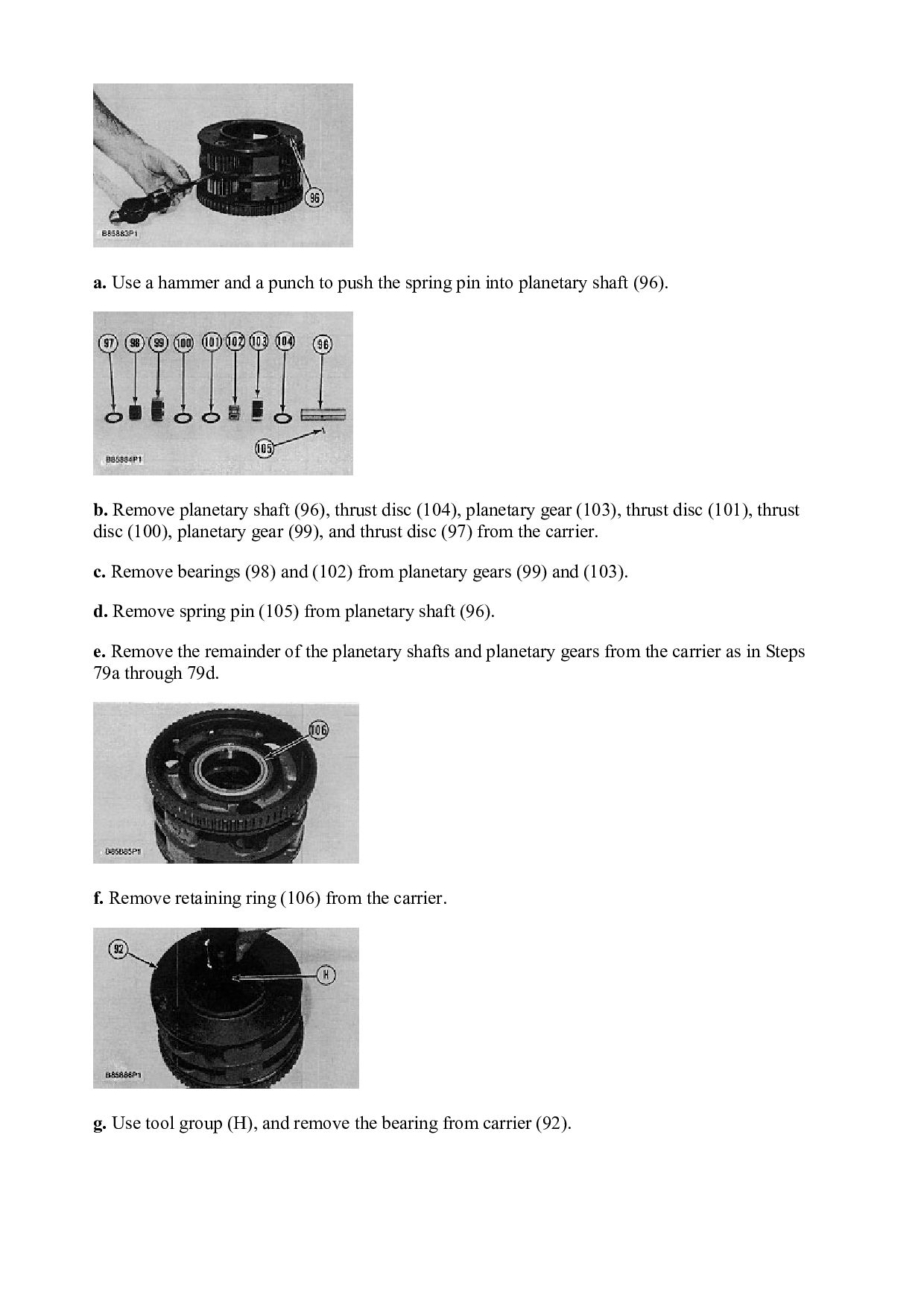
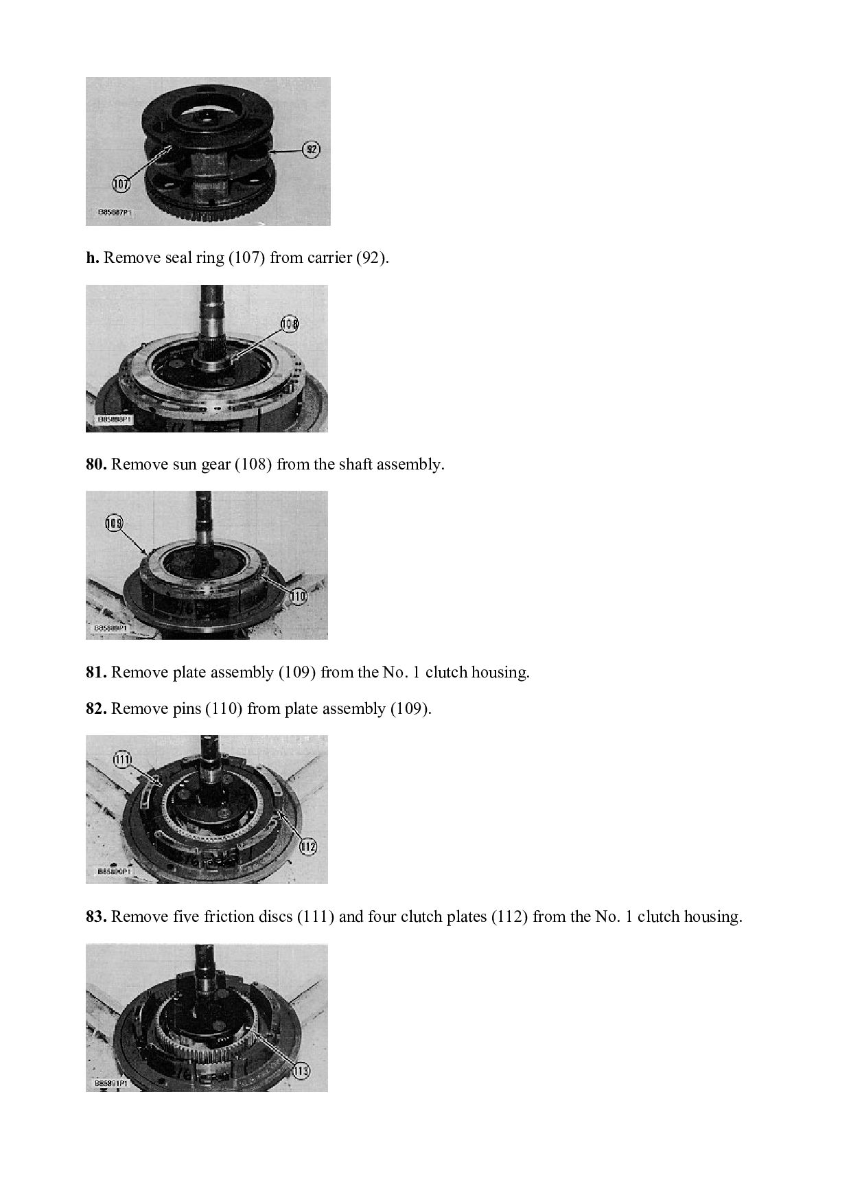
    spring pin into planetary shaft (96). b. Remove planetary shaft (96), thrust disc (104), planetary gear (103), thrust disc (101), thrust disc (100), planetary gear (99), and thrust disc (97) from the carrier. c. Remove bearings (98) and (102) from planetary gears (99) and (103). d. Remove spring pin (105) from planetary shaft (96). e. Remove the remainder of the planetary shafts and planetary gears from the carrier as in Steps 79a through 79d. f. Remove retaining ring (106) from the carrier. g. Use tool group (H), and remove the bearing from carrier (92).
  20. h. Remove seal ring (107) from carrier (92). 80. Remove

    sun gear (108) from the shaft assembly. 81. Remove plate assembly (109) from the No. 1 clutch housing. 82. Remove pins (110) from plate assembly (109). 83. Remove five friction discs (111) and four clutch plates (112) from the No. 1 clutch housing.
  21. 84. Remove coupling (113) from the No. 1 clutch housing.

    85. Use tool (N) to remove retaining ring (114) from the shaft assembly on the bottom side of the No. 1 clutch housing. 86. Remove shaft assembly (90) from the No. 1 clutch housing. 87. Use tool (D), and remove retaining ring (115) from the carrier assembly. 88. Remove carrier assembly (116) from the No. 1 clutch housing. 89. Disassemble carrier assembly (116) as follows:
  22. a. Remove lock ring (117) from the carrier assembly. b.

    Use a hammer and a punch to push spring pin (119) into planetary shaft (118). c. Remove planetary shaft (118), thrust disc (123), planetary gear (121) and thrust disc (120) from the carrier. d. Remove bearing (122) from planetary gear (121). e. Remove spring pin (119) from planetary shaft (118). f. Remove the remainder of the planetary shafts and planetary gears from the carrier as in Steps 89b through 89e. g. Remove ring carrier (124) from the carrier.
  23. h. Remove metal seal ring (125) from ring carrier (124).

    j. Remove retaining ring (126) from the carrier. k. Use tool (H), and remove the bearing from carrier (116). l. Remove metal seal ring (129) from ring carrier (127). m. Remove dowel (128) and ring carrier (127) from the carrier.
  24. 90. Remove clutch piston (130) from the No. 1 clutch

    housing. 91. Remove seal rings (131) from clutch piston (130). 92. Use tool (G), and remove retaining ring (132) from the No. 1 clutch housing. 93. Use tool (H), and remove the bearing from the No. 1 clutch housing. Assemble Transmission
  25. NOTE: Check all parts of the transmission for wear or

    damage. If any of the parts are worn or damaged, use new parts for replacement. During assembly, put clean transmission oil on all parts. Figure 1 1. There is a correct method to make non-metal rotating type rings ready for installation. Use your hands on each end of the ring to pull the ends several inches by each other. Figure 1. Use care to keep the ring shape like a circle. This make an even bend (or ring "set") all the way around the ring. When the ring is in the groove, the notches in the ends must be fully engaged with each other so the ring will not make contact with the edge of cage bore. That is, the notches must be fully engaged and the ends must be together. See Figure 2. Figure 2 NOTICE Do not bend the ring as shown in Figure 3. This does not make an even bend all the way around the ring.
  26. Figure 3 2. If necessary, lower the temperature of bearing

    (3). Using tool (B), install bearing (3) in No. 1 clutch housing (1) until it makes contact with the counterbore in the clutch housing. Be sure notch (2) in the bearing is installed up as shown. 3. Use tool (C), and install retaining ring (4) into the groove of the No. 1 clutch housing as shown. The retaining ring holds bearing (3) in position. 4. Install seal rings (6) on clutch piston (5). Be sure the lips of the seals are installed up as shown.
  27. 5. Put clean transmission oil on seal rings (6). Install

    clutch piston (5) in the No. 1 clutch housing as shown. 6. Assemble carrier assembly (10) as follows: a. Heat ring carrier (7) to a maximum temperature of 135°C (275°F), and install it on the carrier. b. Install dowel (8) in the carrier until it protrudes 2.87 ± .13 mm (.113 ± .005 in) above the outside surface. c. Install metal seal ring (9) on ring carrier (7). d. If necessary, lower the temperature of the bearing. Use tool group (B), and install the bearing in carrier assembly (10). Be sure the notch in the bearing is installed down (toward the inside of the carrier assembly). e. Install retaining ring (11) into the groove of the carrier assembly.
  28. f. Install metal seal ring (13) on ring carrier (12).

    g. Install ring carrier (12) in carrier assembly (10). Be sure notch (14) in ring carrier (12) is installed up as shown and in alignment with the notch in bearing (15). NOTICE Be sure the rubber in spring pins (21) is not damaged. If the rubber is damaged, replace the spring pins with new parts. h. Install bearing (18) in planetary gear (17). j. Put thrust disc (16), planetary gear (17), and thrust disc (19) in position in the carrier assembly (10).
  29. k. Be sure the spring pin hole in planetary shaft

    (20) is in alignment with the spring pin hole in carrier assembly (10) when installed. Install planetary shaft (20) in carrier assembly (10). l. Use a hammer and a punch to install spring pin (21) in the carrier assembly and planetary shaft. m. Install the other two planetary gears and planetary shafts in the carrier assembly as in Steps 6h through 6l. 7. Install lock ring (22) into the groove of carrier assembly (10). 8. Put the carrier assembly in position in the No. 1 clutch housing. Be sure dowel (8) is in alignment with notch (2) in the bearing. 9. Use tool (D), and install retaining ring (23) into the groove of the carrier assembly to hold the carrier assembly in place in the No. 1 clutch housing. 10. Install dowel (24) in shaft assembly (26) until it protrudes 2.88 ± .13 mm (.113 ± .005 in) above the outside surface.
  30. 11. Install pin (25) in shaft assembly (26) until it

    protrudes 6.02 ± 0.5 mm (.237 ± .02 in) above the outside surface. 12. Install shaft assembly (26) in the No. 1 clutch housing. Be sure dowel (24) and pin (25) are engaged with the notches of bearing (15) and ring carrier (12). 13. Use tool (E), and install retaining ring (27) in the groove of shaft assembly (26). 14. Install coupling (28) in the No. 1 clutch housing. 15. Install five friction discs (29) and four clutch plates (30) in the No. 1 clutch housing in alternating order. Start and end with a friction disc.
  31. 16. Install pins (31) in plate assembly (32). Be sure

    the pins (31) extend 10.0 ± 0.5 mm (.39 ± .02 in) above the outside surface on both sides of the plate assembly. 17. Install plate assembly (32) on the No. 1 clutch housings as shown. 18. Install dowel (34) until it protrudes 2.05 ± .13 mm (.081 ± .005 in) above the outside surface. 19. Install sun gear (33) on the shaft assembly. 20. Assemble carrier assembly (36) as follows: a. Install seal ring (35) on carrier (36).
  32. b. If necessary, lower the temperature of bearing (37). c.

    Use tool (B), and install bearing (37) in carrier (36). Be sure the bearing is installed with notch (39) in the bearing up. d. Install retaining ring (38) in the groove of the carrier to hold the bearing in place. NOTICE Be sure the rubber in spring pins (49) is not damaged. If the rubber is damaged, replace the spring pins with new parts. e. Install bearings (41) and (45) in planetary gears (42) and (46). f. Put thrust disc (40), planetary gear (42), and thrust disc (43) in position in the lower section of carrier (36). Put thrust disc (44), planetary gear (46) and thrust disc (47) in the upper section of carrier (36). g. Be sure the spring pin hole in planetary shaft (48) and the spring pin hole in carrier (36) are in alignment. Install planetary shaft (48) in carrier (36). h. Use a hammer and a punch to install spring pin (49) in the carrier and the planetary shaft.
  33. l. Install the remainder of the planetary shafts and planetary

    gears in carrier (36) as in Steps 20e through 20h. 21. Install lock ring (50) in the groove of carrier assembly (36). 22. Install carrier assembly (36) into ring gear (51) until lock ring (50) fits into the groove of the ring gear. 23. Put carrier assembly (36) and the ring gear as a unit in the No. 1 clutch housing as shown. Be sure notch (39) is in alignment with dowel (34) as indicated in Photo B85931P1, Step 20c. 24. Install sun gear (52) in the carrier assembly. 25. Use tool (D), and install retaining ring (53) in the groove of the shaft assembly.
  34. Thank you very much for your reading. Please Click Here.

    Then Get COMPLETE MANUAL. NO WAITING NOTE: If there is no response to click on the link above, please download the PDF document first and then click on it.
  35. 26. Install the dowel in output shaft assembly (54) until

    it protrudes 2.48 ± .13 mm (.098 ± .005 in) above the outside surface. 27. Lower the temperature of the large sleeve bearing, and put it in position in the end of output shaft assembly (54). Use tool (F) to install the bearing until it is 13.00 ± 0.25 mm (.512 ± .010 in) from the end of the shaft assembly. The inside diameter of the bearing must be 56.650 ± 0.061 mm (2.2303 ± .0024 in) after installation. 28. Turn output shaft assembly (54) over. Lower the temperature of the small sleeve bearing, and put it in position in the end of the output shaft assembly (54). Use tool group (F) to install the bearing until it is 25.50 ± 0.25 mm (1.004 ± .010 in) from the end of the shaft. The inside diameter of the bearing must be 35.629 ± 0.039 mm (1.4027 ± .0015 in) after assembly. 29. Heat bearing (55) to a maximum temperature of 135°C (275°F). Install bearing (55) on the output shaft assembly. Be sure the shoulder of the bearing is toward the end of the output shaft assembly as shown. 30. Install sun gear (57) on the output shaft assembly. 31. Use tool (D), and install retaining ring (56) in the groove of the output shaft assembly.
  36. 32. Install output shaft assembly (54) over shaft assembly (26)

    and into the carrier assembly as shown. 33. Install retaining ring (58) into the groove of the carrier assembly that holds the output shaft assembly (54) in place. 34. Put ring gear (59) in position on the plate assembly. 35. Install five friction discs (61) and four clutch plates (60) on the plate assembly in alternating order. Start with a friction disc and end with a friction disc.
  37. 36. Install springs (62) and dowels (63) through the plate

    assembly and into the No. 1 clutch housing as shown. 37. Install seal rings (64) on clutch piston (65). Be sure the lips of the seal rings are installed up as shown. 38. Put clean transmission oil on the seal rings. Install clutch piston (65) in No. 2 clutch housing (66). 39. Use tool (H) to hold clutch piston (65) in the No. 2 clutch housing (66). 40. Fasten two of tool (G), and a hoist to No. 2 clutch housing (66). Install the No. 2 clutch housing on the plate assembly. Be sure springs (62) fit correctly in the clutch pistons. 41. Install bolts (67) that hold the No. 2 clutch housing to the plate assembly and the No. 1 clutch housing. 42. Assemble carrier assembly (74) as follows:
  38. https://www.aservicemanualpdf.com/ My Dear Friend! Thank you very much for visiting.

    Full manual if required, please enter the following URL into your browser. https://www.aservicemanualpdf.com/