Upgrade to Pro — share decks privately, control downloads, hide ads and more …

Interference Coordination

George
November 30, 2020

Interference Coordination

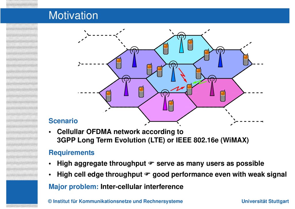
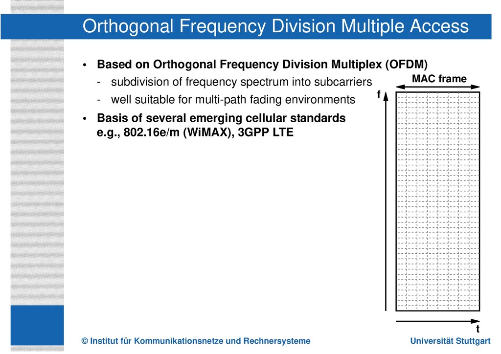
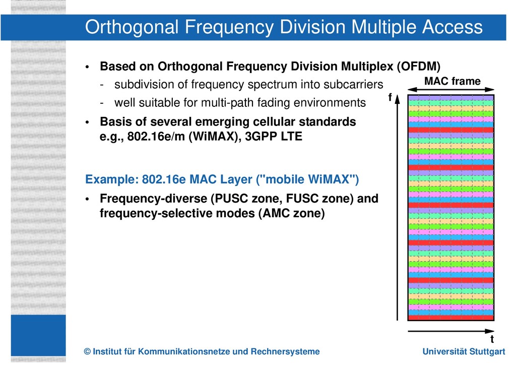
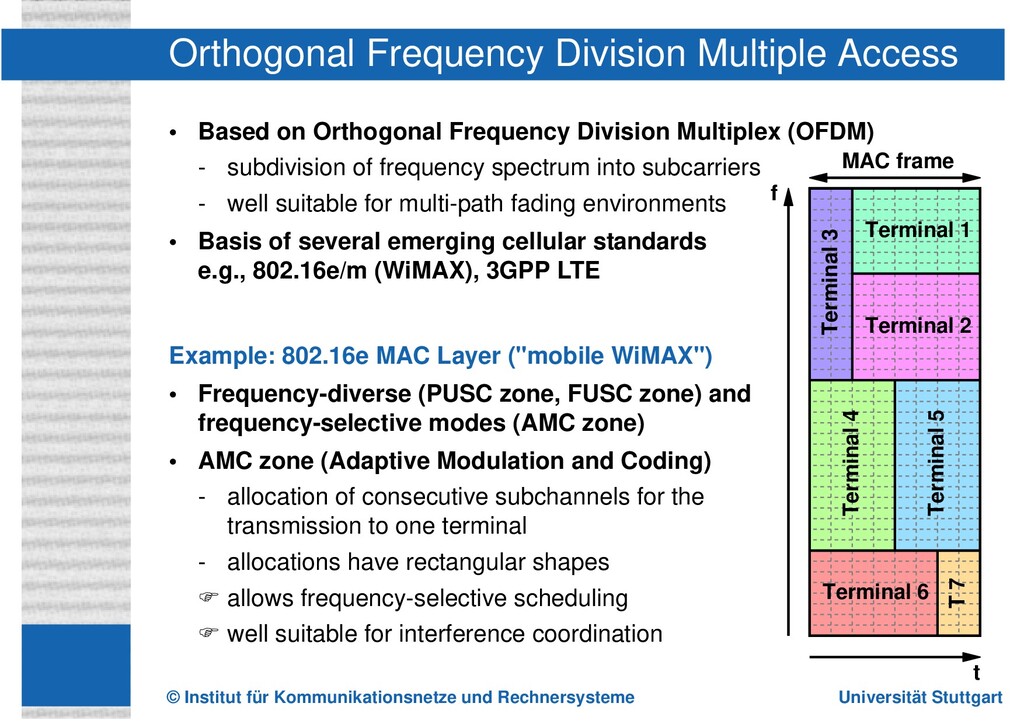
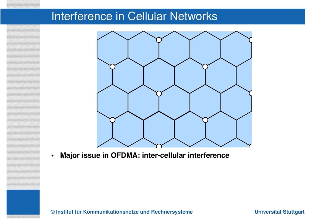
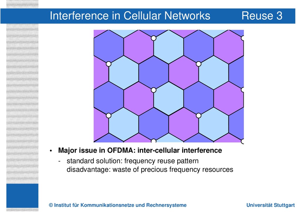
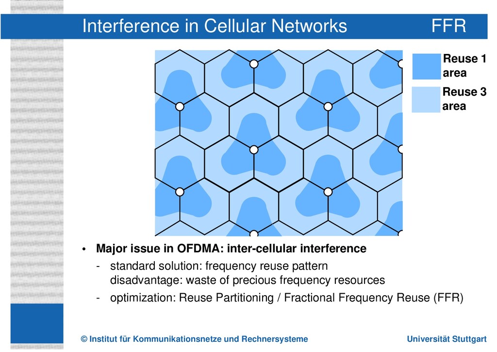
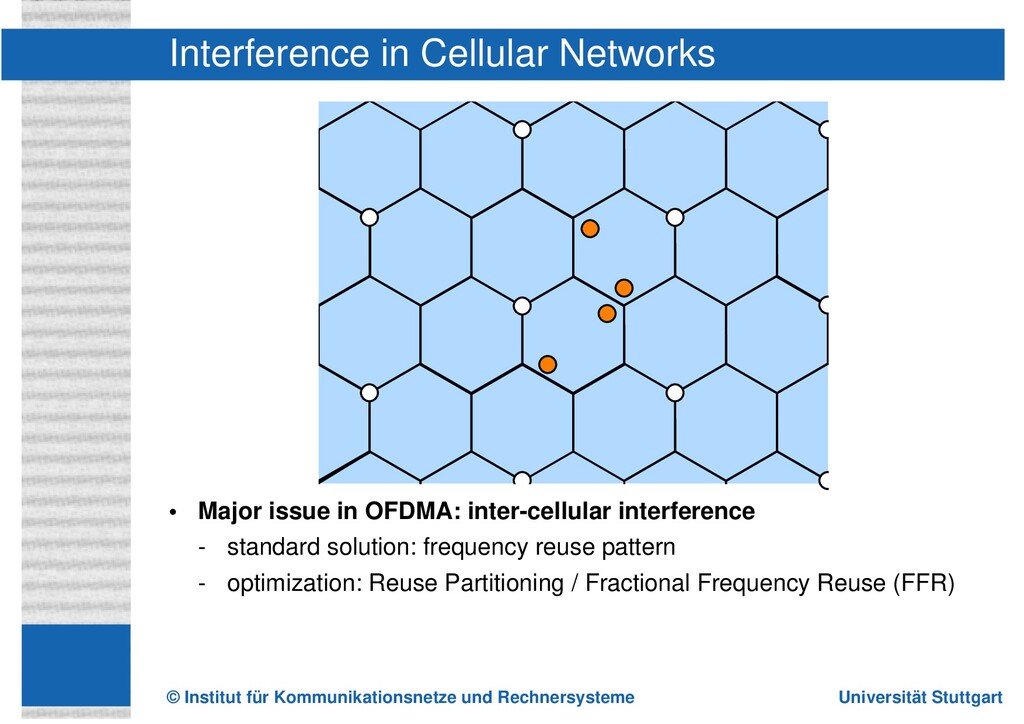
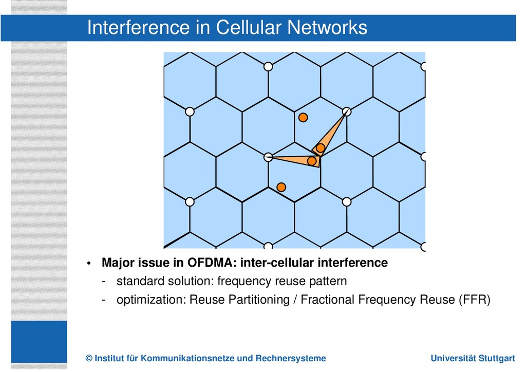
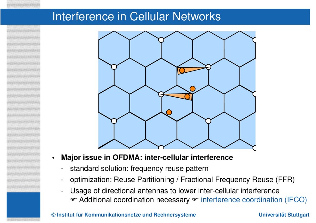
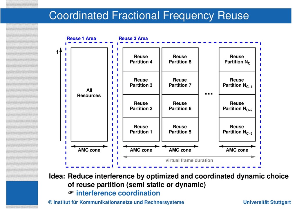
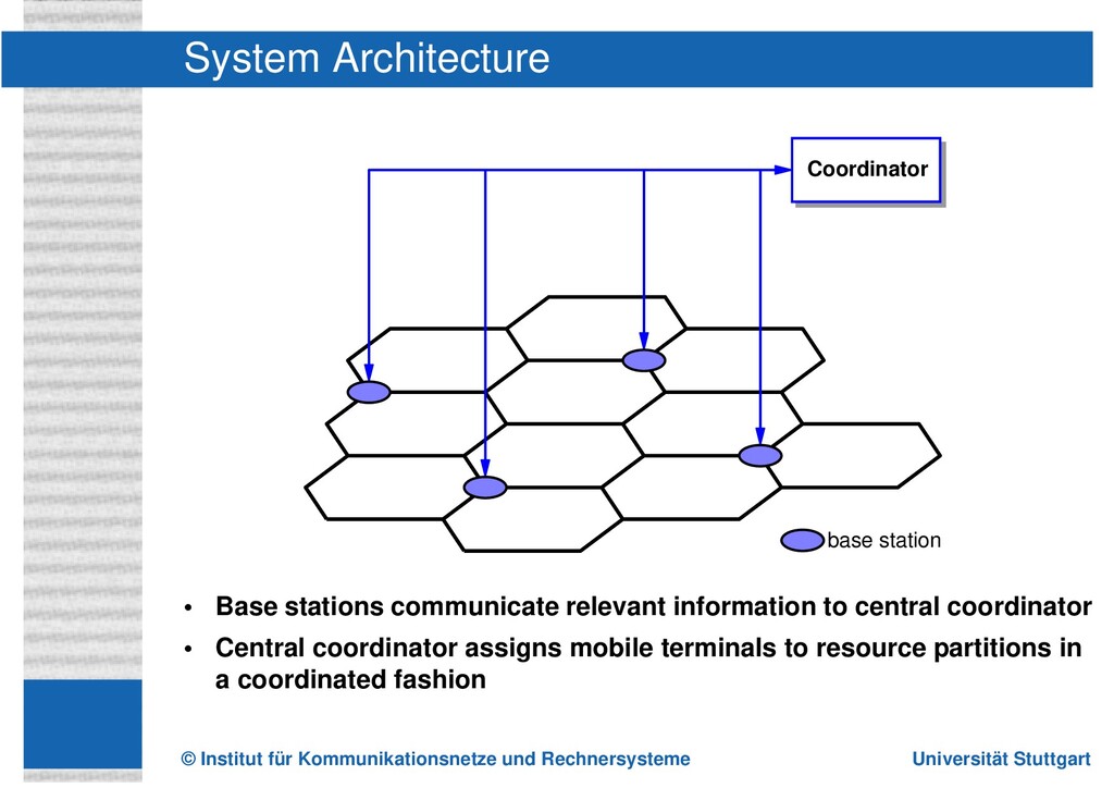
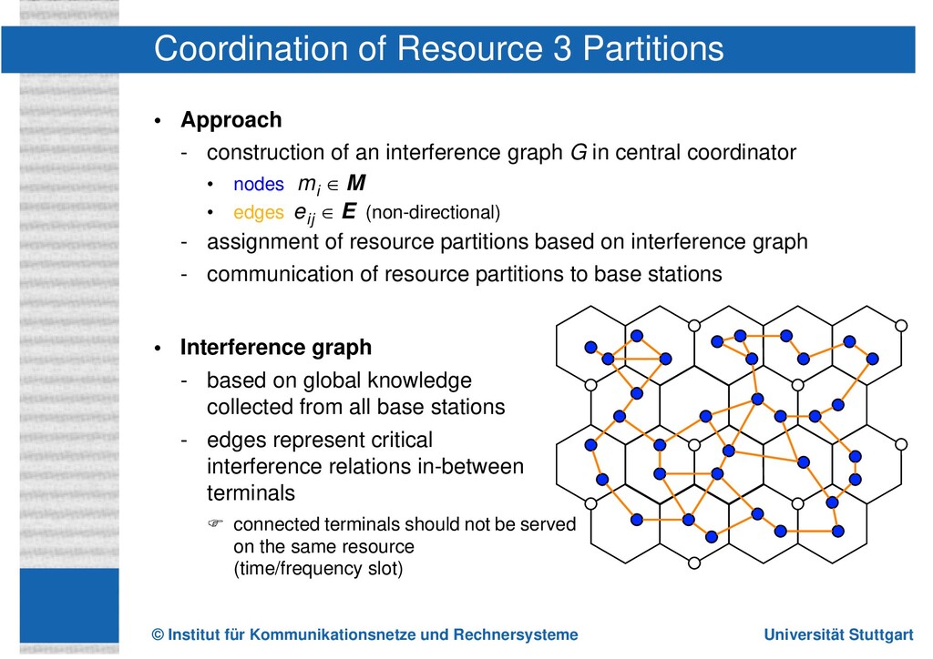
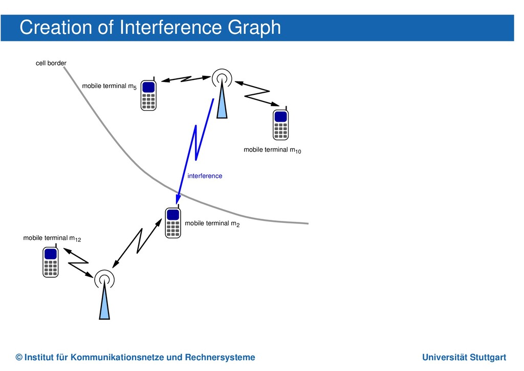
In this presentation, I give an overview over interference coordination in mobile networks. It was part of my university research. Apart from classic schemes like fractional frequency reuse, an adaptive scheme is proposed. OFDMA is one of the basic techniques in modern cellular networks.

George

November 30, 2020
Tweet

Other Decks in Research

Transcript

  1. INSTITUT FÜR KOMMUNIKATIONSNETZE UND RECHNERSYSTEME Prof. Dr.-Ing. Dr. h. c.

    mult. P. J. Kühn Universität Stuttgart Interferene Coordination in OFDMA Networks Marc Necker Institute of Communication Networks and Computer Engineering University of Stuttgart, Germany [email protected] 26. Treffen der VDE/ITG Fachgruppe 5.2.4, Düsseldorf February 28, 2008
  2. © Institut für Kommunikationsnetze und Rechnersysteme Universität Stuttgart • Introduction

    and motivation - Requirements and challenges in cellular networks - Introduction to OFDMA networks • Interference mitigation techniques - Fractional Frequency Reuse (FFR) - Interference Coordination (IFCO) • Coordinated Fractional Frequency Reuse - Concept and architecture - Algorithm description • Performance Evaluation - Comparison with conventional systems Outline
  3. © Institut für Kommunikationsnetze und Rechnersysteme Universität Stuttgart Scenario •

    Cellullar OFDMA network according to 3GPP Long Term Evolution (LTE) or IEEE 802.16e (WiMAX) Requirements • High aggregate throughput ) serve as many users as possible • High cell edge throughput ) good performance even with weak signal Major problem: Inter-cellular interference Motivation
  4. © Institut für Kommunikationsnetze und Rechnersysteme Universität Stuttgart MAC frame

    t f • Based on Orthogonal Frequency Division Multiplex (OFDM) - subdivision of frequency spectrum into subcarriers - well suitable for multi-path fading environments • Basis of several emerging cellular standards e.g., 802.16e/m (WiMAX), 3GPP LTE Orthogonal Frequency Division Multiple Access
  5. © Institut für Kommunikationsnetze und Rechnersysteme Universität Stuttgart MAC frame

    t f • Based on Orthogonal Frequency Division Multiplex (OFDM) - subdivision of frequency spectrum into subcarriers - well suitable for multi-path fading environments • Basis of several emerging cellular standards e.g., 802.16e/m (WiMAX), 3GPP LTE Example: 802.16e MAC Layer ("mobile WiMAX") • Frequency-diverse (PUSC zone, FUSC zone) and frequency-selective modes (AMC zone) Orthogonal Frequency Division Multiple Access
  6. © Institut für Kommunikationsnetze und Rechnersysteme Universität Stuttgart MAC frame

    t f Terminal 1 Terminal 3 Terminal 2 Terminal 4 Terminal 5 T 7 Terminal 6 • Based on Orthogonal Frequency Division Multiplex (OFDM) - subdivision of frequency spectrum into subcarriers - well suitable for multi-path fading environments • Basis of several emerging cellular standards e.g., 802.16e/m (WiMAX), 3GPP LTE Example: 802.16e MAC Layer ("mobile WiMAX") • Frequency-diverse (PUSC zone, FUSC zone) and frequency-selective modes (AMC zone) • AMC zone (Adaptive Modulation and Coding) - allocation of consecutive subchannels for the transmission to one terminal - allocations have rectangular shapes ) allows frequency-selective scheduling ) well suitable for interference coordination Orthogonal Frequency Division Multiple Access
  7. © Institut für Kommunikationsnetze und Rechnersysteme Universität Stuttgart • Major

    issue in OFDMA: inter-cellular interference Interference in Cellular Networks
  8. © Institut für Kommunikationsnetze und Rechnersysteme Universität Stuttgart • Major

    issue in OFDMA: inter-cellular interference - standard solution: frequency reuse pattern disadvantage: waste of precious frequency resources Interference in Cellular Networks Reuse 3
  9. © Institut für Kommunikationsnetze und Rechnersysteme Universität Stuttgart Reuse 1

    area Reuse 3 area Reuse 1 area Reuse 3 area • Major issue in OFDMA: inter-cellular interference - standard solution: frequency reuse pattern disadvantage: waste of precious frequency resources - optimization: Reuse Partitioning / Fractional Frequency Reuse (FFR) Interference in Cellular Networks FFR
  10. © Institut für Kommunikationsnetze und Rechnersysteme Universität Stuttgart • Major

    issue in OFDMA: inter-cellular interference - standard solution: frequency reuse pattern - optimization: Reuse Partitioning / Fractional Frequency Reuse (FFR) Interference in Cellular Networks
  11. © Institut für Kommunikationsnetze und Rechnersysteme Universität Stuttgart • Major

    issue in OFDMA: inter-cellular interference - standard solution: frequency reuse pattern - optimization: Reuse Partitioning / Fractional Frequency Reuse (FFR) Interference in Cellular Networks
  12. © Institut für Kommunikationsnetze und Rechnersysteme Universität Stuttgart • Major

    issue in OFDMA: inter-cellular interference - standard solution: frequency reuse pattern - optimization: Reuse Partitioning / Fractional Frequency Reuse (FFR) - Usage of directional antennas to lower inter-cellular interference ) Additional coordination necessary ) interference coordination (IFCO) Interference in Cellular Networks
  13. © Institut für Kommunikationsnetze und Rechnersysteme Universität Stuttgart Classification wrt.

    time-scale of operation (3GPP) • Static schemes - static planning of interference situation in network - does not adapt to present load situtation - example: Reuse Partitioning / Fractional Frequency Reuse • Semi-static schemes - self-configured coordination (level of days ) almost static) - cell load adaptive coordination (level of minutes) - user load adaptive coordination (level of hundreds of milli seconds) • Dynamic schemes - fully synchronized scheduling - coordination takes place every frame or every few frames ) well suitable if only sectors of one base station are coordinated Interference Coordination Classification I
  14. © Institut für Kommunikationsnetze und Rechnersysteme Universität Stuttgart Classification wrt.

    degree of distribution • Global schemes - base stations have no power of decision - omniscient entity, which is capable of performing scheduling decisions in all cells on a per-frame basis • Distributed schemes with central entity - base stations have (limited) power of decision - ideal: central component acquires system state and distributes scheduling decisions every frame - realistic: central component acquires system state and distributes scheduling decisions e.g. once per second • Decentralized schemes (without central component) information exchange among base stations • via signaling network • via mobile terminals • Decentralized schemes, using only local state information Interference Coordination Classification II
  15. © Institut für Kommunikationsnetze und Rechnersysteme Universität Stuttgart Reuse Partition

    1 Reuse Partition 2 Reuse Partition 3 AMC zone Reuse 3 Area All Resources AMC zone Reuse 1 Area f t t Conventional Fractional Frequency Reuse (FFR) • Assignment of mobiles to reuse 1 or 3 based on position or SINR • Reuse 1 & reuse 3 areas may or may not be on same frequency range • Power levels may or may not be adjusted depending on area
  16. © Institut für Kommunikationsnetze und Rechnersysteme Universität Stuttgart Reuse Partition

    1 Reuse Partition 2 Reuse Partition 3 AMC zone Reuse 3 Area All Resources AMC zone Reuse 1 Area f t t Conventional Fractional Frequency Reuse (FFR) • Assignment of mobiles to reuse 1 or 3 based on position or SINR • Choice of reuse partition depending on cell sector (static) • Reuse 1 & reuse 3 areas may or may not be on same frequency range • Power levels may or may not be adjusted depending on area
  17. © Institut für Kommunikationsnetze und Rechnersysteme Universität Stuttgart Reuse Partition

    2 Reuse Partition 3 Reuse Partition 4 Reuse Partition 1 Reuse Partition 6 Reuse Partition 7 Reuse Partition 8 Reuse Partition 5 Reuse Partition NC Reuse Partition NC−1 Reuse Partition NC−2 Reuse Partition NC−3 ... AMC zone AMC zone AMC zone Reuse 3 Area virtual frame duration All Resources AMC zone Reuse 1 Area f Idea: Reduce interference by optimized and coordinated dynamic choice of reuse partition (semi static or dynamic) ) interference coordination Coordinated Fractional Frequency Reuse
  18. © Institut für Kommunikationsnetze und Rechnersysteme Universität Stuttgart Coordinator base

    station • Base stations communicate relevant information to central coordinator • Central coordinator assigns mobile terminals to resource partitions in a coordinated fashion System Architecture
  19. © Institut für Kommunikationsnetze und Rechnersysteme Universität Stuttgart • Approach

    - construction of an interference graph G in central coordinator • nodes • edges (non-directional) - assignment of resource partitions based on interference graph - communication of resource partitions to base stations • Interference graph - based on global knowledge collected from all base stations - edges represent critical interference relations in-between terminals ) connected terminals should not be served on the same resource (time/frequency slot) mi M ∈ eij E ∈ Coordination of Resource 3 Partitions
  20. © Institut für Kommunikationsnetze und Rechnersysteme Universität Stuttgart Creation of

    Interference Graph mobile terminal m5 Interference by Mobile Terminal Interference Level m5 -83 dBm m8 -89 dBm m10 -91 dBm m9 -92 dBm m42 -94 dBm mobile terminal m2 cell border mobile terminal m12 mobile terminal m10 interference
  21. © Institut für Kommunikationsnetze und Rechnersysteme Universität Stuttgart Creation of

    Interference Graph Interference by Mobile Terminal Interference Level m2 -80 dBm m12 -93 dBm m8 -94 dBm m20 -99 dBm m42 -99 dBm m35 -99 dBm mobile terminal m5 Interference by Mobile Terminal Interference Level m5 -83 dBm m8 -89 dBm m10 -91 dBm m9 -92 dBm m42 -94 dBm m30 -98 dBm mobile terminal m2 cell border mobile terminal m12 mobile terminal m10 interference • Calculation of signal strength of interferers for a particular mobile terminal mj
  22. © Institut für Kommunikationsnetze und Rechnersysteme Universität Stuttgart Creation of

    Interference Graph Interference by Mobile Terminal Interference Level m2 -80 dBm m12 -93 dBm m8 -94 dBm m20 -99 dBm m42 -99 dBm m35 -99 dBm mobile terminal m5 Interference by Mobile Terminal Interference Level m5 -83 dBm m8 -89 dBm m10 -91 dBm m9 -92 dBm m42 -94 dBm m30 -98 dBm mobile terminal m2 cell border mobile terminal m12 mobile terminal m10 interference blocked by interference graph blocked by interference graph • Calculation of signal strength of interferers for a particular mobile terminal mj • Blocking of strongest interferers such that a desired minimum SIR DS is achieved
  23. © Institut für Kommunikationsnetze und Rechnersysteme Universität Stuttgart Creation of

    Interference Graph Interference by Mobile Terminal Interference Level m2 -80 dBm m12 -93 dBm m8 -94 dBm m20 -99 dBm m42 -99 dBm m35 -99 dBm mobile terminal m5 Interference by Mobile Terminal Interference Level m5 -83 dBm m8 -89 dBm m10 -91 dBm m9 -92 dBm m42 -94 dBm m30 -98 dBm mobile terminal m2 cell border mobile terminal m12 mobile terminal m10 interference blocked by interference graph blocked by interference graph • Calculation of signal strength of interferers for a particular mobile terminal mj • Blocking of strongest interferers such that a desired minimum SIR DS is achieved • Blocked terminals are connected by edge in interference graph
  24. © Institut für Kommunikationsnetze und Rechnersysteme Universität Stuttgart t f

    frame frame • Treat resource partitions as colors of graph • Resource partitions can be assigned to mobile terminals by coloring of the interference graph - graph coloring is NP hard - large number of heuristics: genetic algorithms, simulated annealing, tabu search, other heuristics (e.g., Dsatur) Assignment of Resource Partitions Example of resource mapping
  25. © Institut für Kommunikationsnetze und Rechnersysteme Universität Stuttgart Reuse Partition

    1 Farbe c0,1 Reuse Partition 2 Farbe c0,2 Reuse Partition 3 Farbe c0,3 Reuse Partition 0 Farbe c0,0 ... MAC frame MAC frame MAC frame virtual frame duration ... ... Reuse Partition 5 Farbe c1,1 Reuse Partition 6 Farbe c1,2 Reuse Partition 7 Farbe c1,3 Reuse Partition 4 Farbe c1,0 Reuse Partition NC -3 Farbe cn,1 Reuse Partition NC -2 Farbe cn,2 Reuse Partition NC -1 Farbe cn,3 Reuse Partition NC -4 Farbe cn,0 Reuse Partition 1 Farbe c0,1 Reuse Partition 2 Farbe c0,2 Reuse Partition 3 Farbe c0,3 Reuse Partition 0 Farbe c0,0 Reuse Partition NC -3 Farbe cn,1 Reuse Partition NC -2 Farbe cn,2 Reuse Partition NC -1 Farbe cn,3 Reuse Partition NC -4 Farbe cn,0 ) Virtual frame duration must be adapted to number of colors Mapping of colors to Resource Partitions
  26. © Institut für Kommunikationsnetze und Rechnersysteme Universität Stuttgart Basestation Basestation

    Basestation Coordinator TC,delay TC,period coloring valid t t local state information global coloring local state information global coloring processing processing coloring valid Procedure • Communication of all required information to central coordinator • Calculation of interference graph • Graph Coloring • Communication of colors to base stations • Mapping of colors to resource partitions Important Parameters • update period: TC,period • delay: TC,delay Signaling-Time-Diagram
  27. © Institut für Kommunikationsnetze und Rechnersysteme Universität Stuttgart • Event-driven

    simulation model implemented using IKR SimLib • Hexagonal scenario described before with wrap-around • mobility model - 9 mobile terminals per cell sector - 30 km/h, random direction mobility model • Traffic model - greedy traffic sources in downlink direction - throughput measured at IP level • Detailed MAC and Physical layer model with path loss and shadowing • Metrics: Performance Evaluation Scenario • Aggregate sector throughput does not take into account fairness towards cell edge users • 5 % quantile of the individual throughputs of all mobiles - terminals close to cell center have high throughput - terminals close to cell edge have low throughput ) corresponds to throughput of terminals close to cell edge
  28. © Institut für Kommunikationsnetze und Rechnersysteme Universität Stuttgart 800 900

    1000 1100 1200 1300 1400 1500 aggregate sector throughput [kBit/s] 150 200 250 300 350 400 450 500 5% throughput quantile [kBit/s] Frequency reuse 3 system • Reuse 3 system achieves good aggregate performance and good cell edge performance Throughput Performance
  29. © Institut für Kommunikationsnetze und Rechnersysteme Universität Stuttgart 800 900

    1000 1100 1200 1300 1400 1500 aggregate sector throughput [kBit/s] 150 200 250 300 350 400 450 500 5% throughput quantile [kBit/s] Frequency reuse 3 system Frequency reuse 1 system • Reuse 1 system achieves better aggregate performance but falls short with respect to cell edge performance Throughput Performance
  30. © Institut für Kommunikationsnetze und Rechnersysteme Universität Stuttgart 800 900

    1000 1100 1200 1300 1400 1500 aggregate sector throughput [kBit/s] 150 200 250 300 350 400 450 500 5% throughput quantile [kBit/s] Frequency reuse 3 system Frequency reuse 1 system Fractional Frequency Reuse • Conventional Fractional Frequency Reuse, locally coordinated - achieves great increase in aggregate performance - falls short with respect to cell edge performance Throughput Performance
  31. © Institut für Kommunikationsnetze und Rechnersysteme Universität Stuttgart 800 900

    1000 1100 1200 1300 1400 1500 aggregate sector throughput [kBit/s] 150 200 250 300 350 400 450 500 5% throughput quantile [kBit/s] Frequency reuse 3 system Frequency reuse 1 system Fractional Frequency Reuse Coordinated Fractional Frequency Reuse • Coordinated Fractional Frequency Reuse - achieves good increase in aggregate and cell edge performance - allows to trade off cell edge and aggregate performance on a high level Throughput Performance
  32. © Institut für Kommunikationsnetze und Rechnersysteme Universität Stuttgart Impact of

    Signaling Delays 0 500 1000 1500 2000 2500 3000 3500 4000 T C,period [ms] 180 200 220 240 260 280 300 320 340 5% throughput quantile [kBit/s] T C,delay = 0 ms • Increased signaling delay TC,period - leads to graceful degradation of cell edge performance - has much less impact on aggregate performance (not shown here)
  33. © Institut für Kommunikationsnetze und Rechnersysteme Universität Stuttgart Impact of

    Signaling Delays 0 500 1000 1500 2000 2500 3000 3500 4000 T C,period [ms] 180 200 220 240 260 280 300 320 340 5% throughput quantile [kBit/s] T C,delay = 0 ms T C,delay = 1000 ms T C,delay = 2000 ms T C,delay = 4000 ms • Increased signaling delays TC,period and TC,delay - lead to graceful degradation of cell edge performance - have much less impact on aggregate performance (not shown here)
  34. © Institut für Kommunikationsnetze und Rechnersysteme Universität Stuttgart • Big

    increase close to base stations • Good coverage at cell edge with coordinated FFR Area Throughput 0 500 1000 1500 2000 2500 3000 3500 4000 x[Pixel] y[Pixel] 0 20 40 60 80 100 120 140 160 0 20 40 60 80 100 120 140 160 kBit/s 0 500 1000 1500 2000 2500 3000 3500 4000 x[Pixel] y[Pixel] 0 20 40 60 80 100 120 140 160 0 20 40 60 80 100 120 140 160 kBit/s Reuse 3 Coordinated FFR TC,period = 2s, TC,delay = 1s DS,o = 0dB, DS,i = 20dB
  35. © Institut für Kommunikationsnetze und Rechnersysteme Universität Stuttgart • Frequency

    spectrum is one of the most precious resources ) operators strive to get maximum performance out of limited spectrum • Possible solutions - denser planning of base station grid ) high additional cost - deployment of advanced algorithms, such as interference coordination ) capacity improvements achievable by much lower cost • Coordinated Fractional Frequency Reuse - algorithm for distributed and dynamic interference coordination - low complexity scheme based on central coordinator communication with central coordinator in intervals in the order of 500 ms - performance improvements of about 50% (compared to Reuse 3) • with respect to aggregate throughput (maintaining cell edge throughput) • with respect to cell edge throughput (maintaining aggregate throughput) ≥ Conclusion