Upgrade to Pro — share decks privately, control downloads, hide ads and more …

Test Deck

Test Deck

we,jbefwkbfkw.ea

Other Decks in Business

Transcript

  1. 1 Contents Product name and model.....................................................................................................................2 Specifications...................................................................................................................................... 2 Appearance and

    dimension................................................................................................................. 2 Function overview and functional area distribution........................................................................... 4  Function Overview..............................................................................................................4  Functional area distribution................................................................................................ 5  Button definition................................................................................................................. 6 Normal operation.................................................................................................................................6  On / off................................................................................................................................ 6  UI.........................................................................................................................................6  Walk power assist................................................................................................................7  Backlight on / off.................................................................................................................8  Power assistance (PAS) level selection................................................................................8  Battery bars......................................................................................................................... 9  Motor power indication.......................................................................................................9  Error code indication.........................................................................................................10 General settings.................................................................................................................................10  Single mileage reset.......................................................................................................... 11  Backlight brightness..........................................................................................................11  Imperial and Metric Unit Conversion...............................................................................12 General parameter settings................................................................................................................13  Wheel diameter setting......................................................................................................13  Speed limit setting.............................................................................................................14 Personalization settings.....................................................................................................................14  Battery level setting...........................................................................................................15  Power assist parameter setting (optional)......................................................................... 16  Current limit value setting (optional)................................................................................17  Booster sensor setting (optional)...................................................................................... 17  Throttle setting(optional).................................................................................................. 18  System settings (optional).................................................................................................20  Power-on password setting............................................................................................... 21  Exit Settings...................................................................................................................... 22 Restore default settings..................................................................................................................... 23 Quality commitment and warranty................................................................................................... 23 Lead connection diagram..................................................................................................................24 Precautions........................................................................................................................................ 24 Schedule 1: Error code definition table............................................................................................ 25 Schedule 2: Table of default values for PAS level ratio................................................................... 25
  2. 2 Product name and model Intelligent LCD meter for electric

    bicycle; Model: YL80C. Specifications  24V / 36V / 48V power supply  Instrument rated working current 10mA  Maximum working current of the instrument: 30mA  Shutdown leakage current <1uA  Supply controller current 50mA  Working temperature -20 ~ 60 ℃  Storage temperature -30 ~ 70 ℃ Appearance and dimension  Physical and dimensional drawings (unit: mm)
  3. 4 Function overview and functional area distribution  Function Overview

    YL80C meters provide a variety of functions to meet your riding needs, including:  Battery bars  Motor power indication  Assist level adjustment and indication  Speed (including real-time speed, maximum speed, average speed)  Mileage (including single mileage and total mileage)  Walk assist mode  Backlight control and display  Error code  USB connection indication (optional)  Heart rate (optional)  Multiple parameter settings (such as: wheel diameter, speed limit, battery power setting and boost parameter setting, power-on password setting, controller current limit setting, etc.)  Default parameter recovery function
  4. 6  Button definition There are five keys on the

    operation unit corresponding to the YL80C meter. The keys ‘+’ and ‘-’ are replaced with the words "UP" and "DOWN" in the following description. Normal operation  On / off After long pressing M, the meter starts to work, and the controller's working power is connected. In the on state, short press M to turn off the power of the electric bike. In the off state, the meter no longer uses battery power, and the leakage current of the meter is less than 1uA.  If the e-bike is not used for more than 10 minutes, the meter will automatically shut down.  UI After the display is turned on, the display shows the real-time speed and total mileage (km) by default. Short press ‘i’ key, the displayed information can be in real time speed (km / h), single mileage (km), total mileage (km), maximum speed (km / hour), average speed (km / Hour) and
  5. 7 cycling power. Display interface switching  Walk power assist

    Press and hold DOWN, the electric bike enters the state of electric walk power assistance. Electric bike travel at a constant 6km/h. At the same time the screen shows . Release the DOWN, the electric bike will immediately stop the power output and return to the state before the boost.
  6. 8 Walk power assist interface  The Walk power assist

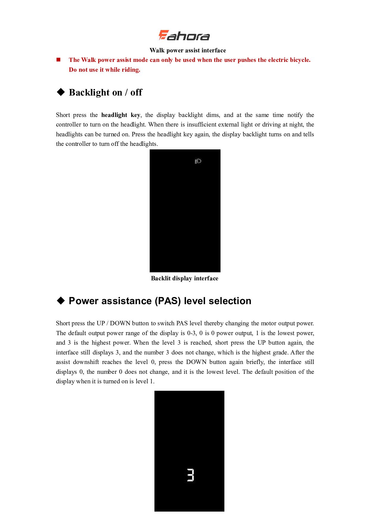
    mode can only be used when the user pushes the electric bicycle. Do not use it while riding.  Backlight on / off Short press the headlight key, the display backlight dims, and at the same time notify the controller to turn on the headlight. When there is insufficient external light or driving at night, the headlights can be turned on. Press the headlight key again, the display backlight turns on and tells the controller to turn off the headlights. Backlit display interface  Power assistance (PAS) level selection Short press the UP / DOWN button to switch PAS level thereby changing the motor output power. The default output power range of the display is 0-3, 0 is 0 power output, 1 is the lowest power, and 3 is the highest power. When the level 3 is reached, short press the UP button again, the interface still displays 3, and the number 3 does not change, which is the highest grade. After the assist downshift reaches the level 0, press the DOWN button again briefly, the interface still displays 0, the number 0 does not change, and it is the lowest level. The default position of the display when it is turned on is level 1.
  7. 9 PAS level interface  Battery bars The battery displays

    5 power bars. When the battery voltage is high, all 5 bars are on. When the battery is under voltage, the outer frame of the battery flashes at a frequency of 1HZ, prompting you to charge immediately. Battery indication interface  Motor power indication You can know the motor output power through the display. The display mode is shown in the figure below. Motor power indication interface
  8. 10  Error code indication Error code indication interface 

    When an error code appears on the display interface, remove the fault in a timely manner. The electric bike will not run normally after the fault occurs. General settings Press and hold M to power on. In the on state, when the bicycle is stationary, press and hold the UP and DOWN buttons simultaneously for more than 2 seconds, the display will enter the general setting state.  Each setting item needs to be set when the bicycle is stationary.
  9. 11  Single mileage reset TC stands for Clear Single

    Mileage. Press the UP / DOWN button to select Y / N. Y (Yes) means to clear the mileage of a single trip. N (No) means that the mileage of a single trip is not cleared. Press ‘i’ key to confirm and enter the backlight brightness setting state. Single mileage reset interface  Backlight brightness bL stands for backlight. You can set the parameters 1, 2, and 3 to indicate the backlight brightness, 1 is the darkest, 2 is the standard brightness, and 3 is the brightest. The default value of the display is 1. You can change the backlight brightness parameter by pressing the UP / DOWN button. Press the ‘i’ key to confirm and enter the metric and English unit conversion setting state. Press and hold the ‘i’ key to confirm and exit the general setting state. Backlight brightness setting interface
  10. 12  Imperial and Metric Unit Conversion U stands for

    the unit, 1 is the English system, and 2 is the metric system. The speed and mileage units can be changed by pressing the UP / DOWN button. Press the "i" key to confirm, press and hold the 'i' key to confirm and exit the normal setting state. The display's default unit is metric. Imperial and Metric Unit Conversion interface
  11. 13 General parameter settings Simultaneously press the UP + DOWN

    button for more than 2 seconds to enter the general setting state. Then press the DOWN and ‘i’ simultaneously for more than 2 seconds to enter the wheel diameter setting interface.  Wheel diameter setting LD stands for wheel diameter, and the settable values are: 8-26, 700C, 28-30. Press the UP / DOWN button to select the wheel diameter corresponding to the bicycle to ensure the accuracy of the meter speed display and mileage display. The display factory default wheel diameter value is 26 inch or 20 inch. Press ‘i’ key to enter the speed limit setting interface. Wheel diameter setting interface
  12. 14  Speed limit setting The default value of the

    maximum riding speed of the display is 25Km / h. Changing this value can set the maximum riding speed of the electric bike. When the electric power exceeds the set value, the controller will stop the power supply to the motor to protect the rider's driving safety; LS stands for speed limit. The selectable range of the maximum speed setting value is between 12Km / h and 40Km / h, which can be adjusted by the UP / DOWN button. Press and hold the ‘i’ button to confirm and exit the setting state. Speed limit setting interface Personalization settings In order to meet the customer's personalized usage requirements, personalized settings are set, which include the display's battery power settings, boost parameter settings, current limit value settings, boost sensor settings, speed sensor settings, handlebar function settings, system settings and Power-on password settings, a total of eight settings. At the same time, press and hold the UP and DOWN buttons for more than 2 seconds to enter the normal setting state; Then press and hold the UP and DOWN buttons for more than 2 seconds at the same time again to enter the display personalization item selection interface; Select the content to be set by UP / DOWN, and press ‘i’ key enters the corresponding setting interface.  Ensure you do not change Personalization settings. Changing Personalization settings may cause your bike to stop working properly. If you need the default settings for the advanced settings menu, please contact Eahora.
  13. 15 Personalized item selection interface  Battery level setting VOL

    stands for voltage, and requires 1 to 5 voltage values to be input one by one. Take the first power value as an example: "1" on the screen indicates the first voltage, and "34.5" is the first power value. Press the UP / DOWN button to increase / decrease the value, press ‘i’ key to confirm and enter the next section of power setting interface; after setting the 5 power values, press and hold ‘i’key to confirm and return to setting item selection interface of the display.
  14. 16 Battery level setting interface  Power assist parameter setting

    (optional) PAS levels selection Eight modes are provided in the PAS levels selection: 0-3, 1-3, 0-5, 1-5, 0-7, 1-7, 0-9, 1-9; by UP / DOWN and press the ‘i’ key to confirm and enter the assist ratio value setting interface in the corresponding mode. The display's default mode is 0-3. PAS levels selection interface PAS ratio value setting By setting the assist ratio value, the speed of each level can be adjusted to meet the same needs of non-cyclists. Take the level 1 as an example, “45-55%” is the range of the level 1 ratio, and “50%” is the default value of the level 1. It is a settable value. Use the UP / DOWN button to add / subtract the setting. Short press ‘i’ key to confirm and enter the next boost ratio setting, up to 9 can be set. After setting, press and hold ‘i’ key to confirm and return to the setting item selection interface of the display. Refer to Schedule 2 for details. PAS ratio value setting interface
  15. 17  Current limit value setting (optional) CUR stands for

    current limit. The current limit can be set in the range of 7.0-25.0A. Press the UP / DOWN button to change the maximum current value of the controller. Press and hold the ‘i’ key to confirm and return to the setting item selection interface of the display. The display's factory default is 15.0A. Current limit value setting interface  Booster sensor setting (optional) Direction setting of power sensor PAS stands for power sensor. Run-F / b is displayed on the screen. run-F stands for forward direction, run-b stands for reverse direction. Press the UP / DOWN button to switch. Press the ‘i’ button to confirm and enter the sensitivity setting of the booster sensor. The display's factory default value is forward. Direction setting interface of power sensor
  16. 18 Booster sensor sensitivity setting SCN stands for the sensitivity

    of the booster sensor; the setting range is 2-9, where 2 is the highest sensitivity and 9 is the lowest sensitivity; use the UP / DOWN button to add / subtract the setting, and press the ‘i’ key to confirm and enter the power sensor proportional parameter setting interface. The display's factory default value is 2. Booster sensor sensitivity setting interface Setting magnetic disk number SPS stands for speed sensor. It can be set according to the number of magnetic heads installed on the wheels of electric vehicles. The setting range is 1-15; press the UP / DOWN button to modify it, press and hold the ‘i’ button to confirm and return to the instrument setting item selection interface. The display factory default value is 1. Setting magnetic disk number interface  Throttle setting(optional) Throttle boosts enable settings
  17. 19 Hnd stands for throttle, HL for turn-assisted pushing, HL-N

    for throttle-assisted pushing, HL-Y for throttle-assisted pushing, that is, when turning the throttle, the display enters the boost-driven mode; by UP / DOWN You can switch Y / N, press the ‘i’ key to confirm, if you select N, you will enter the throttle position enable setting interface; otherwise, you will return to the display instrument setting item selection interface. The display's factory default value is N. Throttle setting interface Throttle gear enable setting HF-Y stands for throttle step, HF-N means throttle is not stepped. If throttle step is selected, it means that when turning the throttle, the maximum speed can only reach the corresponding speed corresponding to the gear position displayed on the meter. Split, it means that when turning the throttle, it is not limited by the gear on the display, and can reach the rated maximum speed. You can set Y / N by pressing the UP / DOWN button. Press the "i" key to confirm and return to the throttle to assist the implementation. Enable setting interface; long press “I” key to confirm and return to the setting item selection interface of the display. The factory default value of the meter is N. Throttle gear enable setting interface
  18. 20  System settings (optional) Battery delay time setting dLY

    stands for battery delay time. You can select the battery delay time 3/6/12s by pressing the UP / DOWN button. Press the ‘i’ button to confirm and enter the maximum speed setting interface. The display's factory default is 3s. Battery delay time setting interface Buttons help push enable settings PUS stands for push enable. Press UP / DOWN to switch Y / N. Y stands for enable and N stands for disable. Short press “i” to confirm and enter the speed setting for boost. The display's factory default is Y. Buttons help push enable settings interface Slow start settings SSP stands for slow start, and the adjustable range is 1-4, 4 stands for the slowest; it can be selected by the UP / DOWN button, press and hold “i” to confirm and exit the setting. The
  19. 21 display's factory default value is 1. Slow start settings

    interface  Power-on password setting Press the ‘i’ button to enter the password setting state, and the screen prompts "P2", indicating the power-on password. Press the ‘i’ key to shift, and use the UP / DOWN key to increase / decrease the input value. After the 4-digit password is entered, press the ‘i’ key to confirm. If the password is correct, enter the power-on password enable setting interface. Enter the status. The default power-on password is 1212. Power-on password input setting interface Power-on password enable
  20. 22 Enter the password enable interface after entering the password,

    and select Y / N with the UP / DOWN button. Y indicates that a power-on password is required, and N indicates that a power-on password is not required. Press the ‘i’ key to confirm. If Y is selected, press the ‘i’ key to enter the password modification state, otherwise exit the password setting and return to the instrument setting item selection interface. The display's factory default is N. Power-on password enable interface Power-on password modification The display shows P3. Press the ‘i’ key to shift, and use the UP / DOWN key to increase / decrease the value. After modification, press and hold ‘i’ to save and confirm, and exit the setting interface. Restarting the display will show P1, 0000. The display can work normally only after entering the correct password. Power-on password modification interface  Exit Settings In the setting state, press the ‘i’ key (within 2 seconds) to confirm the input to save the current
  21. 23 setting; press and hold the ‘i’ key (more than

    2 seconds) to confirm to save the current setting and exit the current setting state; long press the DOWN button (2 seconds or more) To cancel the current operation and exit the setting, the current setting data is not saved.  If no operation is performed within one minute, the meter automatically exits the setting state. Restore default settings dEF means restore the default parameters. Press and hold the UP + i buttons for more than 2 seconds at the same time in the normal display interface to enter the restore default parameters interface. Press the UP / DOWN button to switch Y / N. Y means the default parameters need to be restored. N means not. You need to restore the default parameters. If you select Y, press and hold the ‘i’ key for more than 2 seconds to confirm. The meter will automatically start to restore the default settings and display dEF-00. After the restoration of the defaults, the system will automatically exit and return to the normal display interface. Restore default setting interface Quality commitment and warranty Warranty Information: 1. For any failure caused by the quality of the product under normal use, the company will be responsible for giving limited warranty during the warranty period. 2. The warranty period of the product is within 12 months after the instrument leaves the factory. The following conditions are not covered by the warranty 1. The shell is opened 2.The connector is damaged
  22. 24 3. The casing of the display is scratched or

    damaged after leaving the factory. 4.The lead wire of the display is scratched or broken 5. Failure or damage caused by force majeure (such as fire, earthquake, etc.) or natural disasters (such as lightning, etc.) 6. The product is out of warranty Lead connection diagram Standard connector cable sequence Connection with the controller Meter outlet Butt terminal Table: Wire sequence table of standard connectors Standard wiring sequence Standard wiring color Features 1 Red (VCC) Display power line 2 Blue (Kp) Controller power control line 3 Black (GND) Display ground line 4 Green (RX) Display data receiving line 5 Yellow (TX) Display data transmission line  The leads of some products use waterproof connectors, and users cannot see the color of the leads in the harness. Precautions Pay attention to safety during use. Do not plug or unplug the monitor while it is powered on.  Try to avoid bumping the display.
  23. 25  Regarding the background parameter setting of the display

    instrument, please do not change it at will, otherwise normal riding cannot be guaranteed.  When the display cannot be used normally, it should be repaired as soon as possible. Schedule 1: Error code definition table Error code definition 21 Abnormal current 22 Abnormal throttle 23 Abnormal motor 24 Motor model is abnormal 25 Abnormal brake 30 Communication error Schedule 2: Table of default values for PAS level ratio