engineering and live programming. • Software visualization attempts to solve a similar problem as the one that live programming addresses - reducing programming complexity by making it easier to understand quickly what a program is doing or supposed to do. • By combining approaches from both areas we intend to provide a live visualization method that provides continuous feedback about a virtual cloud infrastructure.
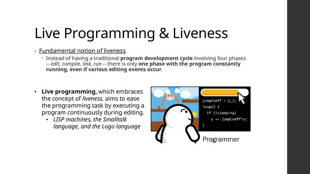
Instead of having a traditional program development cycle involving four phases -- edit, compile, link, run -- there is only one phase with the program constantly running, even if various editing events occur. • Live programming, which embraces the concept of liveness, aims to ease the programming task by executing a program continuously during editing. • LISP machines, the Smalltalk language, and the Logo language
Static Dynamic 3D-based visualizations • Several examples of visualizations: CodeCrawler: Software metric visualization from several reverse engineering tools. Jinsight: Runtime data analysis. Wettel et al. 3D representation of the architecture of software as a city. • Teyseyre et al. groups 3D representations in two: abstract visual or real- world representations.
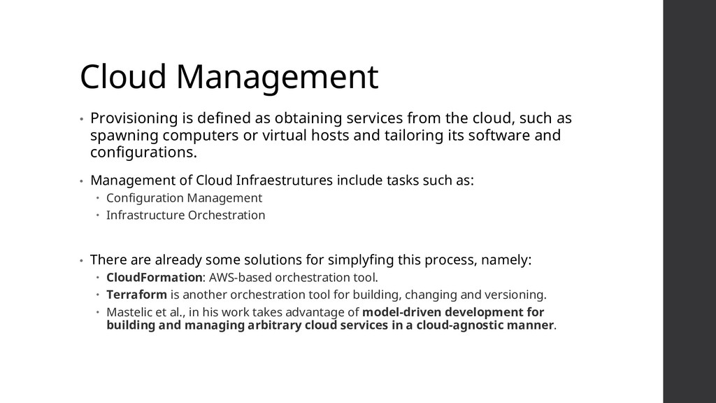
the cloud, such as spawning computers or virtual hosts and tailoring its software and configurations. • Management of Cloud Infraestrutures include tasks such as: Configuration Management Infrastructure Orchestration • There are already some solutions for simplyfing this process, namely: CloudFormation: AWS-based orchestration tool. Terraform is another orchestration tool for building, changing and versioning. Mastelic et al., in his work takes advantage of model-driven development for building and managing arbitrary cloud services in a cloud-agnostic manner.
metaphor. • The main concept is to allow the design and analysis of cloud compositions through an intuitive mapping between city metaphors and cloud resources. • Representing the cloud as a city intends to enable users to gradually become familiar with the represented architecture, due to the relationship with many similarities between the two domains. • The main difference from other model-driven approaches is that this environment doesn't reflect a static infrastructure mapping, but instead a live infrastructure which shows the real-time state of each component. A metaphor that we introduce as, the live city.
provides a set of tools: Cloud Service Providers API Connection to a specific cloud service provider. Importer Periodically pools the provider and detects changes in the infrastructure state. Resources A group of resources can either contain a resource or another resource group (Composite Pattern).
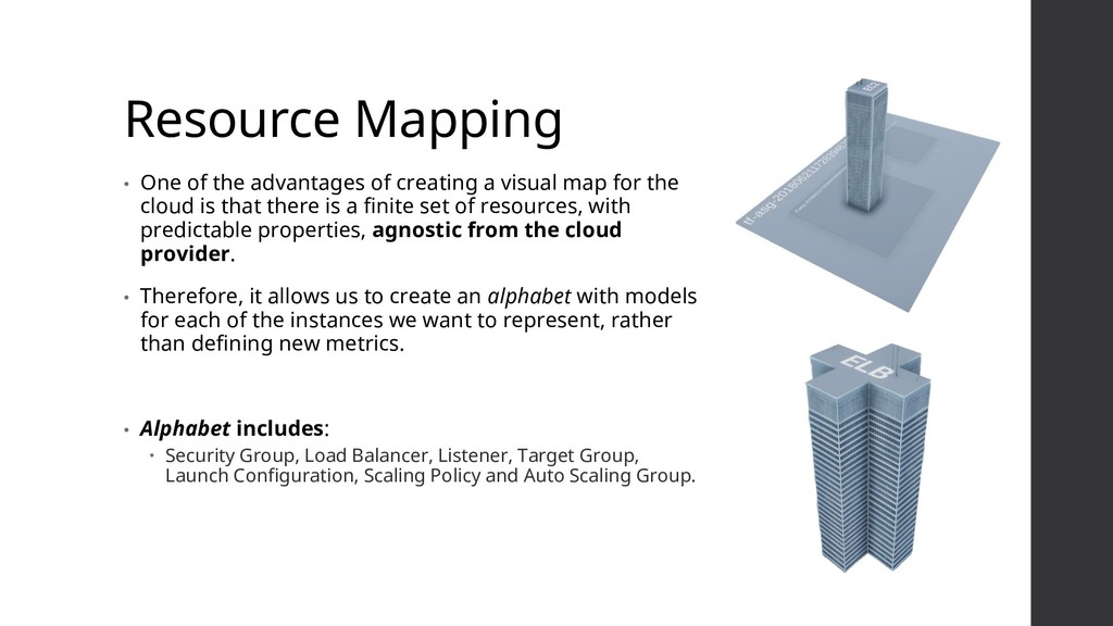
visual map for the cloud is that there is a finite set of resources, with predictable properties, agnostic from the cloud provider. • Therefore, it allows us to create an alphabet with models for each of the instances we want to represent, rather than defining new metrics. • Alphabet includes: Security Group, Load Balancer, Listener, Target Group, Launch Configuration, Scaling Policy and Auto Scaling Group.
the architecture is expanded and modified. Support for laying out all the imported components of the infrastructure, with different dimensions, in an ordered manner Do not waste much of the cities’ real- estate. Support for grouping components according to a class.
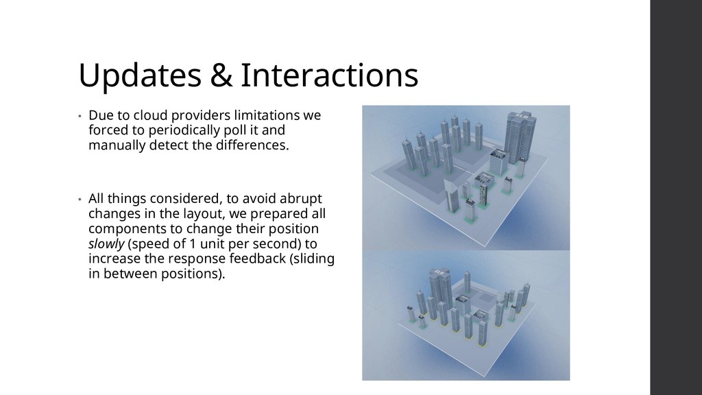
forced to periodically poll it and manually detect the differences. • All things considered, to avoid abrupt changes in the layout, we prepared all components to change their position slowly (speed of 1 unit per second) to increase the response feedback (sliding in between positions).
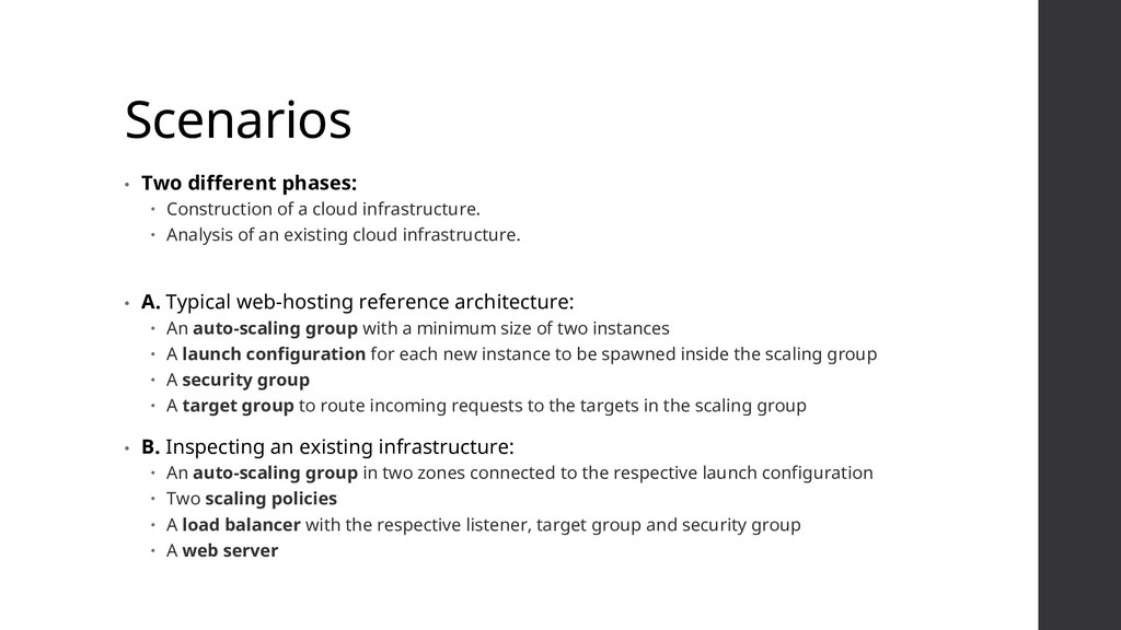
infrastructure. Analysis of an existing cloud infrastructure. • A. Typical web-hosting reference architecture: An auto-scaling group with a minimum size of two instances A launch configuration for each new instance to be spawned inside the scaling group A security group A target group to route incoming requests to the targets in the scaling group • B. Inspecting an existing infrastructure: An auto-scaling group in two zones connected to the respective launch configuration Two scaling policies A load balancer with the respective listener, target group and security group A web server
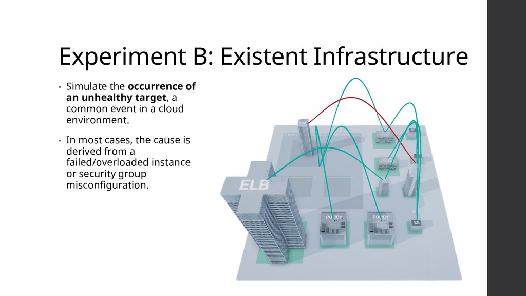
unhealthy target, a common event in a cloud environment. • In most cases, the cause is derived from a failed/overloaded instance or security group misconfiguration.
architect and configure cloud compositions with a higher level of abstraction. Enabling architects to focus their interests in specific areas, and track the changes as the infrastructure evolves and the complexity increases. • Approach combines the strengths of existing approaches, techniques and tools by introducing liveness to cloud management and providing a complete feedback loop which can help developers understand how the infrastructure reacts to change, working towards a Live Software Development.
user’s ability to manually modify the position of a specific component. 2. Explore other levels of liveness. 3. Research the use of different metaphors.