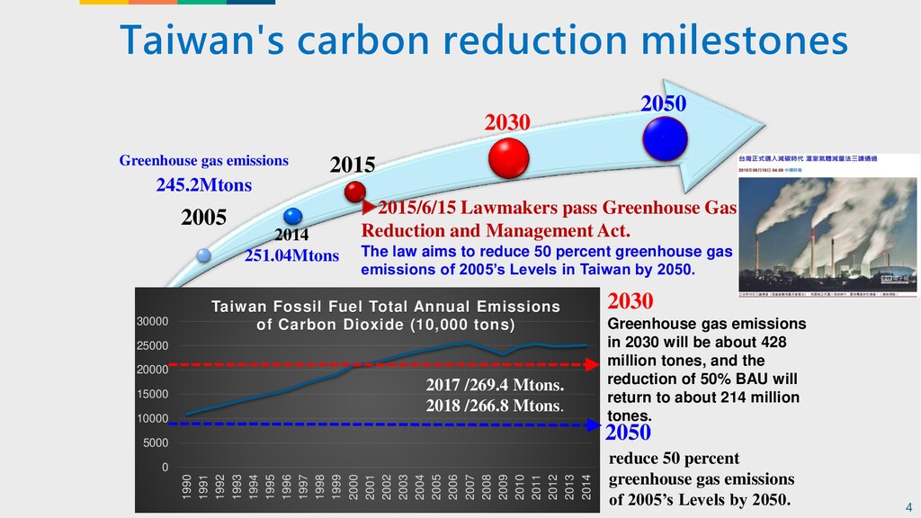
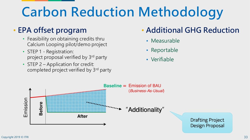
and Management Act. The law aims to reduce 50 percent greenhouse gas emissions of 2005’s Levels in Taiwan by 2050. 2050 2030 Greenhouse gas emissions in 2030 will be about 428 million tones, and the reduction of 50% BAU will return to about 214 million tones. Greenhouse gas emissions 245.2Mtons 2005 0 5000 10000 15000 20000 25000 30000 1990 1991 1992 1993 1994 1995 1996 1997 1998 1999 2000 2001 2002 2003 2004 2005 2006 2007 2008 2009 2010 2011 2012 2013 2014 Taiwan Fossil Fuel Total Annual Emissions of Carbon Dioxide (10,000 tons) 2014 251.04Mtons 2015 2030 2050 reduce 50 percent greenhouse gas emissions of 2005’s Levels by 2050. 4 2017 /269.4 Mtons. 2018 /266.8 Mtons.
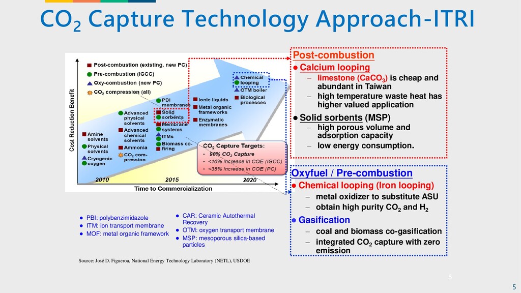
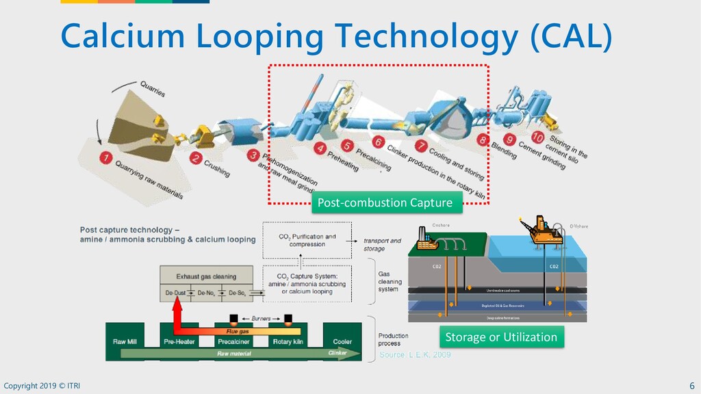
MOF: metal organic framework ⚫ CAR: Ceramic Autothermal Recovery ⚫ OTM: oxygen transport membrane ⚫ MSP: mesoporous silica-based particles Post-combustion ⚫ Calcium looping – limestone (CaCO3 ) is cheap and abundant in Taiwan – high temperature waste heat has higher valued application ⚫ Solid sorbents (MSP) – high porous volume and adsorption capacity – low energy consumption. Oxyfuel / Pre-combustion ⚫ Chemical looping (Iron looping) – metal oxidizer to substitute ASU – obtain high purity CO2 and H2 ⚫ Gasification – coal and biomass co-gasification – integrated CO2 capture with zero emission CO 2 Capture Technology Approach-ITRI Source: José D. Figueroa, National Energy Technology Laboratory (NETL), USDOE 5
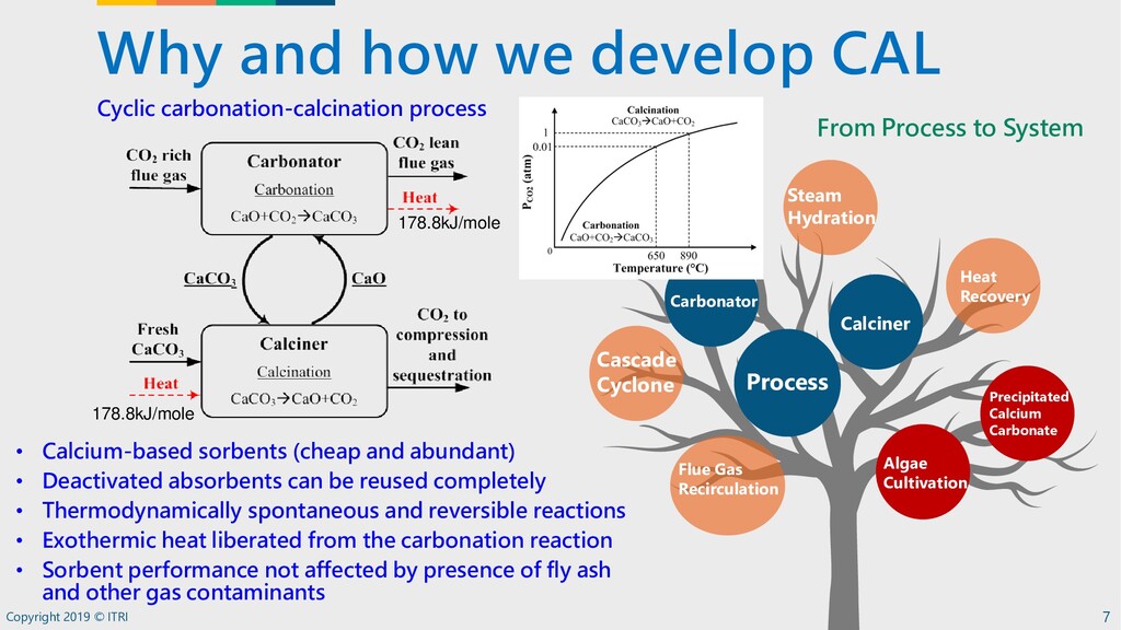
7 Heat Recovery Process Calciner Cascade Cyclone Precipitated Calcium Carbonate Carbonator Flue Gas Recirculation Steam Hydration From Process to System 178.8kJ/mole 178.8kJ/mole • Calcium-based sorbents (cheap and abundant) • Deactivated absorbents can be reused completely • Thermodynamically spontaneous and reversible reactions • Exothermic heat liberated from the carbonation reaction • Sorbent performance not affected by presence of fly ash and other gas contaminants Cyclic carbonation-calcination process Algae Cultivation
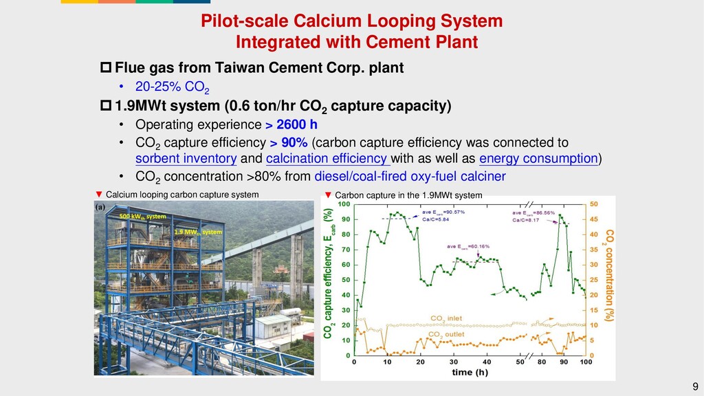
gas from Taiwan Cement Corp. plant • 20-25% CO2 1.9MWt system (0.6 ton/hr CO2 capture capacity) • Operating experience > 2600 h • CO2 capture efficiency > 90% (carbon capture efficiency was connected to sorbent inventory and calcination efficiency with as well as energy consumption) • CO2 concentration >80% from diesel/coal-fired oxy-fuel calciner 9 ▼ Calcium looping carbon capture system ▼ Carbon capture in the 1.9MWt system
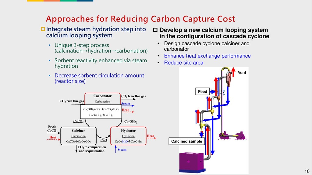
into calcium looping system • Unique 3-step process (calcination→hydration→carbonation) • Sorbent reactivity enhanced via steam hydration • Decrease sorbent circulation amount (reactor size) 10 Develop a new calcium looping system in the configuration of cascade cyclone • Design cascade cyclone calciner and carbonator • Enhance heat exchange performance • Reduce site area Vent Feed Calcined sample Carbonator Carbonation Ca(OH)2 àCaO+H2 O CaO+CO2 àCaCO3 Calciner Calcination CaCO3 àCaO+CO2 CO2 rich flue gas CO2 lean flue gas Heat Fresh CaCO3 CO2 to compression and sequestration CaCO3 CaO Heat Hydrator Hydration CaO+H2 OàCa(OH)2 Ca(OH)2 Heat Steam Steam Ca(OH)2 +CO2 àCaCO3 +H2 O CaO+CO2 àCaCO3
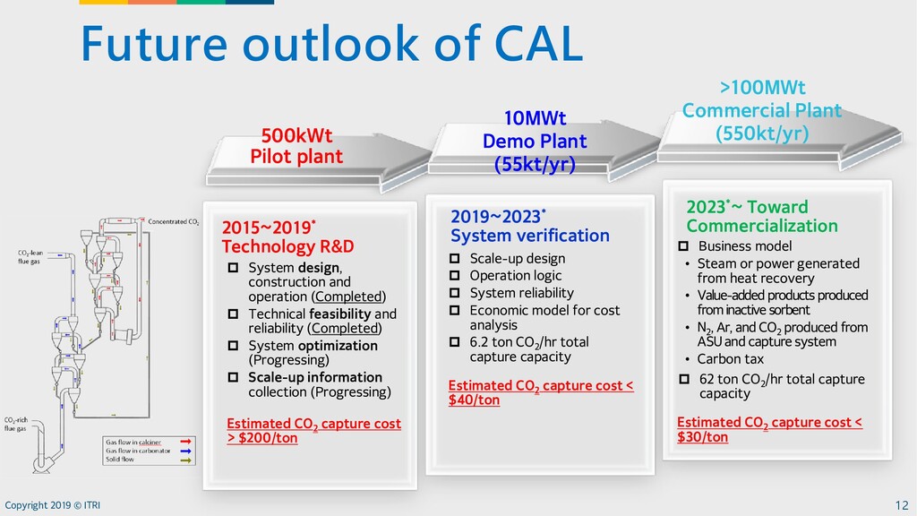
Demo Plant (55kt/yr) System design, construction and operation (Completed) Technical feasibility and reliability (Completed) System optimization (Progressing) Scale-up information collection (Progressing) Estimated CO 2 capture cost > $200/ton 2015~2019* Technology R&D Scale-up design Operation logic System reliability Economic model for cost analysis 6.2 ton CO 2 /hr total capture capacity Estimated CO 2 capture cost < $40/ton 2019~2023* System verification Business model • Steam or power generated from heat recovery • Value-added products produced from inactive sorbent • N 2 , Ar, and CO 2 produced from ASU and capture system • Carbon tax 62 ton CO 2 /hr total capture capacity Estimated CO 2 capture cost < $30/ton 2023*~ Toward Commercialization 500kWt Pilot plant >100MWt Commercial Plant (550kt/yr)
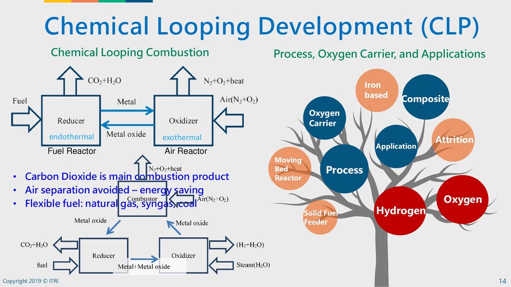
Bed Reactor Process Application Attrition Composite Oxygen Carrier Solid Fuel Feeder Hydrogen Iron based Process, Oxygen Carrier, and Applications Chemical Looping Combustion Fuel Reactor Air Reactor endothermal exothermal • Carbon Dioxide is main combustion product • Air separation avoided – energy saving • Flexible fuel: natural gas, syngas, coal Oxygen
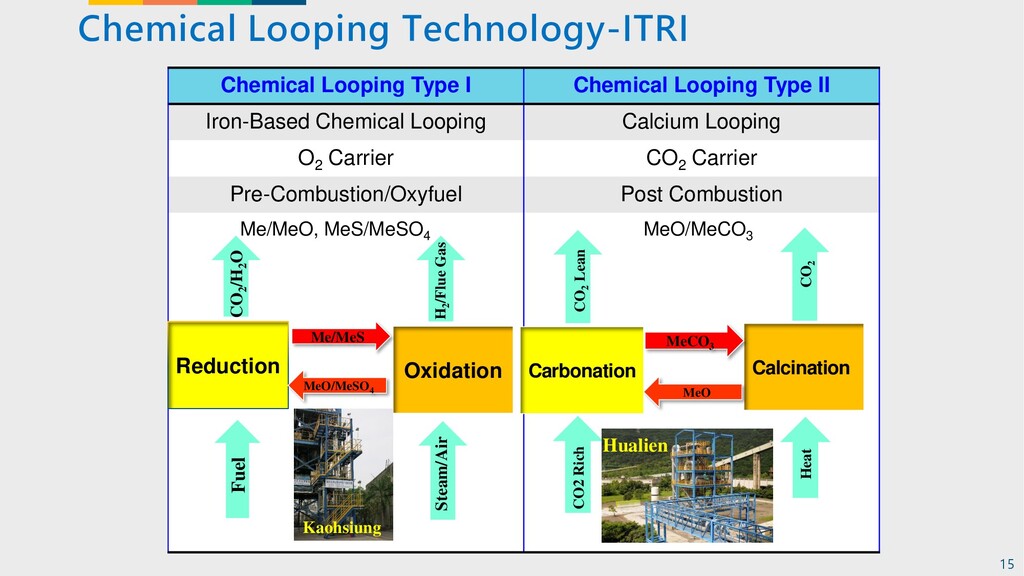
II Iron-Based Chemical Looping Calcium Looping O2 Carrier CO2 Carrier Pre-Combustion/Oxyfuel Post Combustion Me/MeO, MeS/MeSO4 MeO/MeCO3 Reduction Fuel CO2 /H2 O Oxidation Me/MeS MeO/MeSO4 Steam/Air H2 /Flue Gas Carbonation Calcination MeCO3 MeO CO2 Rich Heat CO2 Lean CO2 Kaohsiung Hualien 15
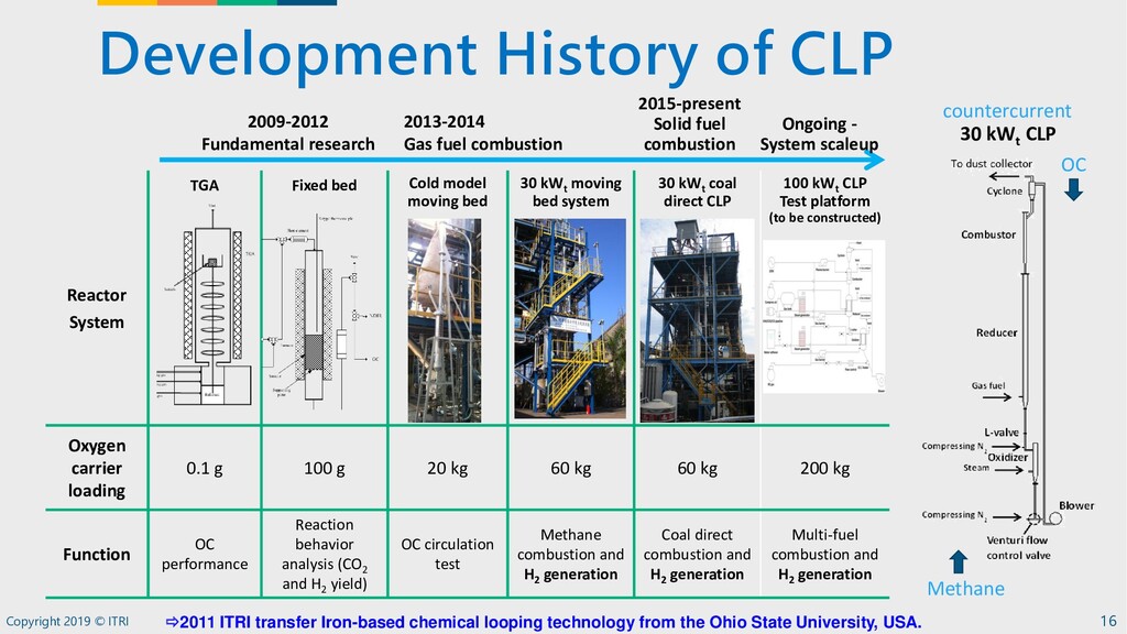
System TGA Fixed bed Cold model moving bed 30 kWt moving bed system 30 kWt coal direct CLP 100 kWt CLP Test platform (to be constructed) Oxygen carrier loading 0.1 g 100 g 20 kg 60 kg 60 kg 200 kg Function OC performance Reaction behavior analysis (CO2 and H2 yield) OC circulation test Methane combustion and H2 generation Coal direct combustion and H2 generation Multi-fuel combustion and H2 generation 2009-2012 Fundamental research 2013-2014 Gas fuel combustion 2015-present Solid fuel combustion Ongoing - System scaleup 30 kWt CLP countercurrent OC Methane 2011 ITRI transfer Iron-based chemical looping technology from the Ohio State University, USA.
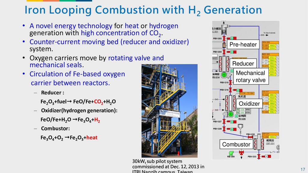
energy technology for heat or hydrogen generation with high concentration of CO2 . • Counter-current moving bed (reducer and oxidizer) system. • Oxygen carriers move by rotating valve and mechanical seals. • Circulation of Fe-based oxygen carrier between reactors. – Reducer : Fe2 O3 +fuel FeO/Fe+CO2 +H2 O – Oxidizer(hydrogen generation): FeO/Fe+H2 O Fe3 O4 +H2 – Combustor: Fe3 O4 +O2 Fe2 O3 +heat Pre-heater Reducer Mechanical rotary valve Oxidizer Combustor 30kW t sub pilot system commissioned at Dec. 12, 2013 in 17
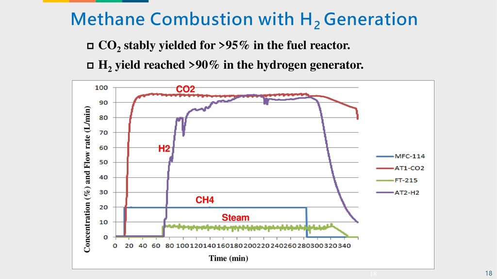
for >95% in the fuel reactor. H2 yield reached >90% in the hydrogen generator. 18 Time (min) Concentration (%) and Flow rate (L/min) H2 CO2 Steam CH4 18
fuel dual system 2.Non-mechanical valve-L valve 3.Oxygen carrier preheating device for the top for scale-up 100kWt Pilot Plant Based on 30kWt SCL Design Reducer L- valve Oxidizer Combustor 19
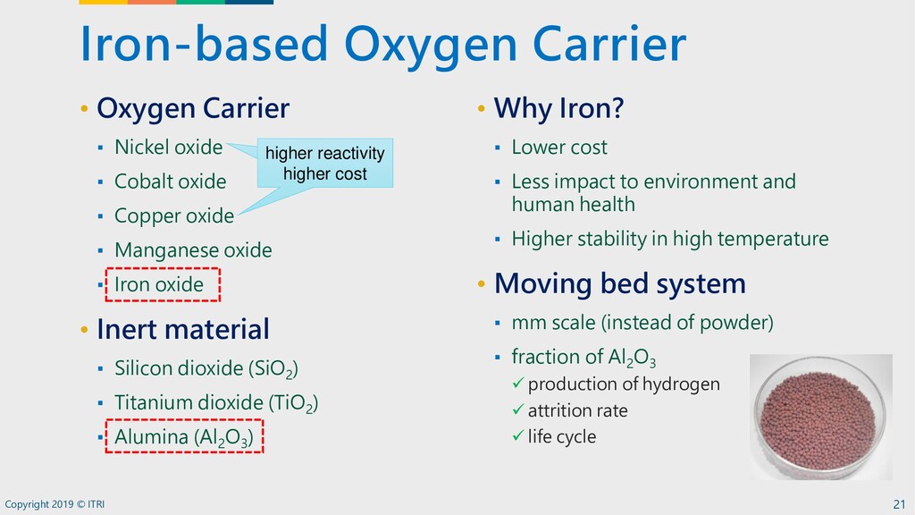
[2] STA 449F3 File Fresh_s1300_r900_10cycle_20min-syngas_10min-Air_2014.5.3.ngb-ss3 Reacted_s1300_r900_10cycle_20min-syngas_10min-Air_2014.5.ngb-ss3 Date 2014-05-30 2014-05-31 Identity Fresh Reacted Sample Fresh Reacted Mass/mg 139.660 140.823 Segment 1-42/42 1-42/42 Range 40.... 900/0.0....30.0K/min 40.... 900/0.0....30.0K/min Atmosphere N2 / N2/O2 / N2 N2 / N2/O2 / N2 Corr. --- --- 0 50 100 150 200 250 300 350 400 Time /min 86 88 90 92 94 96 98 100 TG /% Main 2014-06-11 15:55 User: Crash [1] Fresh_s1300_r900_10cycle_20min-syngas_10min-Air_2014.5.3.ngb-ss3 TG [2] Reacted_s1300_r900_10cycle_20min-syngas_10min-Air_2014.5.ngb-ss3 TG [1] [2] • 2013 ITRI transfer Iron-based oxygen carrier license agreement from National Taiwan University of Science and Technology. • Grain Fe-based oxygen carrier in 2-3 mm diameter by pelletizing and rolling methods for moving bed system • Select cost-effective oxygen carrier based on reasonable attrition rate, crush strength and reaction performance Redox performance of OC Pelletizing Rolling Development of Fe-based Oxygen Carrier Green line is fresh oxygen carrier, red line are sampling from 30 kWt SCL Sub-Pilot of the oxygen carrier. 22
23 Combined Heat and Power • Scale-up pilot • High performance and low cost composite oxygen carrier Industrial-scale Hydrogen Production • Target: competitive with existing market provider Oxygen Production • Oxygen carrier development • Integration with CAL • CLP System ✓ Gaseous fuel: 50 hrs cont. test ✓ Solid fuel: 8 hrs cont. test ✓ High concentration of CO 2 and H 2 • Oxygen Carrier ✓ Conversion rate> 65% ✓ Attrition rate < 1% w.t./cycle Common Technology Validation Platform
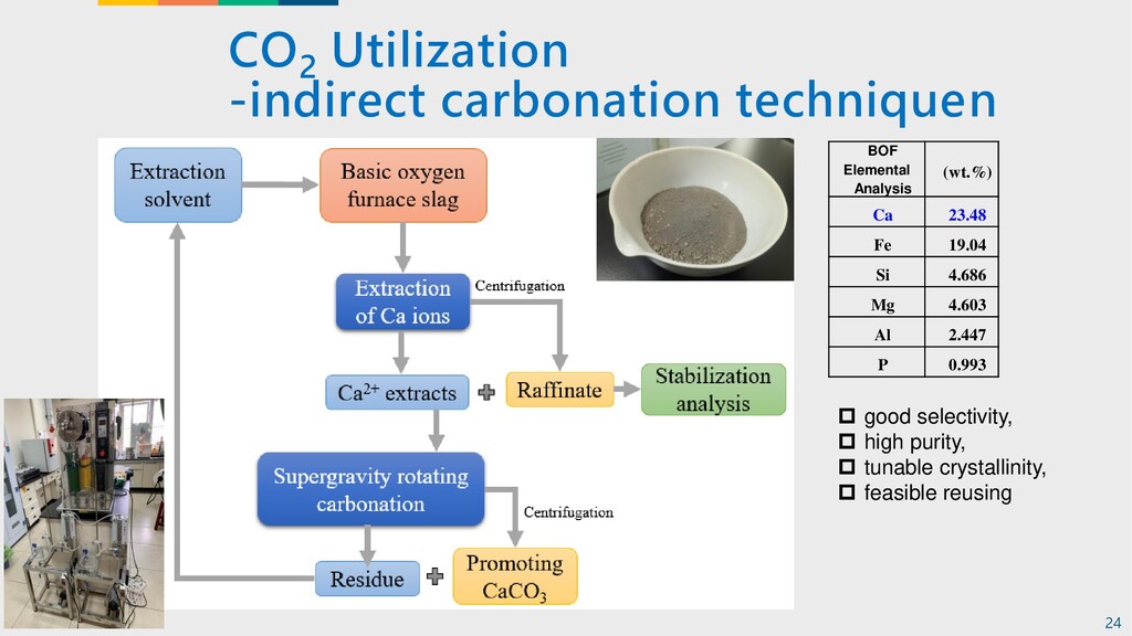
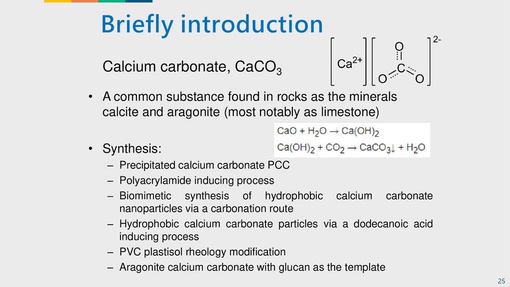
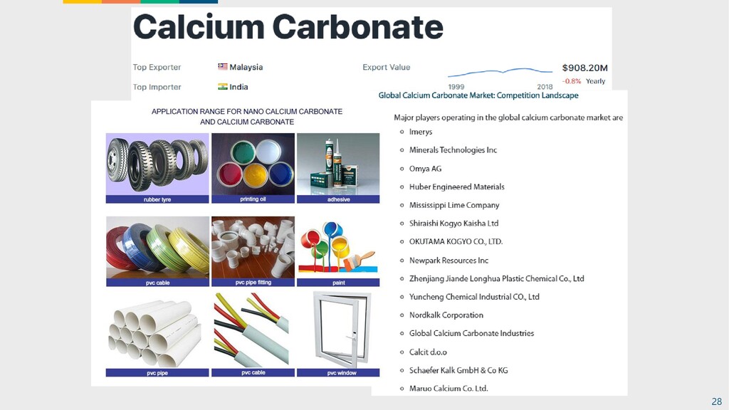
the minerals calcite and aragonite (most notably as limestone) • Synthesis: – Precipitated calcium carbonate PCC – Polyacrylamide inducing process – Biomimetic synthesis of hydrophobic calcium carbonate nanoparticles via a carbonation route – Hydrophobic calcium carbonate particles via a dodecanoic acid inducing process – PVC plastisol rheology modification – Aragonite calcium carbonate with glucan as the template Calcium carbonate, CaCO3 25
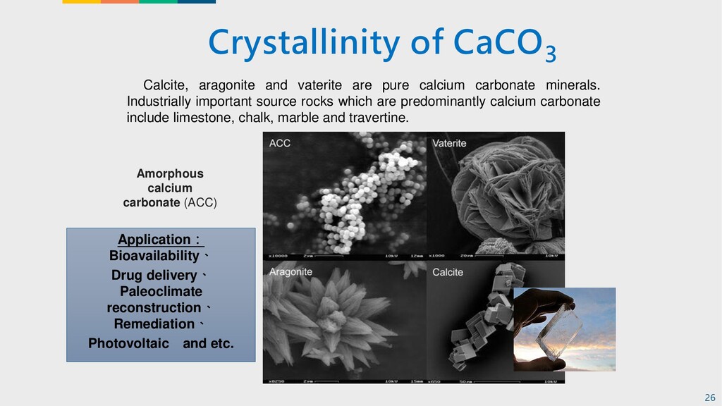
Drug delivery、 Paleoclimate reconstruction、 Remediation、 Photovoltaic and etc. Calcite, aragonite and vaterite are pure calcium carbonate minerals. Industrially important source rocks which are predominantly calcium carbonate include limestone, chalk, marble and travertine. 26
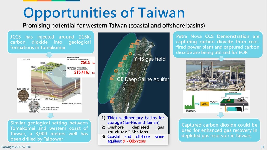
injected around 215kt carbon dioxide into geological formations in Tomakomai Similar geological setting between Tomakomai and western coast of Taiwan, a 3,000 meters well has been drilled by Taipower Petra Nova CCS Demonstration are capturing carbon dioxide from coal- fired power plant and captured carbon dioxide are being utilized for EOR Captured carbon dioxide could be used for enhanced gas recovery in depleted gas reservoir in Taiwan, Promising potential for western Taiwan (coastal and offshore basins) 1) Thick sedimentary basins for storage (Tai-His and Tainan) 2) Onshore depleted gas structures: 2.8bn tons 3) Coastal and offshore saline aquifers: 9~68bntons YHS gas field CB Deep Saline Aquifer
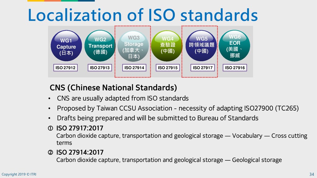
ISO 27917:2017 Carbon dioxide capture, transportation and geological storage — Vocabulary — Cross cutting terms ISO 27914:2017 Carbon dioxide capture, transportation and geological storage — Geological storage WG1 Capture (日本) WG2 Transport (德國) WG3 Storage (加拿大、 日本) WG4 查驗證 (中國) WG5 跨領域議題 (中國) WG6 EOR (美國、 挪威 ISO 27912 ISO 27913 ISO 27914 ISO 27915 ISO 27916 ISO 27917 CNS (Chinese National Standards) • CNS are usually adapted from ISO standards • Proposed by Taiwan CCSU Association - necessity of adapting ISO27900 (TC265) • Drafts being prepared and will be submitted to Bureau of Standards
![Created with NETZSCH Proteus software [#] Instrument [1] STA 449F3](https://files.speakerdeck.com/presentations/02eb6454b6674199897e6b97490b649a/slide_21.jpg)