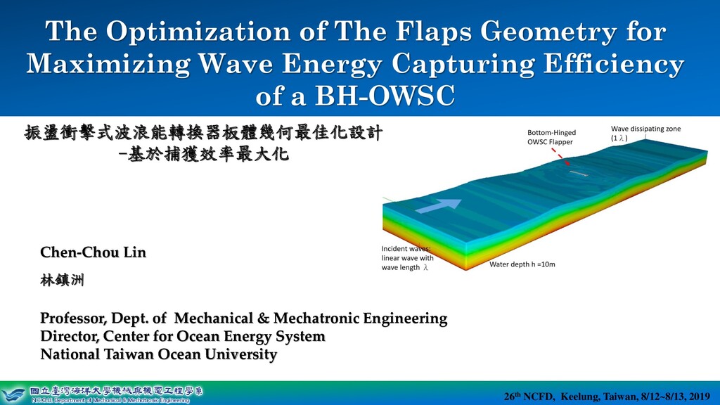
System 26th NCFD, Keelung, Taiwan, 8/12~8/13, 2019 Center for Ocean Energy System Chen-Chou Lin 林鎮洲 Professor, Dept. of Mechanical & Mechatronic Engineering Director, Center for Ocean Energy System National Taiwan Ocean University The Optimization of The Flaps Geometry for Maximizing Wave Energy Capturing Efficiency of a BH-OWSC 26th NCFD, Keelung, Taiwan, 8/12~8/13, 2019 振盪衝擊式波浪能轉換器板體幾何最佳化設計 -基於捕獲效率最大化
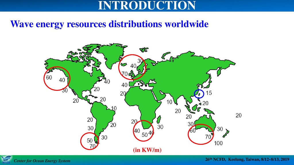
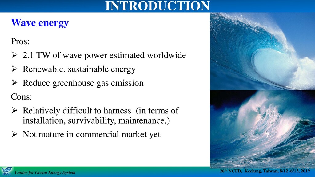
System 26th NCFD, Keelung, Taiwan, 8/12~8/13, 2019 Center for Ocean Energy System Wave energy INTRODUCTION Pros: ➢ 2.1 TW of wave power estimated worldwide ➢ Renewable, sustainable energy ➢ Reduce greenhouse gas emission Cons: ➢ Relatively difficult to harness (in terms of installation, survivability, maintenance.) ➢ Not mature in commercial market yet
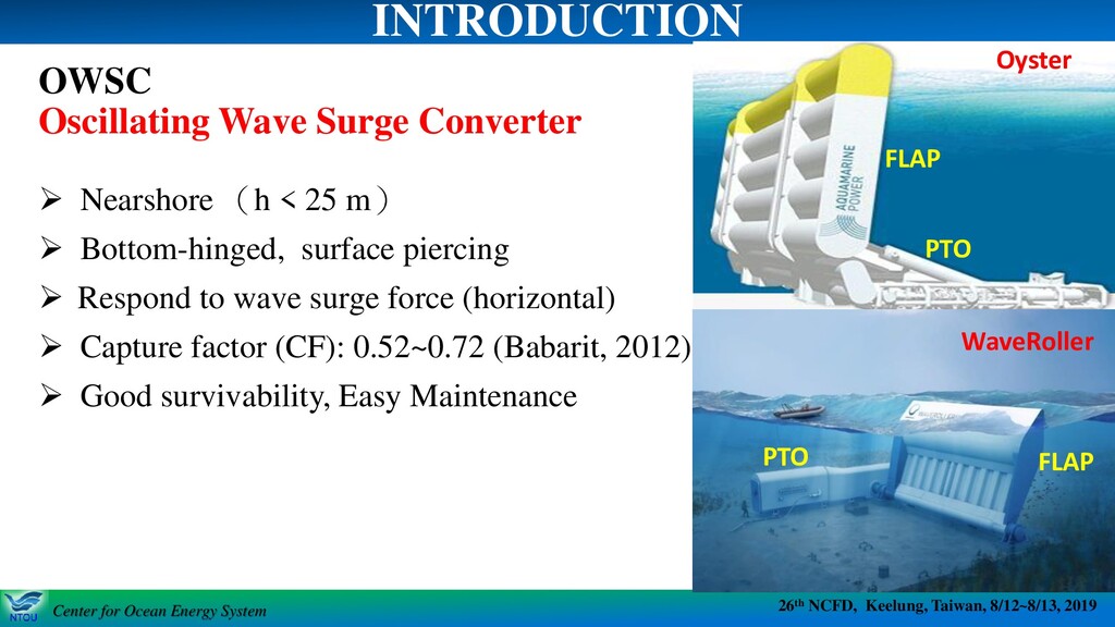
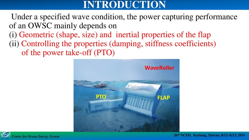
System 26th NCFD, Keelung, Taiwan, 8/12~8/13, 2019 Center for Ocean Energy System Under a specified wave condition, the power capturing performance of an OWSC mainly depends on (i) Geometric (shape, size) and inertial properties of the flap (ii) Controlling the properties (damping, stiffness coefficients) of the power take-off (PTO) INTRODUCTION WaveRoller FLAP PTO
System 26th NCFD, Keelung, Taiwan, 8/12~8/13, 2019 Center for Ocean Energy System INTRODUCTION ➢ Renzi et al. [7] used the Genetic Algorithm (GA) to optimize the flap width (10 m~30 m), hinge height (0~7.5 m) and water depth (10 m~15 m) at the installation site of the Oyster, and successfully reduced the 750,000 cases originally needed to be computed to only a few tens of cases. ➢ Anderlini et al. [8] applied ANN to maximize the power absorption for the reactive control of wave energy converters. ➢ Lin et al. [12] applied FLOW-3D (RANS-based) and WEC-Sim+WAMIT (Panel method based) to find the most influential parameter of a rectangular (box) shaped OWSC from 64 cases. It showed the flap thickness and width is the most influential dimension of the flap.
System 26th NCFD, Keelung, Taiwan, 8/12~8/13, 2019 Center for Ocean Energy System ➢It is time-consuming and computationally cost-ineffective by using CFD to design the optimal geometry of the flap. ➢The Artificial Neural Network (ANN) has the ability to train the optimization processor for better predicting the objective function (i.e. the capture factor of the OWSC) based on limited numerical (from CFD) or experimental sample results and thereby saves the computational resources. Motivation
System 26th NCFD, Keelung, Taiwan, 8/12~8/13, 2019 Center for Ocean Energy System Optimizing the flap geometry (shape and size) of the OWSC to achieve its maximal power capturing ability, or the maximal capture factor by using the ANN process. In this study, the ANN’s training data was obtained from the CFD numerical simulation results. Research Goal
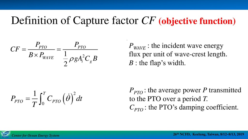
System 26th NCFD, Keelung, Taiwan, 8/12~8/13, 2019 Center for Ocean Energy System Definition of Capture factor CF (objective function) 2 1 2 PTO PTO WAVE i g P P CF B P gA C B = = ( )2 0 1 T PTO PTO P C dt T = PPTO : the average power P transmitted to the PTO over a period T. CPTO : the PTO’s damping coefficient. i P PWAVE : the incident wave energy flux per unit of wave-crest length. B : the flap’s width.
System 26th NCFD, Keelung, Taiwan, 8/12~8/13, 2019 Center for Ocean Energy System FLOW-3D: A RANS-based commercial CFD software package NNtools of MATLAB: neural network toolbox of MATLAB All CFD simulations and ANN data training and predictions were carried out on two high performance PCs, Intel core [email protected] 4 cores CPU, 128 GB RAM. Numerical tools
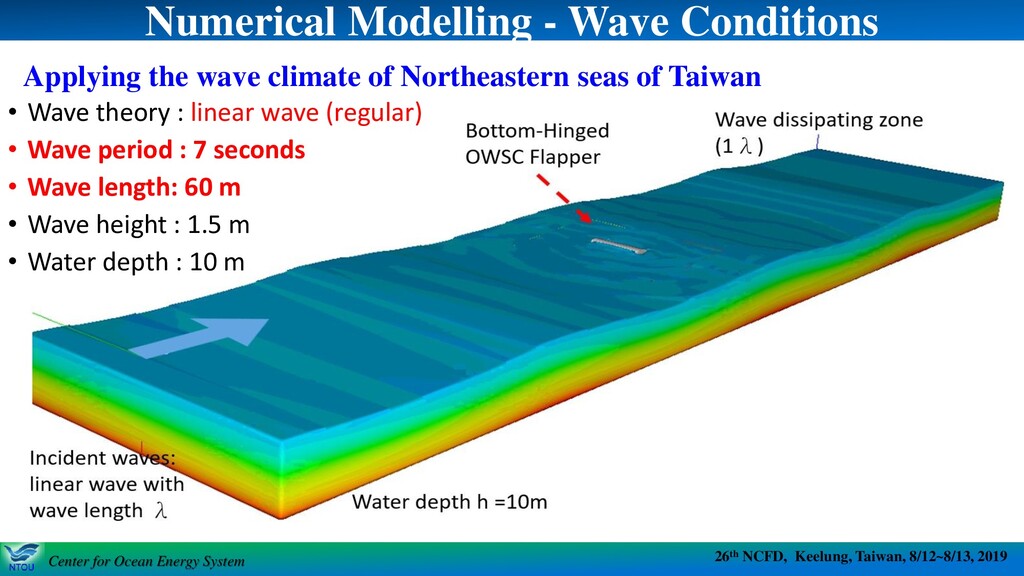
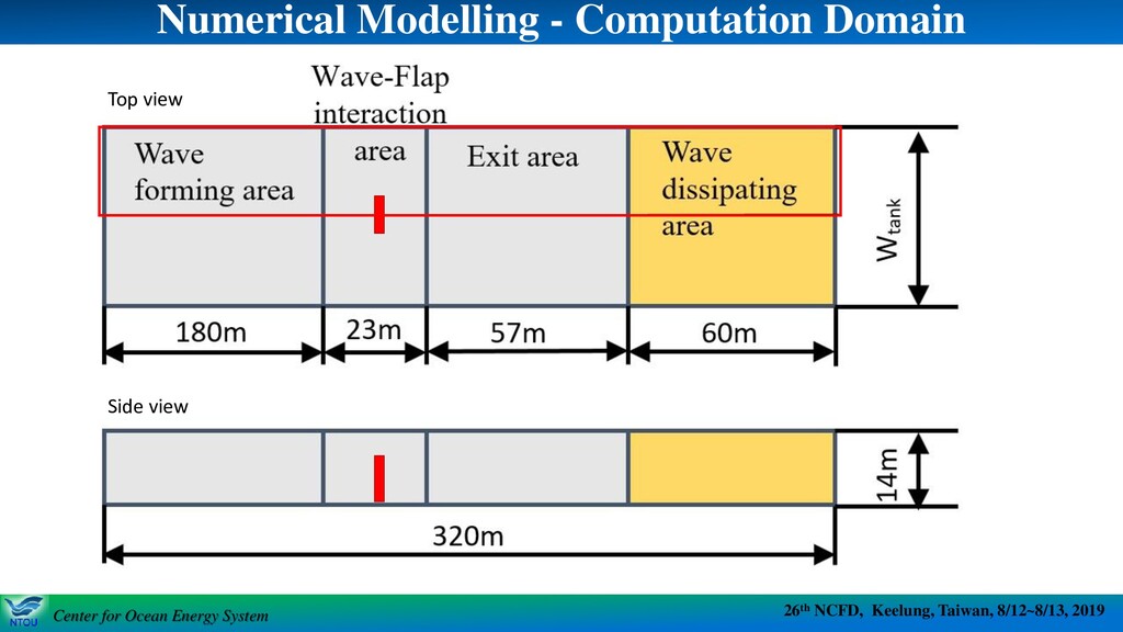
System 26th NCFD, Keelung, Taiwan, 8/12~8/13, 2019 Center for Ocean Energy System Numerical Modelling - Wave Conditions • Wave theory : linear wave (regular) • Wave period : 7 seconds • Wave length: 60 m • Wave height : 1.5 m • Water depth : 10 m Applying the wave climate of Northeastern seas of Taiwan
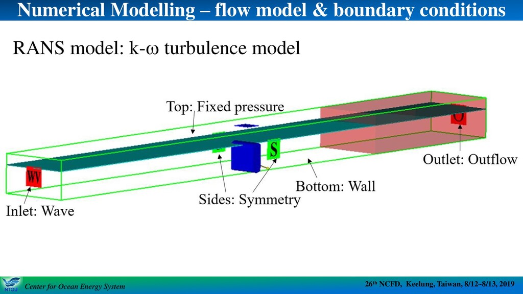
System 26th NCFD, Keelung, Taiwan, 8/12~8/13, 2019 Center for Ocean Energy System Numerical Modelling – flow model & boundary conditions RANS model: k-w turbulence model
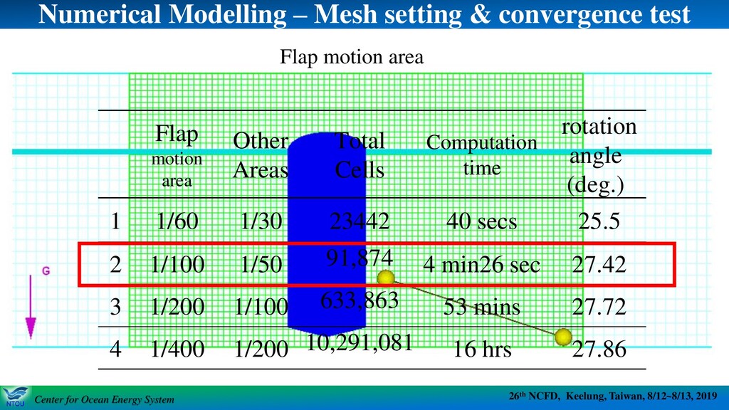
System 26th NCFD, Keelung, Taiwan, 8/12~8/13, 2019 Center for Ocean Energy System Numerical Modelling – Mesh setting & convergence test Flap motion area Other Areas Total Cells Computation time rotation angle (deg.) 1 1/60 1/30 23442 40 secs 25.5 2 1/100 1/50 91,874 4 min26 sec 27.42 3 1/200 1/100 633,863 53 mins 27.72 4 1/400 1/200 10,291,081 16 hrs 27.86 Flap motion area
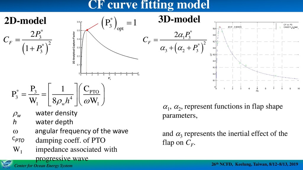
System 26th NCFD, Keelung, Taiwan, 8/12~8/13, 2019 Center for Ocean Energy System CF curve fitting model w water density h water depth w angular frequency of the wave damping coeff. of PTO W1 impedance associated with progressive wave a1 , a2 , represent functions in flap shape parameters, and a3 represents the inertial effect of the flap on CF . ( ) * 3 2 * 3 2 1 F P C P = + * 3 PTO 3 4 1 1 P C 1 P W 8 W w h w = = ( ) * 3 opt P 1 = 2D-model 3D-model ( ) * 1 3 2 * 3 2 3 2 F P C P a a a = + + CPTO
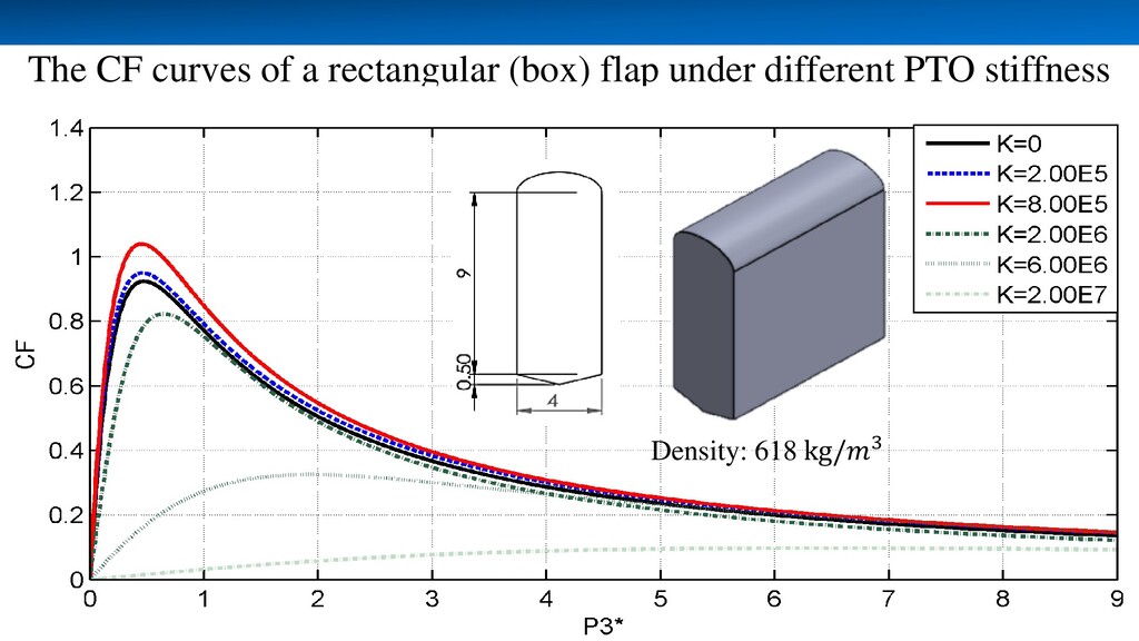
System 26th NCFD, Keelung, Taiwan, 8/12~8/13, 2019 Center for Ocean Energy System The CF curves of a rectangular (box) flap under different PTO stiffness Density: 618 kg/3
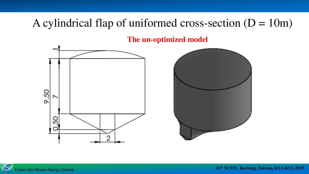
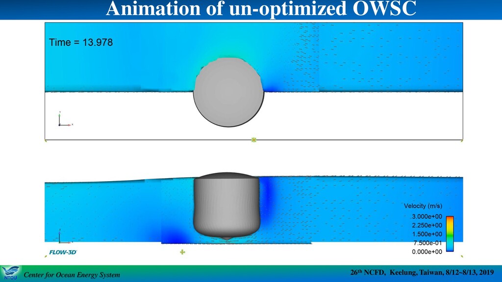
System 26th NCFD, Keelung, Taiwan, 8/12~8/13, 2019 Center for Ocean Energy System A cylindrical flap of uniformed cross-section (D = 10m) The un-optimized model
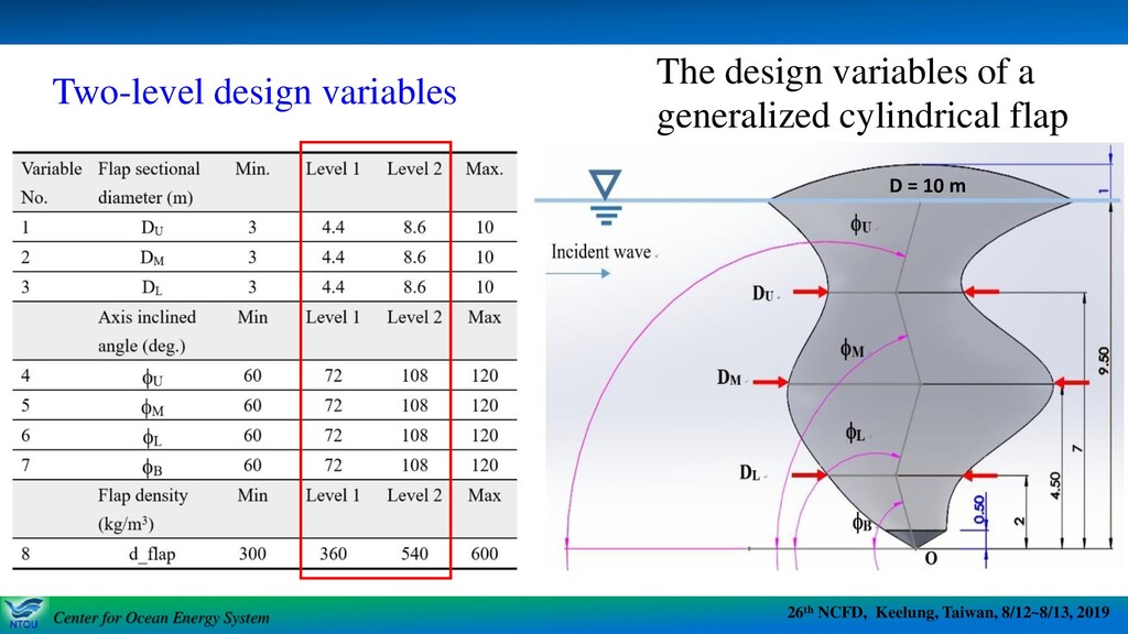
System 26th NCFD, Keelung, Taiwan, 8/12~8/13, 2019 Center for Ocean Energy System Two-level design variables The design variables of a generalized cylindrical flap D = 10 m
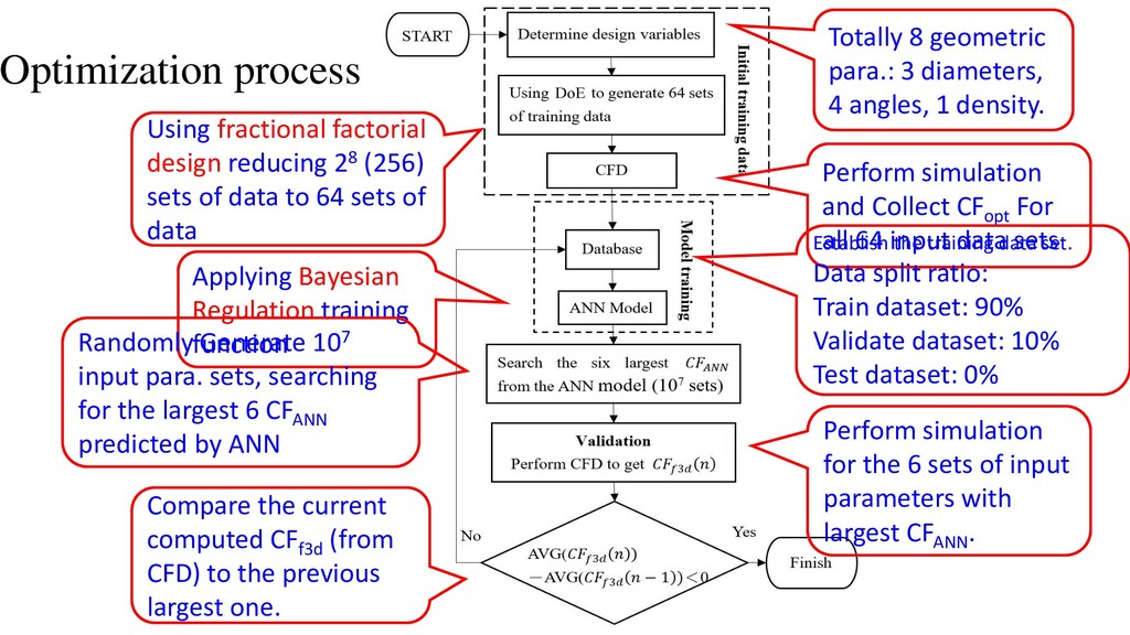
of data to 64 sets of data Totally 8 geometric para.: 3 diameters, 4 angles, 1 density. Perform simulation and Collect CFopt For all 64 input data sets Establish the training data set. Data split ratio: Train dataset: 90% Validate dataset: 10% Test dataset: 0% Applying Bayesian Regulation training function Randomly Generate 107 input para. sets, searching for the largest 6 CFANN predicted by ANN Perform simulation for the 6 sets of input parameters with largest CFANN . Compare the current computed CFf3d (from CFD) to the previous largest one.
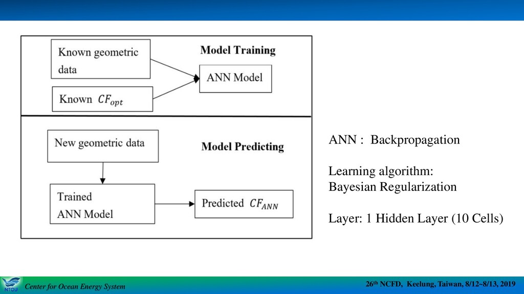
System 26th NCFD, Keelung, Taiwan, 8/12~8/13, 2019 Center for Ocean Energy System ANN : Backpropagation Learning algorithm: Bayesian Regularization Layer: 1 Hidden Layer (10 Cells)
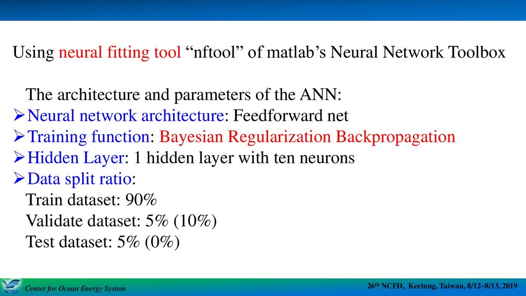
System 26th NCFD, Keelung, Taiwan, 8/12~8/13, 2019 Center for Ocean Energy System The architecture and parameters of the ANN: ➢Neural network architecture: Feedforward net ➢Training function: Bayesian Regularization Backpropagation ➢Hidden Layer: 1 hidden layer with ten neurons ➢Data split ratio: Train dataset: 90% Validate dataset: 5% (10%) Test dataset: 5% (0%) Using neural fitting tool “nftool” of matlab’s Neural Network Toolbox
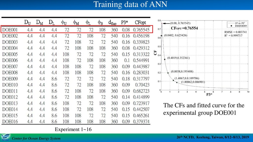
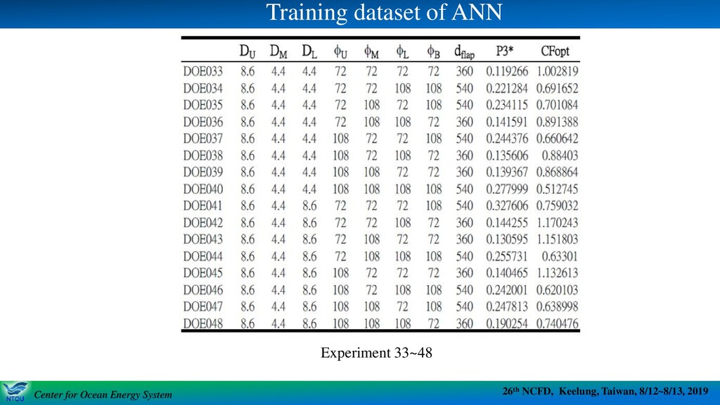
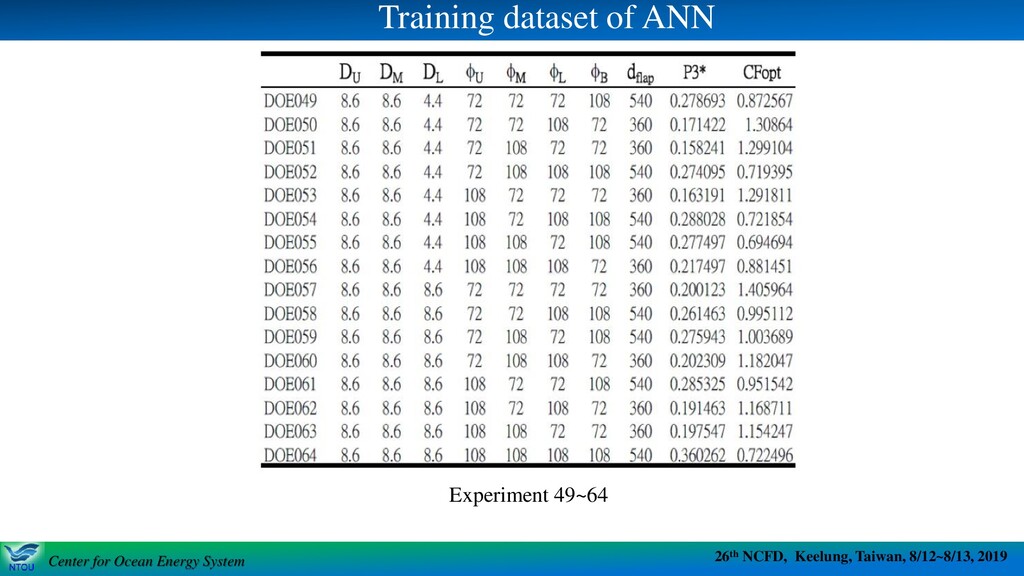
System 26th NCFD, Keelung, Taiwan, 8/12~8/13, 2019 Center for Ocean Energy System Training data of ANN The CFs and fitted curve for the experimental group DOE001 Experiment 1~16
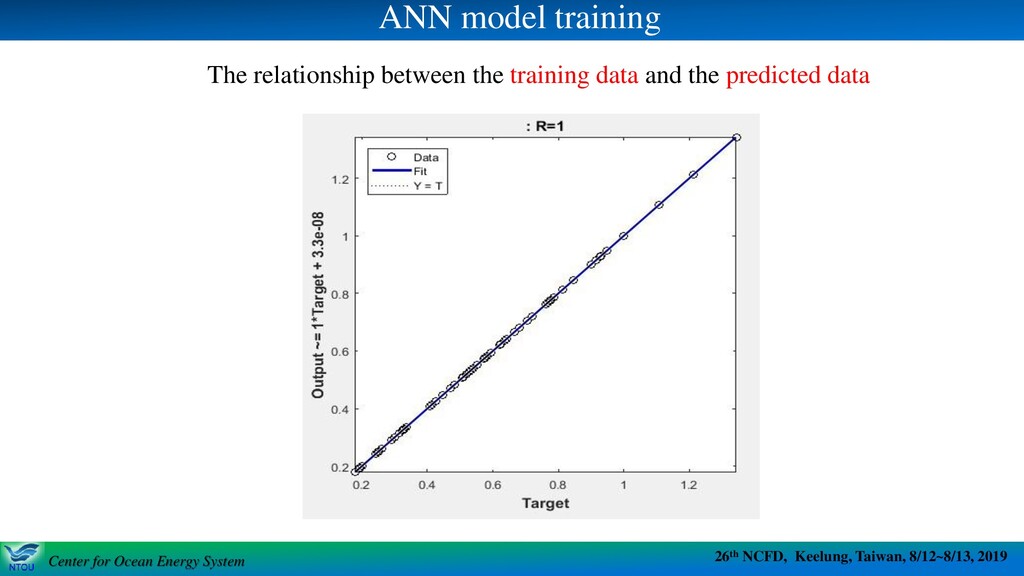
System 26th NCFD, Keelung, Taiwan, 8/12~8/13, 2019 Center for Ocean Energy System ANN model training The relationship between the training data and the predicted data
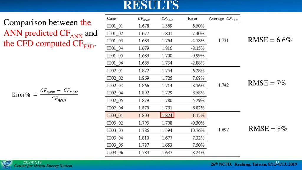
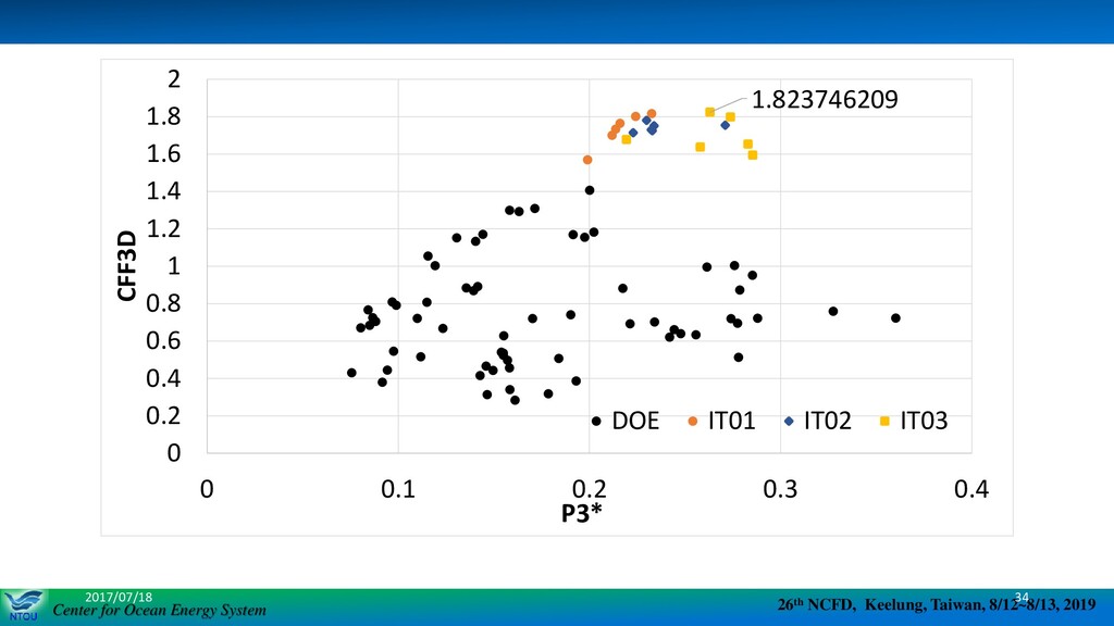
System 26th NCFD, Keelung, Taiwan, 8/12~8/13, 2019 Center for Ocean Energy System 2017/07/18 33 RESULTS Error% = − 3 RMSE = 6.6% RMSE = 7% RMSE = 8% Comparison between the ANN predicted CFANN and the CFD computed CFF3D .
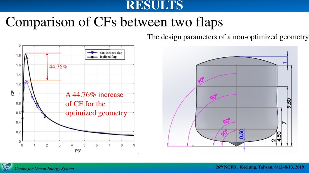
System 26th NCFD, Keelung, Taiwan, 8/12~8/13, 2019 Center for Ocean Energy System Comparison of CFs between two flaps The design parameters of a non-optimized geometry RESULTS A 44.76% increase of CF for the optimized geometry 44.76%
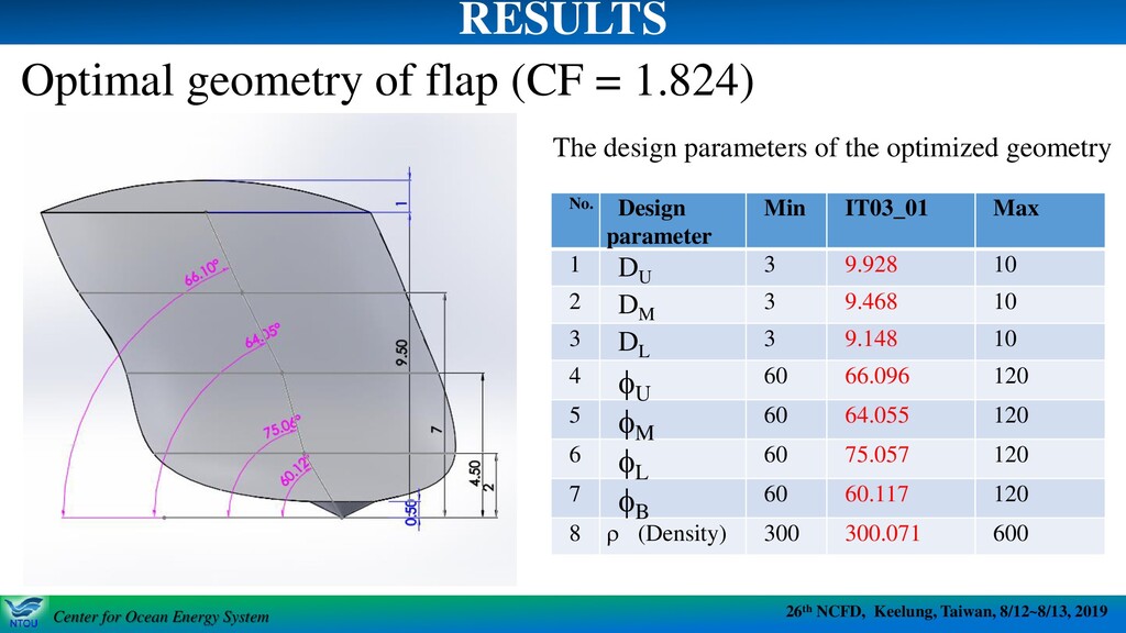
System 26th NCFD, Keelung, Taiwan, 8/12~8/13, 2019 Center for Ocean Energy System •The computational cost has been significantly reduced by applying supervised machine learning scheme, ANN-based optimization approach. •A maximal capture factor, CFF3D , of 1.824 is obtained. •The CFopt is improved by as much as 44.76% when the flap geometry is designed by ANN process (with inclined axes). •The cylinder axis of the flap inclines to the opposite direction of the incident wave propagation. •The smaller flap density the better power capturing performance of the WEC. CONCLUSIONS