Upgrade to Pro — share decks privately, control downloads, hide ads and more …

A New Platform for Teaching Computer Engineering

A New Platform for Teaching Computer Engineering

Project work done at Nanyang Technological University, Singapore from February to June 2012 as part of final semester project at IIIT Allahabad.

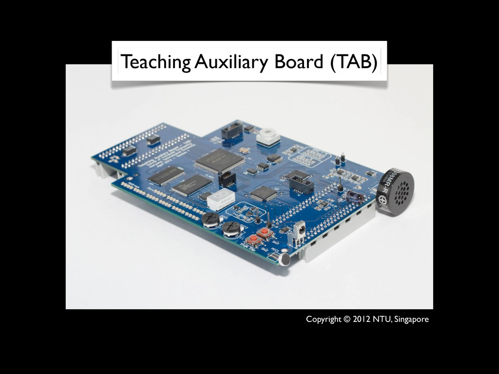
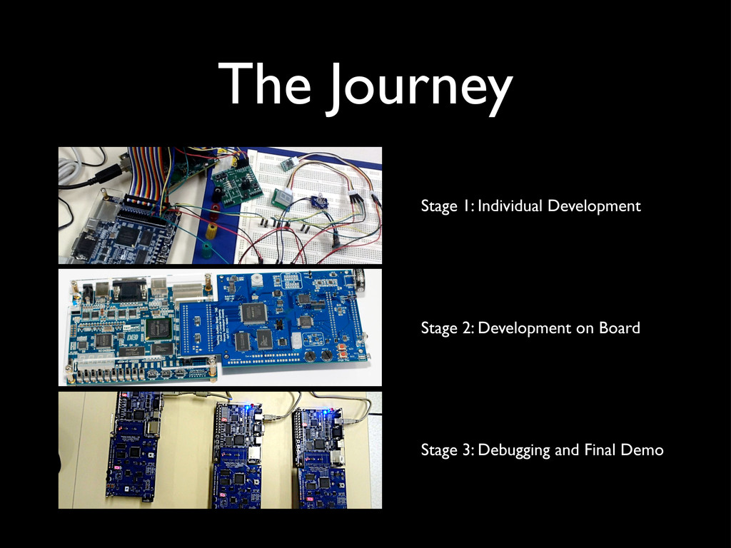
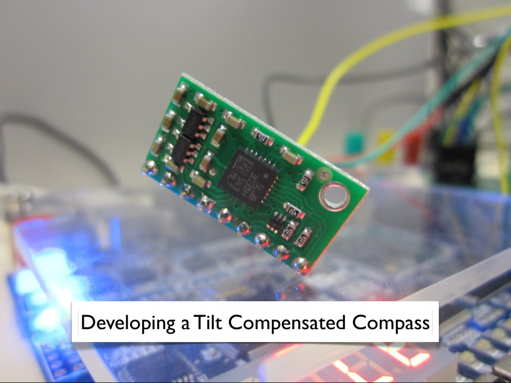
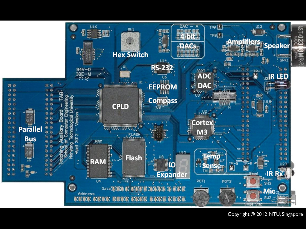
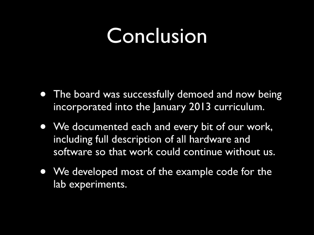
It talks about the development of a revolutionary new board for teaching undergraduate students in computer engineering course.

This presentation is what I gave to my faculty members at college as a requirement for the completion of my B.Tech degree.

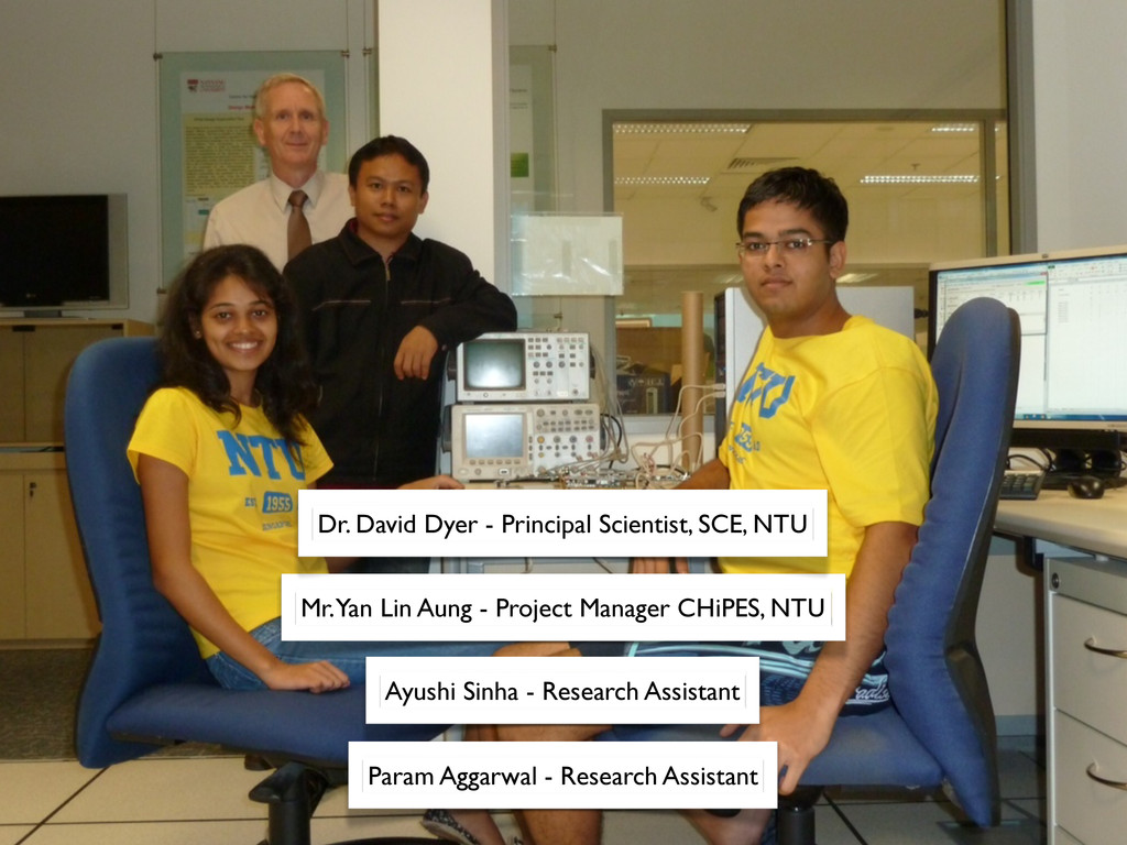
All work is copyright of NTU, Singapore and I claim no ownership. The project lead was Dr. David Dyer who designed the board.

This document only serves to demonstrate the kind of work I did at CHiPES, NTU, Singapore.

Param Aggarwal

July 21, 2012
Tweet

Other Decks in Education

Transcript

  1. By Param Aggarwal IEC2008009 Mr. Ajit Singh IIIT Allahabad Prof.

    Thambipillai Srikanthan NTU Singapore Under the guidance of
  2. Background • School of Computer Engineering at NTU is renewing

    their complete undergraduate curriculum • Dr. David Dyer, Principal Scientist at NTU, has designed a supporting board for it • It has been sent for fabrication to an EMS company February 2012
  3. Our Goal To take the newly fabricated and untested Teaching

    Auxiliary Board and develop on it, a full demonstration for the Chair of the School of Computer Engineering.
  4. The Challenge • The success of the demonstration would determine

    the inclusion of the new curriculum in the undergraduate course from January 2013. • Time Available: 128 days.
  5. Mr. Yan Lin Aung - Project Manager CHiPES, NTU Dr.

    David Dyer - Principal Scientist, SCE, NTU Ayushi Sinha - Research Assistant Param Aggarwal - Research Assistant
  6. set_clk(); write_with_start(LSM303_A); write_byte(CTRL_REG1_A & 0x7F); write_with_stop(ALL_AXIS_EN); write_with_start(LSM303_M); write_byte(MR_REG_M & 0x7F);

    write_with_stop(0); write_with_start(LSM303_A); write_byte(READ_A | 0x80); read_with_start(LSM303_A); axl = read_byte(); axh = read_byte(); ayl = read_byte(); ayh = read_byte(); azl = read_byte(); azh = read_with_stop(); write_with_start(LSM303_M); write_byte(READ_M | 0x80); read_with_start(LSM303_M); mxh = read_byte(); mxl = read_byte(); mzh = read_byte(); mzl = read_byte(); myh = read_byte(); myl = read_with_stop(); a->x = (axh << 8 | axl); a->y = (ayh << 8 | ayl); a->z = (azh << 8 | azl); m->x = (mxh << 8 | mxl); m->y = (myh << 8 | myl); m->z = (mzh << 8 | mzl); if(a->x > 32767) a->x = a->x - 65536; a- >x = -(a->x); if(a->y > 32767) a->y = a->y - 65536; a- >y = -(a->y); if(a->z > 32767) a->z = a->z - 65536; a- >z = -(a->z); if(m->x > 32767) m->x = m->x - 65536; m- >x = -(m->x); if(m->y > 32767) m->y = m->y - 65536; m- >y = -(m->y); if(m->z > 32767) m->z = m->z - 65536; m- >z = -(m->z);
  7. Normal Access Pink line: Bus Enable Bus is enabled for

    shorter time. Delayed Access Pink line: Bus Enable Bus is enabled for longer time. Simulated Slow Memory
  8. Hardware • The TAB board is a versatile platform developed

    to supplement the theoretical curriculum. • It can demonstrate principles like parallel bus transfers, serial peripheral interfacing (SPI) and inter-integrated circuit communication (I2C). • It can be used to explore optical, acoustic as well as wired communication. • Integrated accelerometer and magnetometer chip. • 16 channel 12-bit ADC and DAC subsystem capable of sampling audio.
  9. Running Code from External Memory extern countLED(uint32_t, uint32_t); int main

    (void){ uint32_t N = 0x01000001; uint32_t addr = 0xA0000000; // Set LEDs as outputs *((volatile uint32_t *)(addr + 0x4)) = 0xF; // Set all LEDs off *((volatile uint32_t *)(addr + 0x0)) = 0x0; countLED(N, addr); }
  10. AREA countLEDs, CODE, READONLY GLOBAL countLED countLED PROC MOVS r2,#0x00

    label ADDS r2,r2,#1 STR r2,[r1] CMP r0,r2 BNE label ENDP END
  11. #define DAC_A *((volatile uint16_t *) (0x80000050)) #define DAC_B *((volatile uint16_t

    *) (0x80000052)) typedef unsigned short uint16_t; int main (void){ uint16_t countUp; uint16_t i; while (1) { for(countUp = 0; countUp < 16; countUp++) { DAC_A = countUp; DAC_B = countUp; for(i = 0; i < 200; i++); } } }
  12. Flash Write Access • Interfacing Flash Memory is difficult because

    it is slower than processor. It needs to be polled to check for completion of write or erase operation. • There were three methods possible: • Hardware READY pin • Data Validity Check • Data Line Polling (Recommended) - Used
  13. Resistor Heater and the three temperature sensors. Resistor Heating using

    PWM I2C Sensor Analog Sensor Precision Analog Sensor
  14. assign TAB_SPI_CS = DE0_SPI_CS ? 1'bZ : 1'b0; assign TAB_SPI_SCLK

    = DE0_SPI_CS ? 1'bZ : DE0_SPI_CLK; assign TAB_SPI_SDI = DE0_SPI_CS ? 1'bZ : DE0_SPI_SDO; assign DE0_SPI_SDI = DE0_SPI_CS ? 1'bZ : TAB_SPI_SDO;
  15. Suppressing alternate CS • Cortex M3 uses 12-bit SPI and

    ADC/DAC subsystem uses 24-bit SPI. • As the SPI line passes through the CPLD, the CPLD was programmed to ignore alternate SPI chip-selects.
  16. Conclusion • The board was successfully demoed and now being

    incorporated into the January 2013 curriculum. • We documented each and every bit of our work, including full description of all hardware and software so that work could continue without us. • We developed most of the example code for the lab experiments.