Upgrade to Pro — share decks privately, control downloads, hide ads and more …

ECU Software Validation using Hardware-In-Loop Test Setup Automation

ECU Software Validation using Hardware-In-Loop Test Setup Automation

This presentation is among the Top 27 Best Papers/Practice/Tutorials selected, out of 460+ submissions received, to be presented @STC 2012.

Presentation Abstract

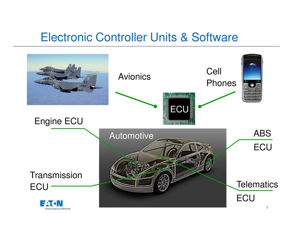
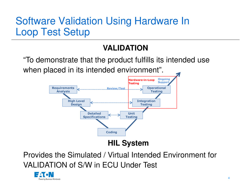
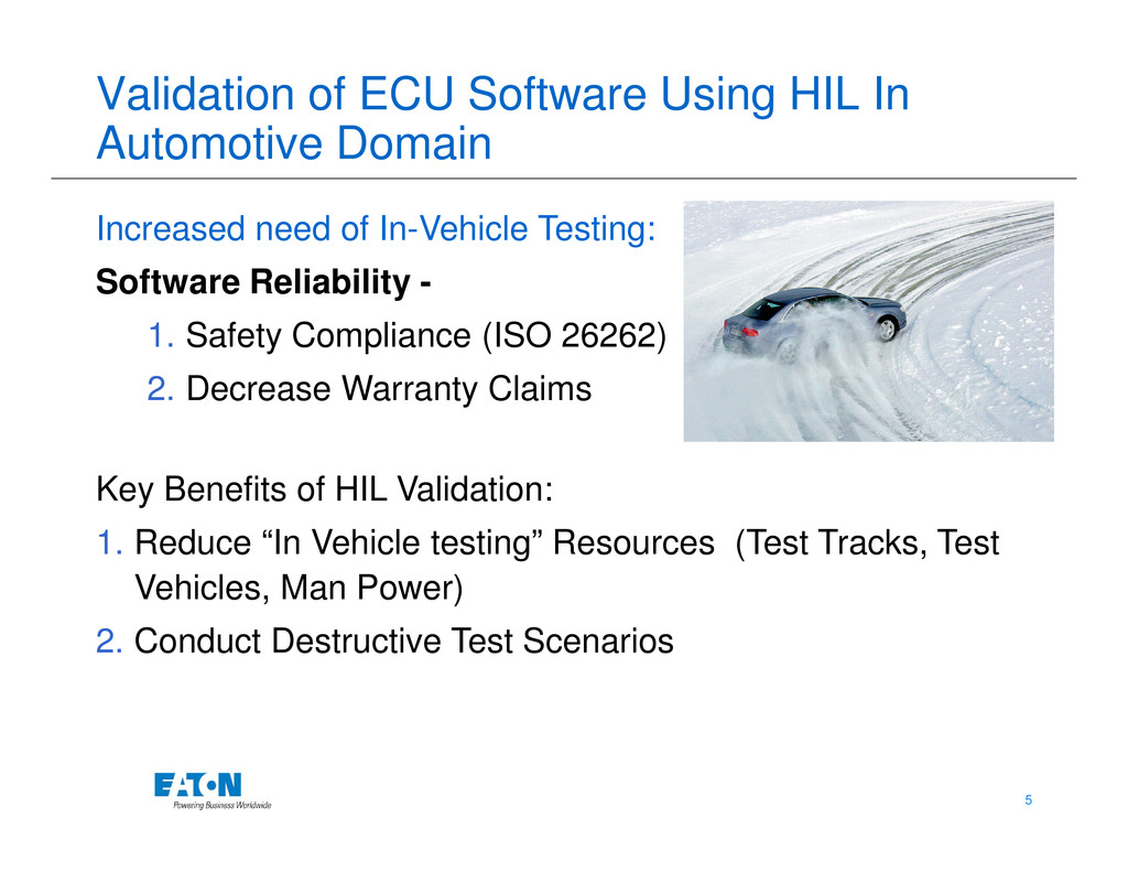
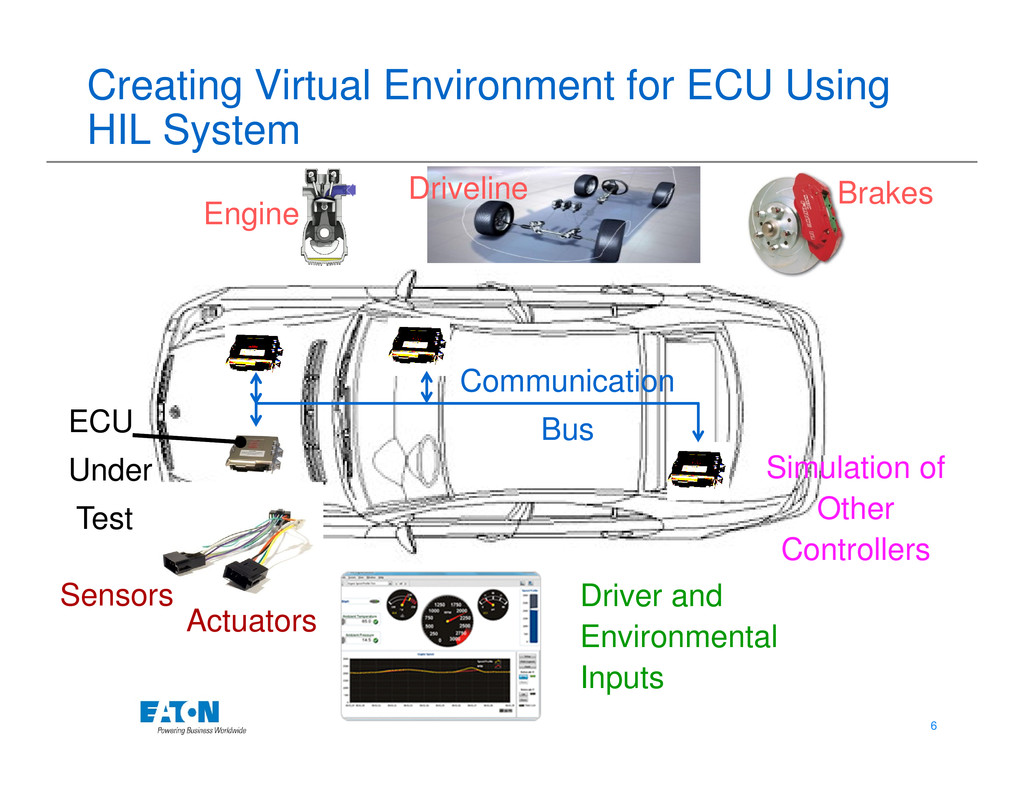
Hardware-In-loop simulation (HILS) has become an integral part of software development process used in the embedded system. The HIL Test Setup is extensively used for testing control algorithms implemented in the ECU Application Software. HIL simulation involves operating mechatronic systems particularly electronic control units (ECUs), in a closed loop with simulated components (environment, engine, vehicle, transmission) in real time to test ECU algorithms intensively in this virtual environment.
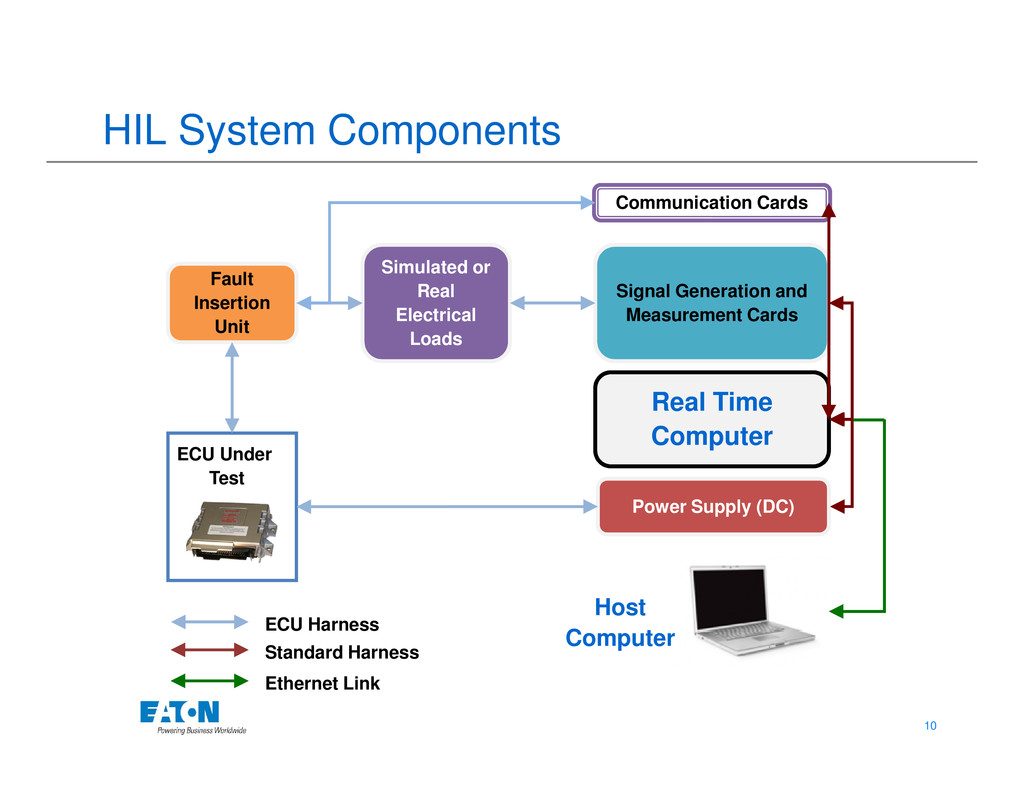
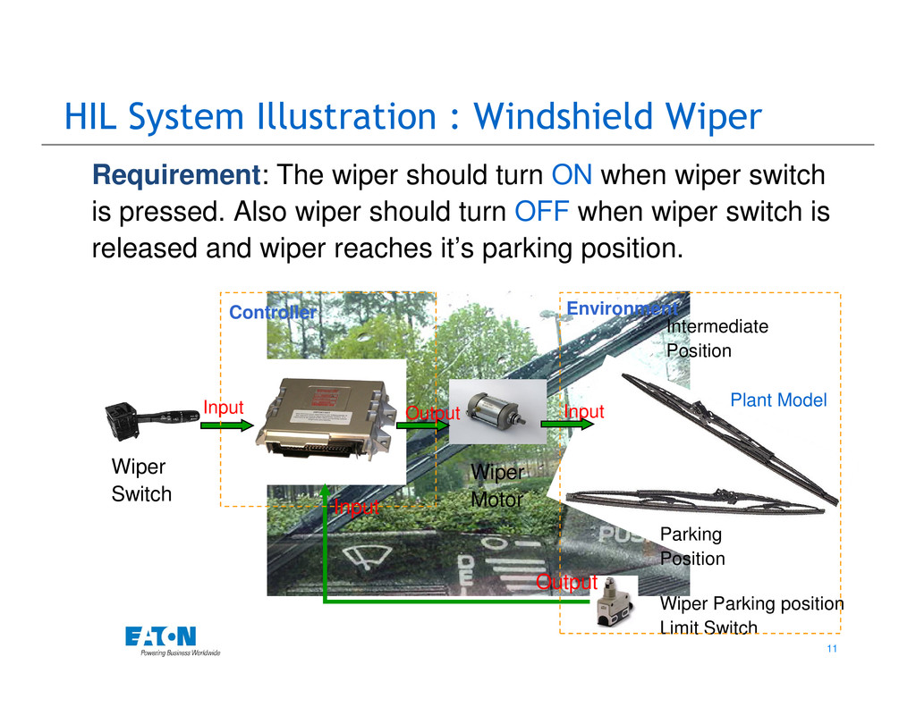
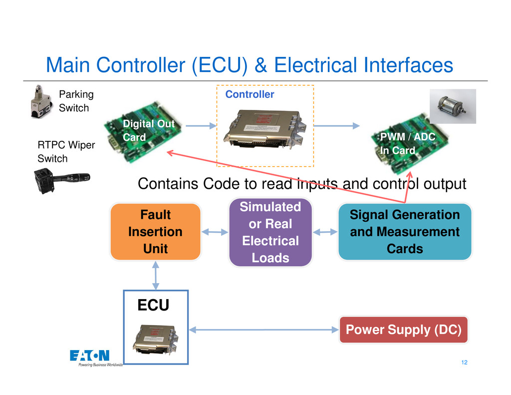
In this paper, a generic Hardware in Loop System is explained. The paper illustrates constituents of the HIL system which enable the functional and electrical diagnostic testing using the example of windshield wiper and transmission control module (TCM). The configuration and interfacing of the components used in the HIL system is also elaborated in this paper.

The accuracy of the testing results depends on how simulated components are designed compared to real world. The paper also throws light on some of the aspects of design of the simulated components like engine, transmission and vehicle.
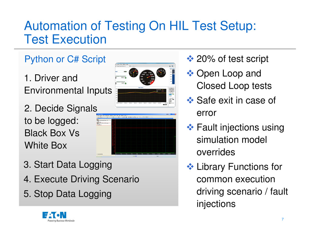
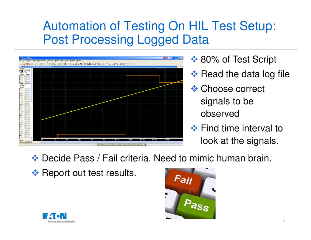
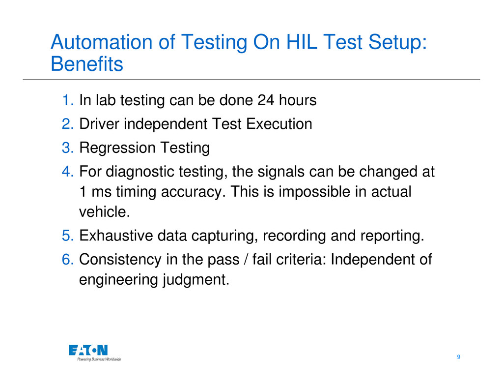
The paper also explains a framework which can be used to automate the testing conducted on HIL Test Setup. Automation test scripts can be written to execute different test scenarios on the test setup, read the data logs and give pass / fail verdicts. The time saving and repeatability achieved using the automation framework is explained.

About the Author

Shrirang Agashe is a mechanical engineer by education and has about 8 years of experience in the industry for Embedded Software development and validation.

He has completed 4.5 years at Eaton now and is working on HIL Test domain. He played a key role in setting up the HIL Test Setups for 3 programs for Eaton Transmission division. He was one of the members who architectured the HIL Test Automation framework using Python for the HIL Testing at Eaton. On the process side, he has participated in the CMMI level 3 audit at Eaton.

Prior to Eaton, he worked with KPIT Cummins and Tata Technologies. In KPIT he worked on development of diagnostics for Transmission Systems using Matlab Simulink. He has worked on developing the Matlab Stateflow models for Body Control Module (BCM) at Tata Technologies and has a good hands on experience with Matlab, m scripting, RTW code generation, Target Link Code generation and application coding using C. He also developed complete KWP 2K protocol stack using C.

More Decks by QAI Software Testing Conference

Other Decks in Technology

Transcript

  1. ECU Software Validation using ECU Software Validation using Hardware-In-Loop Test

    Setup Automation Shrirang Agashe Eaton Technologies Pvt. Ltd. EON Free Zone, Cluster C, Wing 1, MIDC, Kharadi, Pune – 411014 STC 2012: 5th & 6th December 2012
  2. Points To Be Covered • Electronic Control Units and Software

    • Validation in Automotive ECU Software • HIL – Virtual Test Environment • Automated Testing Using HIL Bench 2 2 • Automated Testing Using HIL Bench • HIL System Components • HIL System Illustration: Windshield wiper • HIL Testing Automation Illustration
  3. Electronic Controller Units & Software Avionics Cell Phones ECU 3

    3 Engine ECU Transmission ECU Automotive Telematics ECU ABS ECU ECU
  4. Software Validation Using Hardware In Loop Test Setup VALIDATION “To

    demonstrate that the product fulfills its intended use when placed in its intended environment”. Hardware-in-Loop Testing Requirements Analysis Operational Testing Review/Test Ongoing Support 4 4 HIL System Provides the Simulated / Virtual Intended Environment for VALIDATION of S/W in ECU Under Test High Level Design Detailed Specifications Coding Unit Testing Integration Testing
  5. Validation of ECU Software Using HIL In Automotive Domain Increased

    need of In-Vehicle Testing: Software Reliability - 1. Safety Compliance (ISO 26262) 2. Decrease Warranty Claims 5 5 Key Benefits of HIL Validation: 1. Reduce “In Vehicle testing” Resources (Test Tracks, Test Vehicles, Man Power) 2. Conduct Destructive Test Scenarios
  6. Creating Virtual Environment for ECU Using HIL System Engine Driveline

    Brakes Communication 6 6 ECU Under Test Driver and Environmental Inputs Communication Bus Simulation of Other Controllers Sensors Actuators
  7. Automation of Testing On HIL Test Setup: Test Execution 1.

    Driver and Environmental Inputs 2. Decide Signals to be logged: Python or C# Script 20% of test script Open Loop and Closed Loop tests Safe exit in case of error 7 7 to be logged: Black Box Vs White Box 3. Start Data Logging 4. Execute Driving Scenario 5. Stop Data Logging Fault injections using simulation model overrides Library Functions for common execution driving scenario / fault injections
  8. Automation of Testing On HIL Test Setup: Post Processing Logged

    Data 80% of Test Script Read the data log file Choose correct signals to be observed 8 8 Find time interval to look at the signals. Decide Pass / Fail criteria. Need to mimic human brain. Report out test results.
  9. Automation of Testing On HIL Test Setup: Benefits 1. In

    lab testing can be done 24 hours 2. Driver independent Test Execution 3. Regression Testing 4. For diagnostic testing, the signals can be changed at 1 ms timing accuracy. This is impossible in actual 9 9 1 ms timing accuracy. This is impossible in actual vehicle. 5. Exhaustive data capturing, recording and reporting. 6. Consistency in the pass / fail criteria: Independent of engineering judgment.
  10. HIL System Components Fault Insertion Unit Simulated or Real Electrical

    Loads Signal Generation and Measurement Cards Real Time Communication Cards 10 10 ECU under Test ECU Under Test Real Time Computer Power Supply (DC) Host Computer ECU Harness Standard Harness Ethernet Link
  11. HIL System Illustration : Windshield Wiper Requirement: The wiper should

    turn ON when wiper switch is pressed. Also wiper should turn OFF when wiper switch is released and wiper reaches it’s parking position. Intermediate Position Controller Environment 11 11 Parking Position Position Wiper Parking position Limit Switch Wiper Motor Wiper Switch Input Output Input Output Input Plant Model
  12. Main Controller (ECU) & Electrical Interfaces Parking Switch Digital Out

    Card PWM / ADC In Card RTPC Wiper Switch Controller Contains Code to read inputs and control output 12 12 Fault Insertion Unit ECU under Test ECU Simulated or Real Electrical Loads Signal Generation and Measurement Cards Power Supply (DC)
  13. Real Time Computer (RTPC) Signal Generation and Measurement Cards Real

    Time Communication Cards Intermediate Position Input Environment 13 13 Real Time Computer Power Supply (DC) Host Computer Parking Position Output Heart of the system / HIL System Controller Wiper Motor Parking switch
  14. Host Computer • Operator / Environment Inputs (GUI) • Static

    linking between RTPC, I / O Cards, Communication Cards Real Time Computer 14 14 Communication Cards • Runs the Automation Scripts Host Computer
  15. HIL Testing Automation Illustration: Windshield Wiper Scenario 1: When wiper

    switch was turned off and Wiper was in parking: Wiper motor turned off immediately. Scenario 2: When wiper switch was turned off and wiper was in intermediate position: Wiper motor turned off after wiper reached parking position 15 15 Wiper Motor Parking Switch Wiper Switch
  16. HIL Testing Automation Illustration Continued: Windshield Wiper Scenario 1 Execution:

    Turn on wiper switch. Wait for 2 minutes. Keep watching parking switch input. Turn off wiper switch as soon as parking position is reached. Scenario 2 Execution: Turn on wiper switch. Wait for 2 minutes. Turn off wiper switch as soon as wiper leaves parking position. 16 16 is reached. Post Processing: Check if Wiper motor is made off in 100 ms after wiper switch is off. Also verify if wiper was in parking position at the same instance. Post Processing: Check if Wiper motor is NOT made off after releasing wiper switch. Check wiper motor is made off in 100 ms after wiper reaches parking. Logged Variables: Wiper Switch (GUI), Parking Switch (Plant Model), Wiper Motor (Electrical)