Upgrade to Pro — share decks privately, control downloads, hide ads and more …

Simulated Field Environment - Test Automation & Continuous Regression Testing Framework

Simulated Field Environment - Test Automation & Continuous Regression Testing Framework

Best of the Best Award winning presentation by Nokia Siemens Networks @STC 2012.
Authors - Ethiraj Alwar & Matthew Houghton

Presentation Abstract

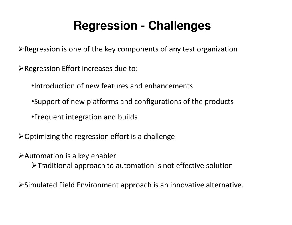
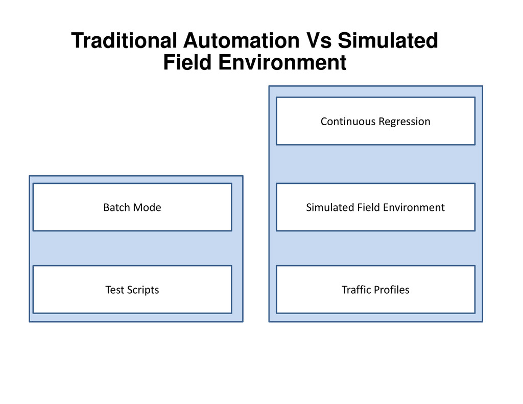
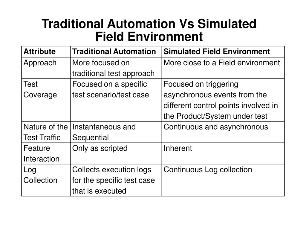
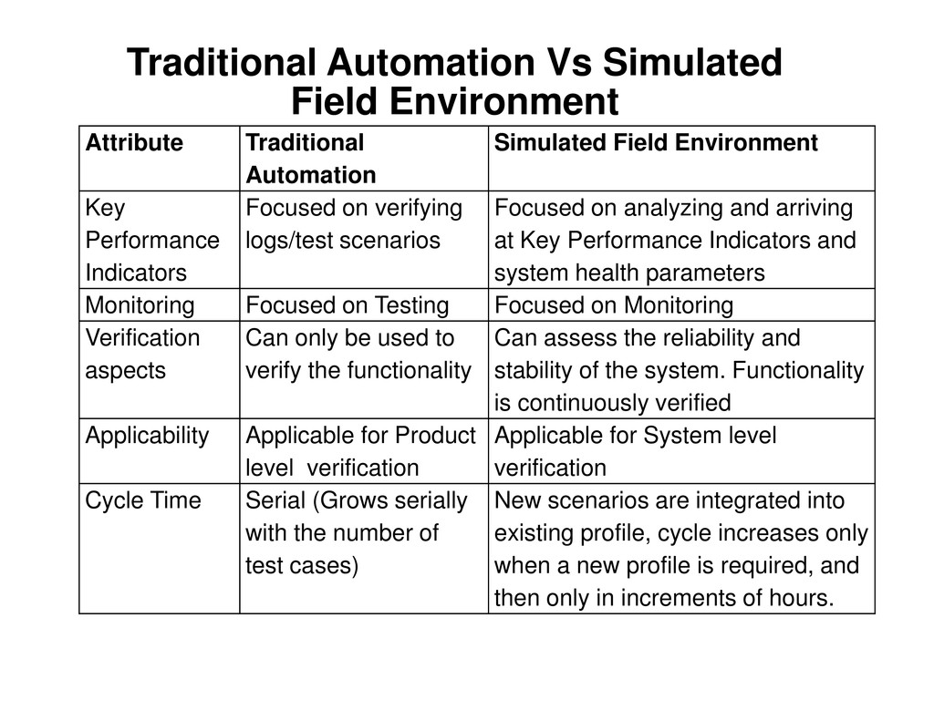
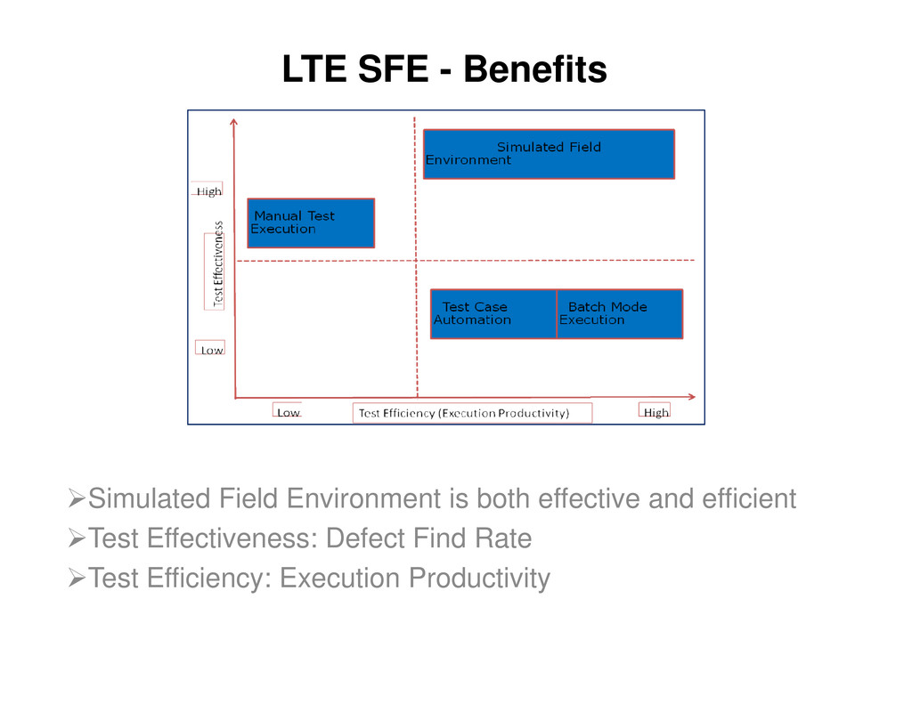
Key Challenge of Test Organization is Execution productivity for which automation is sought after as the first option. There is traditional approach to automation where test cases are scripted individually (and then batched) and there is Simulated Field Environment approach. Test case level automation may suffice the needs at unit/component level, but system level verification needs a much more robust framework that can trigger the asynchronous events under varying conditions that leads to multiple unforeseen interactions which yield defects that are often not found until field deployment.
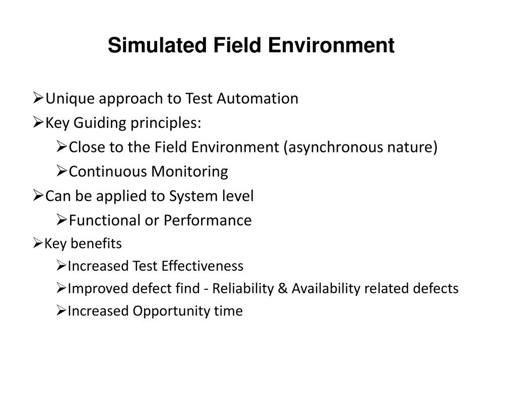
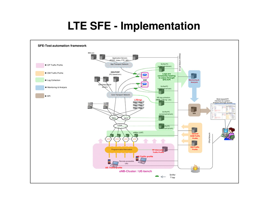
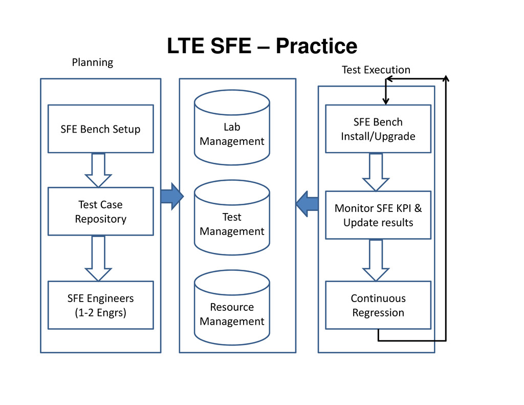
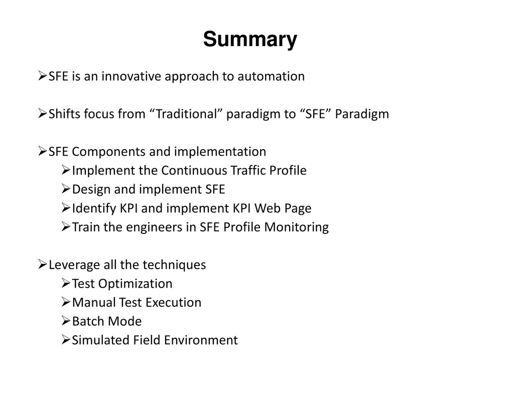
Simulated Field Environment is an innovative implementation of the Continuous integration and testing concept at the System Verification level which includes end-to-end verification of the system with multiple Network Elements. This framework was initially developed and institutionalized for testing the CDMA Network infrastructure (within the former Motorola Networks) and is now being used for LTE Infrastructure testing as well.
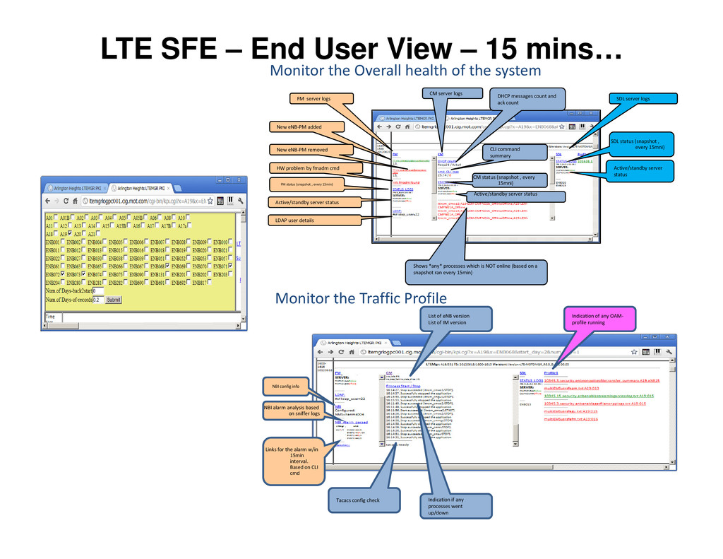
There are 4 key components of this framework – Continuous Traffic Profile which triggers both CP and OM traffic very much like field conditions, Continuous collection of both internal and external logs of all the involved network elements and interfaces, Continuous analysis of the logs to monitor the health of the system and Web based Key Performance Indicator page which the test engineer can monitor to identify any failures/issues and further debug/root-cause the issue.
This paper describes the Simulated Field environment approach, practice and experiences of LTE System Verification team. It describes the remarkable difference this environment enables in terms of test effectiveness.

About the Authors

Ethiraj Alwar has 20 years of experience in the Software industry, 15 years in Telecom industry in various positions related to System Engineering, Software development and System Verification in different domains such iDEN, CDMA, WiMax and LTE. Currently holding the position of System Verification Architect in the LTE System Verification Group. Has a B.E degree in Computer Science and Engineering from Madurai Kamaraj University, Tamilnad, India.

Matthew Houghton has 27 years of industry experience, 23 years in Mobile Broadband R&D with positions in SW Development, System Engineering, and System Verification. Originator of the Simulated Field Environment (SFE) approach to continuous regression, and architect of the SFE test automation framework. The SFE framework is designed to cost effectively transform a typical functional regression test environment into a field-like test environment yielding significantly more effective results.

More Decks by QAI Software Testing Conference

Other Decks in Technology

Transcript

  1. SIMULATED FIELD ENVIRONMENT TEST AUTOMATION & CONTINUOUS REGRESSION TESTING 12th

    Annual International Software Testing 2012 Ethiraj Alwar Matthew Houghton
  2. AGENDA Need for Simulated field environment? Challenges of Test Organizations

    Traditional approach to Automation Traditional Automation Vs Simulated Field Environment Simulated Field Environment in LTE System Verification End User View End User View Design Implementation Practice Benefits Results Summary
  3. Regression - Challenges Regression is one of the key components

    of any test organization Regression Effort increases due to: •Introduction of new features and enhancements •Support of new platforms and configurations of the products •Frequent integration and builds •Frequent integration and builds Optimizing the regression effort is a challenge Automation is a key enabler Traditional approach to automation is not effective solution Simulated Field Environment approach is an innovative alternative.
  4. Simulated Field Environment Unique approach to Test Automation Key Guiding

    principles: Close to the Field Environment (asynchronous nature) Continuous Monitoring Can be applied to System level Can be applied to System level Functional or Performance Key benefits Increased Test Effectiveness Improved defect find - Reliability & Availability related defects Increased Opportunity time
  5. Simulated Field Environment Continuous Regression Batch Mode Traditional Automation Vs

    Simulated Field Environment Traffic Profiles Simulated Field Environment Test Scripts Batch Mode
  6. Traditional Automation Vs Simulated Field Environment Attribute Traditional Automation Simulated

    Field Environment Approach More focused on traditional test approach More close to a Field environment Test Coverage Focused on a specific test scenario/test case Focused on triggering asynchronous events from the different control points involved in the Product/System under test the Product/System under test Nature of the Test Traffic Instantaneous and Sequential Continuous and asynchronous Feature Interaction Only as scripted Inherent Log Collection Collects execution logs for the specific test case that is executed Continuous Log collection
  7. Traditional Automation Vs Simulated Field Environment Attribute Traditional Automation Simulated

    Field Environment Key Performance Indicators Focused on verifying logs/test scenarios Focused on analyzing and arriving at Key Performance Indicators and system health parameters Monitoring Focused on Testing Focused on Monitoring Verification aspects Can only be used to verify the functionality Can assess the reliability and stability of the system. Functionality aspects verify the functionality stability of the system. Functionality is continuously verified Applicability Applicable for Product level verification Applicable for System level verification Cycle Time Serial (Grows serially with the number of test cases) New scenarios are integrated into existing profile, cycle increases only when a new profile is required, and then only in increments of hours.
  8. LTE SFE – End User View – 15 mins… FM

    server logs FM status (snapshot , every 15min) Active/standby server status LDAP user details CM server logs CLI command summary Active/standby server status DHCP messages count and ack count SDL server logs Active/standby server status Shows *any* processes which is NOT online (based on a snapshot ran every 15min) CM status (snapshot , every 15mni) SDL status (snapshot , every 15mni) HW problem by fmadm cmd New eNB-PM added New eNB-PM removed Monitor the Overall health of the system NBI config info NBI alarm analysis based on sniffer logs Links for the alarm w/in 15min interval. Based on CLI cmd Tacacs config check Indication if any processes went up/down Indication of any OAM- profile running List of eNB version List of IM version Monitor the Traffic Profile
  9. LTE SFE - Design HSS PCRF NBI Call Processing Operations

    & Maintenance Test Environment TContinuous Traffic Profile TContinuous Log Collection ContinuousT Log Analysis Dongle Dongle •eNB eNB MME EMS SGE & PGW •eNB eNB Dongle Dongle • System Verification verifies the CP and OM functionality in E2E lab configuration • Collection of logs through the SFE framework enables effective debugging and root-causing of issues. Collection Log Analysis TWeb based KPI Page Monitoring
  10. SFE-Test automation framework Core Transport Network PGW SGW App Transport

    Network Application Servers (IPERF, Video, FTP, IMS..) NTP/DNS/DHCP servers HSS/PCRF (PC-based sim) SnifferPC (wireshark/tshark) SnifferPC (wireshark/tshark) SV Lab Network (RDNet) LTEmgr NE-log-collection (MME, LTEmgr..etc) Logs are constantly feeding to users through SFE-KPI GW Log Collection IMS-sim CP Traffic Profile Monitoring & Analysis OM Traffic Profile Monitoring & Analysis KPI Web-based KPI interface for system- analysis and logs access LTE SFE - Implementation Sniffer T-tap eNB eNB eNB eNB L2SW MLS MLS MME MME Programmable Attenuators eNBpc (LMT) SnifferPC (wireshark/tshark) SnifferPC (wireshark/tshark) Office Network Remote accessible UEs eNB-Cluster / UE-bench UE- Traffic profile UE-Traffic profile RF-Attenuator Traffic Profile General OAM-Traffic Profile GUI-Traffic Profile KPI analysis and logs access
  11. LTE SFE – Practice SFE Bench Setup Test Case Lab

    Management SFE Bench Install/Upgrade Monitor SFE KPI & Planning Test Execution Test Case Repository Test Management Resource Management SFE Engineers (1-2 Engrs) Monitor SFE KPI & Update results Continuous Regression
  12. LTE SFE - Benefits Simulated Field Environment is both effective

    and efficient Test Effectiveness: Defect Find Rate Test Efficiency: Execution Productivity
  13. LTE SFE - Results Metric Benefits Maturity • Cornerstone of

    regression for E2E CDMA Infrastructure since 2005. • 2nd generation framework designed and implemented in 2009 for testing E2E LTE Infrastructure (7 releases and counting) Incremental Effort • Initial effort is fully aligned with designing and implementing the test environment. In our case the SFE was designed and implemented by a team of 4 test engineers. implemented by a team of 4 test engineers. • A pair of engineers (2) maintain and monitor a single SFE profile Test Efficiency • Similar improvements in efficiency to traditional approaches to automation. Test Effectiveness • Continuous nature of this approach yielded a dramatic increase in reliability / availability defects (well over 100%) • Significant increase in functional defects found (over 30%)
  14. LTE SFE – Return on Investment Category Initial Year (USD)

    Subsequent Years (USD) Equipment Cost $25K None Engineering Cost (4 eng) $288K $288K Reduction in Cost of Poor Quality $900K $1,800K Return on Investment $587K $1,512K Equipment and Engineering costs are incremental to more traditional approaches to automation. Engineering cost is mainly for SFE test environment development. Engineering cost of 72K USD per annum is considered. Reduction in Cost of Poor Quality due to incremental increase in defects found (average of 1.5 per month) Complex defects that would not be found in more traditional environments Otherwise would have become escaped defects (cost of $50K per escape) Partial (50%) return in initial year; full return in subsequent years
  15. Summary SFE is an innovative approach to automation Shifts focus

    from “Traditional” paradigm to “SFE” Paradigm SFE Components and implementation Implement the Continuous Traffic Profile Design and implement SFE Identify KPI and implement KPI Web Page Train the engineers in SFE Profile Monitoring Leverage all the techniques Test Optimization Manual Test Execution Batch Mode Simulated Field Environment
  16. Acknowledgements Contributions from Pak Hui, Shyam Tak and Alex Reyther

    - who developed the SFE Framework for the CDMA & LTE Network Infrastructure – to the content of this paper. Several people have been involved in the SFE automation efforts over many years, not all of can be individually named. We would like to mention the contributions from the automation team - B R to mention the contributions from the automation team - B R Prashanth, Ankit Kapoor, Kavitha N & team Efforts from LTE Functional Regression Team including Amit Das, Shailesh Kumar, Vivek Bangera.