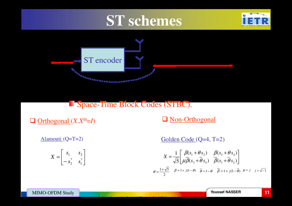
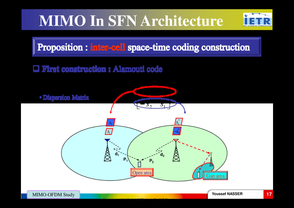
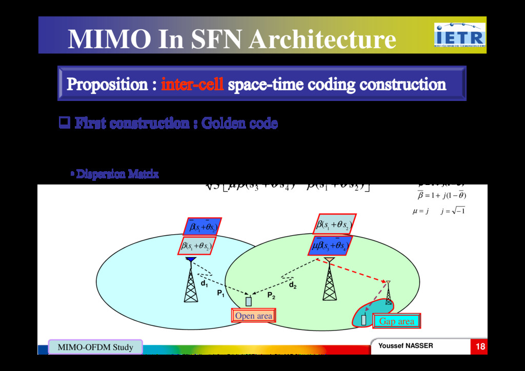
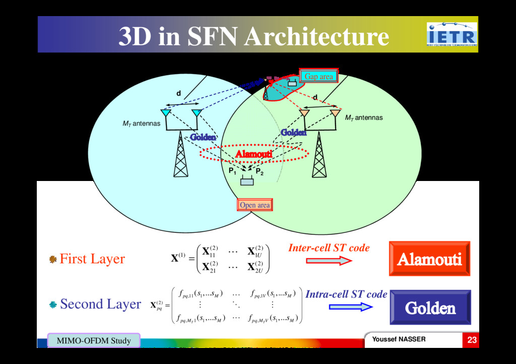
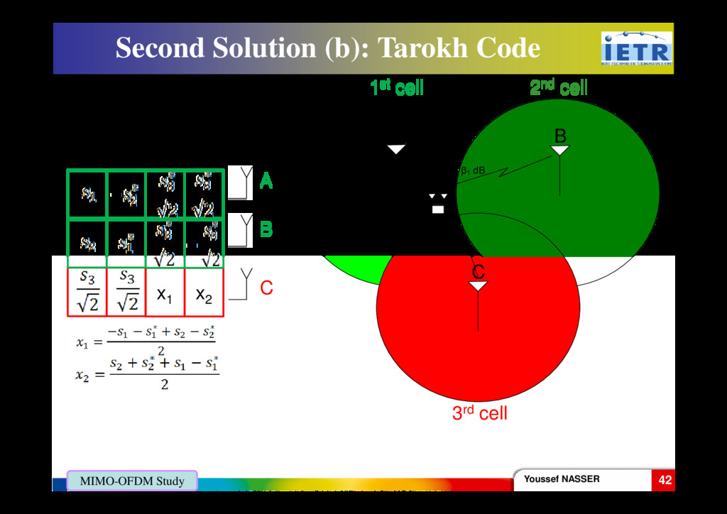
= = = ) ,..., ( ... ) ,..., ( ) ,..., ( ... ) ,..., ( 1 21 1 12 2 1 21 1 11 1 Q Q Q Q s s f s s f x s s f s s f x X (s1 ,…,sQ ) ST encoder Q T ST rate L=Q/T Space-Time Block Codes (STBC). Youssef NASSER 11 MIMO-OFDM Study Orthogonal (X.XH=I) Non-Orthogonal − = * 1 * 2 2 1 s s s s X Alamouti (Q=T=2) Space-Time Block Codes (STBC). + + + + = ) ( ) ( ) ( ) ( 5 1 2 1 4 3 4 3 2 1 s s s s s s s s X θ β θ β µ θ β θ β 2 5 1+ = θ θ θ − =1 ) 1 ( 1 θ β − + = j ) 1 ( 1 θ β − + = j j = µ 1 − = j Golden Code (Q=4, T=2)
![[ ] 1 2 tr s s = X MIMO](https://files.speakerdeck.com/presentations/6517b9120e1d4af8af8f5562cee0bc07/slide_18.jpg)
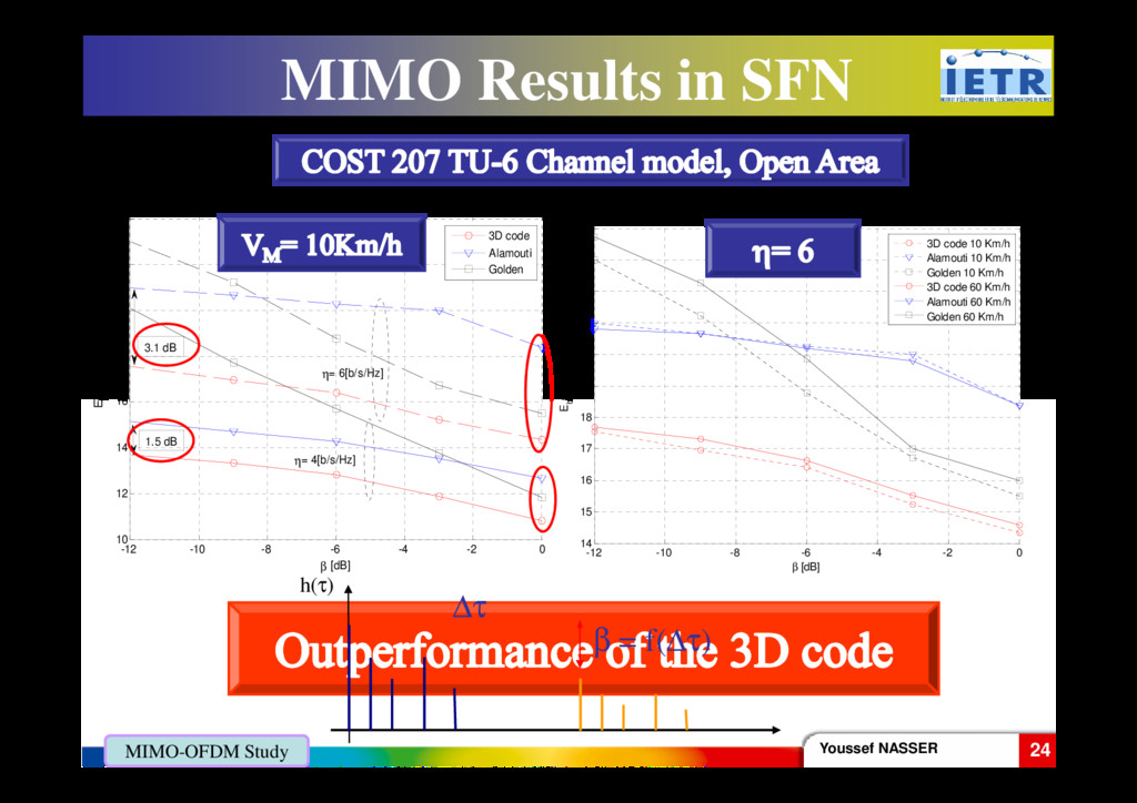
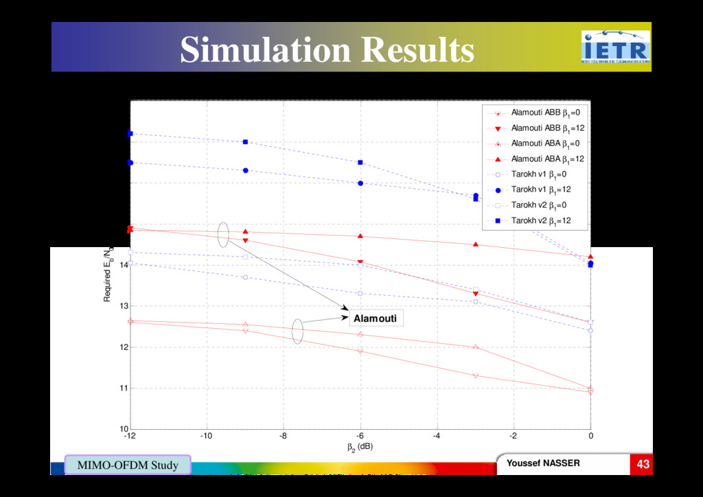
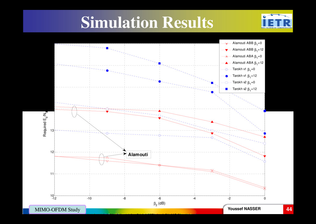
![12 14 16 18 [dB] to obtain a BER=10-4 Required](https://files.speakerdeck.com/presentations/6517b9120e1d4af8af8f5562cee0bc07/slide_33.jpg)