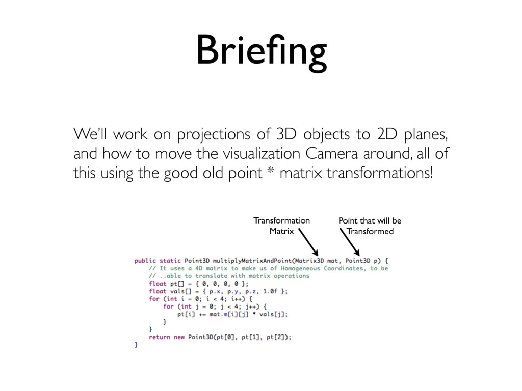
and how to move the visualization Camera around, all of this using the good old point * matrix transformations! Transformation Matrix Point that will be Transformed Briefing
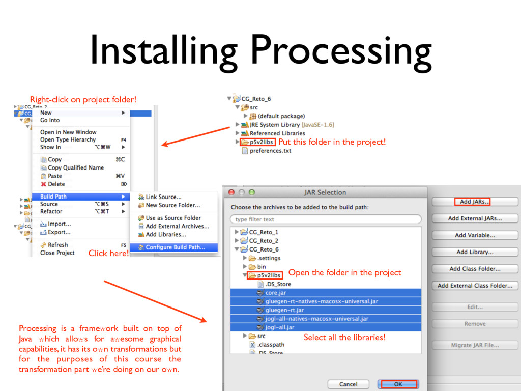
Click here! Open the folder in the project Select all the libraries! Processing is a framework built on top of Java which allows for awesome graphical capabilities, it has its own transformations but for the purposes of this course the transformation part we’re doing on our own. Installing Processing
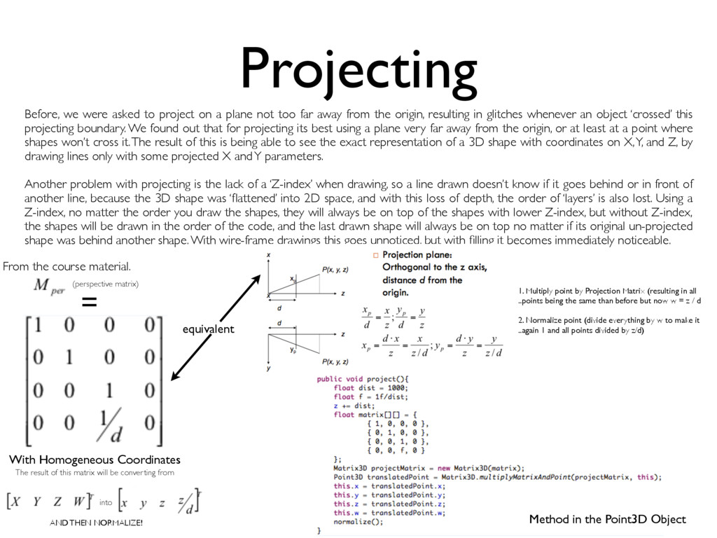
not too far away from the origin, resulting in glitches whenever an object ‘crossed’ this projecting boundary. We found out that for projecting its best using a plane very far away from the origin, or at least at a point where shapes won’t cross it. The result of this is being able to see the exact representation of a 3D shape with coordinates on X, Y, and Z, by drawing lines only with some projected X and Y parameters. Another problem with projecting is the lack of a ‘Z-index’ when drawing, so a line drawn doesn’t know if it goes behind or in front of another line, because the 3D shape was ‘flattened’ into 2D space, and with this loss of depth, the order of ‘layers’ is also lost. Using a Z-index, no matter the order you draw the shapes, they will always be on top of the shapes with lower Z-index, but without Z-index, the shapes will be drawn in the order of the code, and the last drawn shape will always be on top no matter if its original un-projected shape was behind another shape. With wire-frame drawings this goes unnoticed, but with filling it becomes immediately noticeable. = From the course material. (perspective matrix) The result of this matrix will be converting from With Homogeneous Coordinates into AND THEN NORMALIZE! equivalent 1. Multiply point by Projection Matrix (resulting in all ..points being the same than before but now w = z / d 2. Normalize point (divide everything by w to make it ..again 1 and all points divided by z/d) Method in the Point3D Object
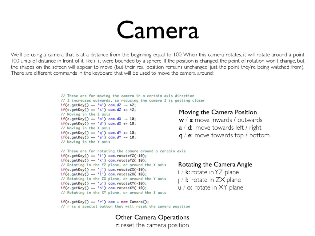
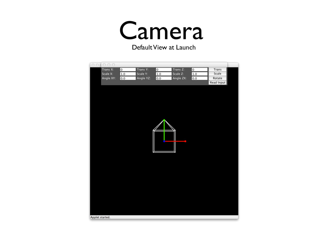
/ outwards a / d: move towards left / right q / e: move towards top / bottom Rotating the Camera Angle i / k: rotate in YZ plane j / l: rotate in ZX plane u / o: rotate in XY plane Other Camera Operations r: reset the camera position We’ll be using a camera that is at a distance from the beginning equal to 100. When this camera rotates, it will rotate around a point 100 units of distance in front of it, like if it were bounded by a sphere. If the position is changed, the point of rotation won’t change, but the shapes on the screen will appear to move (but their real position remains unchanged, just the point they’re being watched from). There are different commands in the keyboard that will be used to move the camera around:
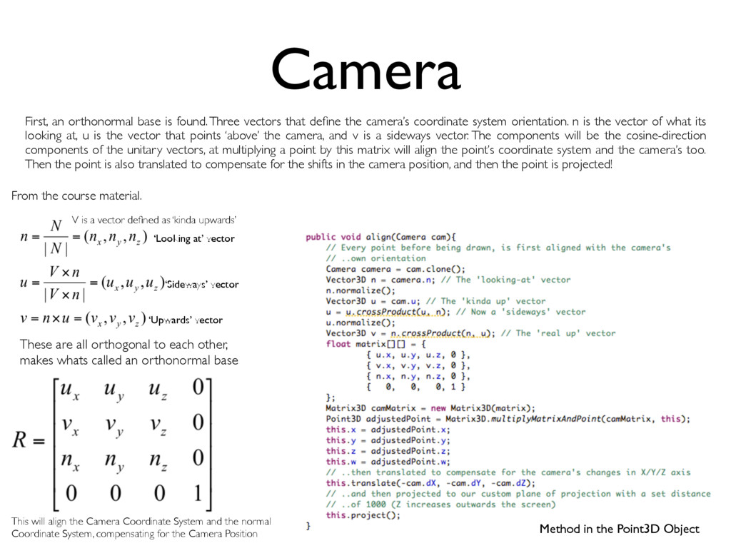
define the camera’s coordinate system orientation. n is the vector of what its looking at, u is the vector that points ‘above’ the camera, and v is a sideways vector. The components will be the cosine-direction components of the unitary vectors, at multiplying a point by this matrix will align the point’s coordinate system and the camera’s too. Then the point is also translated to compensate for the shifts in the camera position, and then the point is projected! ‘Looking at’ vector From the course material. ‘Sideways’ vector ‘Upwards’ vector These are all orthogonal to each other, makes whats called an orthonormal base V is a vector defined as ‘kinda upwards’ This will align the Camera Coordinate System and the normal Coordinate System, compensating for the Camera Position Method in the Point3D Object
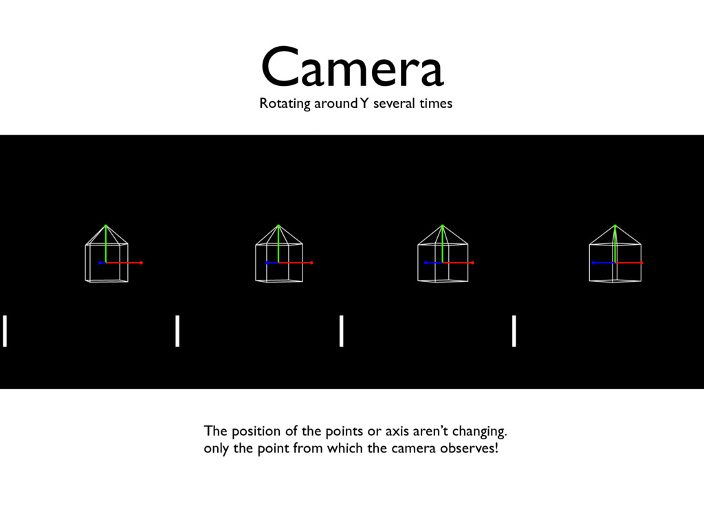
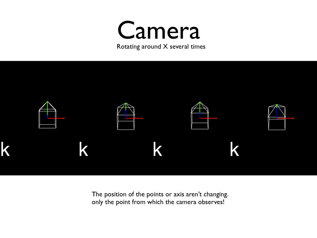
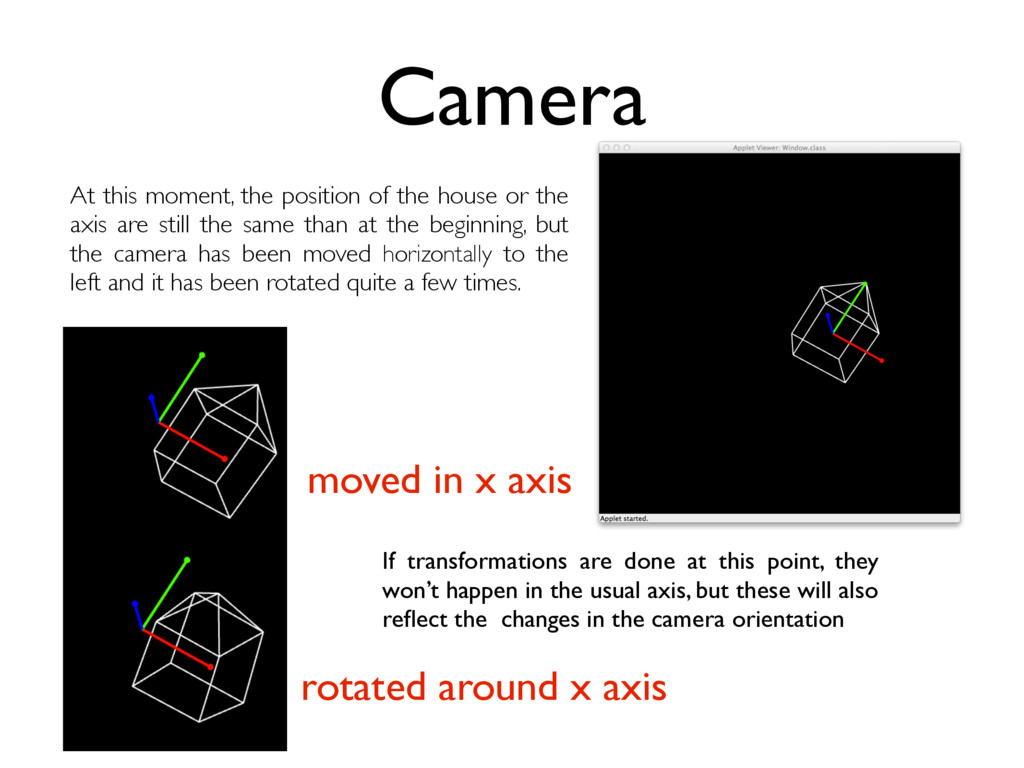
the axis are still the same than at the beginning, but the camera has been moved horizontally to the left and it has been rotated quite a few times. If transformations are done at this point, they won’t happen in the usual axis, but these will also reflect the changes in the camera orientation moved in x axis rotated around x axis