Upgrade to Pro — share decks privately, control downloads, hide ads and more …

Caterpillar_Cat_980G_II_Wheel_Loader__Prefix_AWH__Service_Repair_Manual__AWH00001_and_up_.pdf

dcfv
May 20, 2024
4

 Caterpillar_Cat_980G_II_Wheel_Loader__Prefix_AWH__Service_Repair_Manual__AWH00001_and_up_.pdf

dcfv

May 20, 2024
Tweet

More Decks by dcfv

Transcript

  1. Shutdown SIS Previous Screen Product: WHEEL LOADER Model: 980G II

    WHEEL LOADER AWH Configuration: 980G II Wheel Loader AWH00001-UP (MACHINE) POWERED BY 3406 Engine Disassembly and Assembly 3406E and 3456 Engines for Caterpillar Built Machines Media Number -RENR1364-06 Publication Date -01/05/2008 Date Updated -20/05/2008 i02110801 Camshaft - Remove SMCS - 1210-011 Removal Procedure Table 1 Required Tools Tool Part Number Part Description Qty A 9U-7257 Cradle 1 B 9U-7256 Guide 1 C 9U-7225 Camshaft Pilot 2 D 9U-7240 Camshaft Hook 2 Start By: A. Remove the camshaft gear. Refer to Disassembly and Assembly, "Camshaft Gear - Remove and Install". B. Remove the rocker arms and the rocker shafts. Refer to Disassembly and Assembly, "Rocker Arm and Shaft - Remove". NOTICE Keep all parts clean from contaminants. Contaminants may cause rapid wear and shortened component life.
  2. NOTICE Care must be taken to ensure that fluids are

    contained during performance of inspection, maintenance, testing, adjusting and repair of the product. Be prepared to collect the fluid with suitable containers before opening any compartment or disassembling any component containing fluids. Refer to Special Publication, NENG2500, "Caterpillar Tools and Shop Products Guide" for tools and supplies suitable to collect and contain fluids on Caterpillar products. Dispose of all fluids according to local regulations and mandates. Illustration 1 g01028806 NOTICE Do not turn the crankshaft or the camshaft while the camshaft gear is removed. If the front gear group is not correctly timed during installation, interference can occur between the pistons and the valves, resulting in damage to the engine. 1. Remove bolts (2) and thrust plate (1) .
  3. Illustration 2 g00576209 2. Remove seal assembly (3) and adapter

    (4) . Illustration 3 g00576240 3. Remove O-ring seals (5) and (6) from seal assembly (3) . NOTICE Care must be used when removing the camshaft to not damage the highly finshed surfaces of both the camshaft and camshaft bearings
  4. Illustration 4 g00509797 Illustration 5 g00581441 4. Use the bolts

    for the rocker arm shaft assembly to install Tooling (A) at Location (Y) . Illustration 6 g00581442 5. Install Tooling (B) on front housing (7). Do not tighten the bolts for Tooling (B) at this time.
  5. Illustration 7 g01074729 Note: It is necessary to install Tooling

    (C) on the camshaft. Tooling (C) will support the rear of camshaft (8) as the camshaft is moved out of the cylinder head and into Tooling (B) . 6. Move camshaft (8) forward and install one Tooling (C) in the end of camshaft (8). Again, move the camshaft forward and install remaining Tooling (C) into the back of first Tooling (C) . 7. Position camshaft (8) into the bore of Tooling (B). Tighten the bolts that hold Tooling (B) to the front housing. Illustration 8 g00581444 Note: Avoid lifting camshaft (8) with Tooling (D). The camshaft should rest on Tooling (A). Lifting of the camshaft can cause misalignment as the camshaft is removed, resulting in damage to the camshaft bearings.
  6. https://www.aservicemanualpdf.com/ My Dear Friend! Thank you very much for visiting.

    Full manual if required, please enter the following URL into your browser. https://www.aservicemanualpdf.com/
  7. Illustration 9 g00581445 8. Remove camshaft (8), as follows: a.

    Use Tooling (D) to move camshaft (8) toward the front of the engine. Reposition Tooling (D), as needed. b. Move camshaft (8) far enough out of the cylinder head in order to attach a suitable lifting device. c. Keep the camshaft level while the camshaft is being removed from the cylinder head. The weight of the camshaft is approximately 39 kg (86 lb). Alternative Removal Procedure Table 2 Required Tools Tool Part Number Part Description Qty E (1) 177-8001 Sleeve 1 F 177-8002 Adapter 1 G 6L-4697 Bolts 3 ( 1 ) Part of 177-8003 Engine Tool Group Start By: A. Remove the camshaft gear. Refer to Disassembly and Assembly, "Camshaft Gear - Remove and Install". B. Remove the rocker arms and the rocker shafts. Refer to Disassembly and Assembly, "Rocker Arm and Shaft - Remove". Note: This is an optional procedure to remove the camshaft. The preceding tool list shows the required tooling for removing the camshaft from the front of the engine or the rear of the engine. NOTICE
  8. Keep all parts clean from contaminants. Contaminants may cause rapid

    wear and shortened component life. NOTICE Care must be taken to ensure that fluids are contained during performance of inspection, maintenance, testing, adjusting and repair of the product. Be prepared to collect the fluid with suitable containers before opening any compartment or disassembling any component containing fluids. Refer to Special Publication, NENG2500, "Caterpillar Tools and Shop Products Guide" for tools and supplies suitable to collect and contain fluids on Caterpillar products. Dispose of all fluids according to local regulations and mandates. Illustration 10 g01028806 NOTICE Do not turn the crankshaft or the camshaft while the camshaft gear is removed. If the front gear group is not correctly timed during installation, interference can occur between the pistons and the valves, resulting in damage to the engine. 1. Remove bolts (2) and thrust plate (1) .
  9. Illustration 11 g00576209 2. Remove seal assembly (3) and adapter

    (4) . Illustration 12 g00576240 3. Remove O-ring seals (5) and (6) from seal assembly (3) .
  10. Illustration 13 g01043575 4. Remove screws (7) and cover (8)

    . NOTICE Care must be used when removing the camshaft to not damage the highly finshed surfaces of both the camshaft and camshaft bearings Illustration 14 g01024825 Note: Carefully align Tooling (F) with the end of the camshaft. If the adapter and the camshaft are not aligned, the camshaft may not be removed. The adapter and camshaft bearing will interfere. 5. To remove the camshaft from the rear of the engine, install Tooling (F) on the front of the camshaft with Tooling (G) . 6. Install Tooling (E) . Illustration 15 g01043577
  11. 7. Carefully slide the camshaft to the rear of the

    engine for removal. Use two technicians to remove the camshaft. Keep the camshaft level while the camshaft is being removed from the cylinder head. The weight of the camshaft is approximately 39 kg (86 lb). Illustration 16 g01024826 8. To remove the camshaft from the front of the engine, install Tooling (E) on the rear of the camshaft. 9. Carefully slide the camshaft to the front of the engine for removal. Use two technicians to remove the camshaft. Keep the camshaft level while the camshaft is being removed from the cylinder head. The weight of the camshaft is approximately 39 kg (86 lb). Copyright 1993 - 2022 Caterpillar Inc. All Rights Reserved. Private Network For SIS Licensees. Sat Feb 19 21:58:02 UTC+0800 2022
  12. Shutdown SIS Previous Screen Product: WHEEL LOADER Model: 980G II

    WHEEL LOADER AWH Configuration: 980G II Wheel Loader AWH00001-UP (MACHINE) POWERED BY 3406 Engine Disassembly and Assembly 3406E and 3456 Engines for Caterpillar Built Machines Media Number -RENR1364-06 Publication Date -01/05/2008 Date Updated -20/05/2008 i02963221 Camshaft - Install SMCS - 1210-012 Installation Procedure Table 1 Required Tools Tool Part Number Part Description Qty A 9U-7257 Cradle 1 B 9U-7256 Guide 1 C 9U-7225 Camshaft Pilot 2 D 9U-7240 Camshaft Hook 2 H 9U-7243 Alignment Sleeve 1 J 9S-3263 Thread Lock Compound 1 K 8T-2998 Lubricant 1 NOTICE Keep all parts clean from contaminants. Contaminants may cause rapid wear and shortened component life. 1. Ensure that the camshaft and camshaft bearings are thoroughly clean. Lubricate the camshaft lobes with a 50/50 mixture of Tooling (K) and clean engine oil. Apply a thin coat of clean engine oil on the camshaft bearings.
  13. Illustration 1 g00509797 Illustration 2 g00581441 2. Install Tooling (A)

    on the cylinder head at Location (Y) . Illustration 3 g01024862
  14. 3. Install Tooling (B) on front housing (7) . Do

    not tighten the bolts that hold Tooling (B) to front housing (7) at this time. 4. Use Tooling (H) to align Tooling (B) with the camshaft bearings. Tighten the bolts that hold Tooling (B) to front housing (7) . Remove Tooling (H) . Note: Tooling (H) should move freely from the bore of Tooling (B) . Illustration 4 g00581445 5. Install Tooling (C) in the end of camshaft (8) . Note: Rotate the camshaft during installation. This will prevent the camshaft from binding in the camshaft bearings. 6. Use a suitable lifting device in order to position camshaft (8) into Tooling (B) and the cylinder head. The weight of the camshaft is approximately 39 kg (86 lb). Illustration 5 g00581444
  15. Illustration 6 g00581443 Note: Tooling (C) must be removed before

    the camshaft can be completely installed in the cylinder head. 7. Remove the lifting device. Rotate the camshaft during installation. Use care not to allow the end of the camshaft and Tooling (C) to drop. Use Tooling (D) to assist in aligning camshaft (8) with the camshaft bearings. 8. Remove Tooling (C) and finish installing camshaft (8) in the bore. 9. Remove Tooling (A) and Tooling (B) . Illustration 7 g00576240
  16. Illustration 8 g00576839 10. Install O-ring seals (5) and (6)

    in seal assembly (3) . Lubricate seal (6) with Tooling (K) . 11. Install seal assembly (3) . Position adapter (4) . Ensure that the dowel in adapter (4) engages the hole in the camshaft. 12. Position thrust plate (1) . Apply Tooling (J) to bolts (2) . Hold thrust plate (1) in position and install bolts (2) . Evenly tighten bolts (2) until seal assembly (3) and O-ring seal (5) are seated against the cylinder head. Note: Be careful in order to ensure that O-ring seal (5) stays in the groove in seal assembly (3) . End By: a. Install the rocker arms and the rocker shafts. Refer to Disassembly and Assembly, "Rocker Arm and Shaft - Install". b. Install the camshaft gear. Refer to Disassembly and Assembly, "Camshaft Gear - Remove and Install". Alternative Installation Procedure Table 2 Required Tools Tool Part Number Part Description Qty E (1) 177-8001 Sleeve 1 F 177-8002 Adapter 1 G 6L-4697 Bolts 3 J 9S-3263 Thread Lock Compound 1 K 8T-2998 Lubricant 1 ( 1 ) Part of 177-8003 Engine Tool Group
  17. NOTICE Keep all parts clean from contaminants. Contaminants may cause

    rapid wear and shortened component life. 1. Ensure that the camshaft and camshaft bearings are thoroughly clean. Lubricate the camshaft lobes with a 50/50 mixture of Tooling (K) and clean engine oil. Apply a thin coat of clean engine oil on the camshaft bearings. Illustration 9 g01043587 2. Install Tooling (F) on the front of camshaft (9) with Tooling (G) . 3. Install Tooling (E) . 4. Use two technicians to install the camshaft. Carefully slide camshaft (9) into the cylinder head from the rear of the engine. Keep the camshaft level while the camshaft is being installed in the cylinder head. The weight of the camshaft is approximately 39 kg (86 lb). 5. Remove Tooling (F) .
  18. Illustration 10 g01043589 6. Install Tooling (F) on the end

    of the camshaft. 7. Use two technicians to install the camshaft. Carefully slide camshaft (9) into the cylinder head from the rear of the engine. Keep the camshaft level while the camshaft is being installed in the cylinder head. The weight of the camshaft is approximately 39 kg (86 lb). 8. Remove Tooling (F) . Illustration 11 g01043575 9. Position cover (8) on the rear of the cylinder head. Install bolts (7) . Illustration 12 g00576240
  19. Illustration 13 g00576839 10. Install O-ring seals (5) and (6)

    in seal assembly (3) . Lubricate seal (6) with Tooling (K) . 11. Install seal assembly (3) . Position adapter (4) . Ensure that the dowel in adapter (4) engages the hole in the camshaft. 12. Position thrust plate (1) . Apply Tooling (J) to bolts (2) . Hold thrust plate (1) in position and install bolts (2) . Evenly tighten bolts (2) until seal assembly (3) and O-ring seal (5) are seated against the cylinder head. Note: Be careful in order to ensure that O-ring seal (5) stays in the groove in seal assembly (3) . End By: a. Install the rocker arms and the rocker shafts. Refer to Disassembly and Assembly, "Rocker Arm and Shaft - Install". b. Install the camshaft gear. Refer to Disassembly and Assembly, "Camshaft Gear - Remove and Install". Copyright 1993 - 2022 Caterpillar Inc. All Rights Reserved. Private Network For SIS Licensees. Sat Feb 19 21:58:58 UTC+0800 2022
  20. Shutdown SIS Previous Screen Product: WHEEL LOADER Model: 980G II

    WHEEL LOADER AWH Configuration: 980G II Wheel Loader AWH00001-UP (MACHINE) POWERED BY 3406 Engine Disassembly and Assembly 3406E and 3456 Engines for Caterpillar Built Machines Media Number -RENR1364-06 Publication Date -01/05/2008 Date Updated -20/05/2008 i06094319 Camshaft Gear - Remove and Install SMCS - 1210-010-GE Removal Procedure Table 1 Required Tools Tool Part Number Part Description Qty A 9U-6896 Guide Bolt 1 Start By: A. Remove the front cover. Refer to Disassembly and Assembly, "Front Cover - Remove". Illustration 1 g00579965
  21. Illustration 2 g00579966 1. Position the No. 1 piston at

    the top center of the compression stroke. Refer to Testing and Adjusting, "Finding Top Center Position for No. 1 Piston". 2. Verify that the timing mark on camshaft gear (1) is aligned with Timing Mark (X) on front housing (3) . 3. Remove top bolt (2) from camshaft gear (1) . Install Tooling (A) in place of the bolt. 4. Remove remaining bolts (2) and remove camshaft gear (1) . NOTICE Do not turn the crankshaft or the camshaft while the camshaft gear is removed. If the front gear group is not correctly timed during installation, interference can occur between the pistons and the valves, resulting in damage to the engine. 5. Remove Tooling (A) . Installation Procedure Table 2 Required Tools Tool Part Number Part Description Qty A 9U-6896 Guide Bolt 1 NOTICE Keep all parts clean from contaminants. Contaminants may cause rapid wear and shortened component life.
  22. Illustration 3 g00579966 NOTICE Do not turn the crankshaft or

    the camshaft while the camshaft gear is removed. If the front gear group is not correctly timed during installation, interference can occur between the pistons and the valves, resulting in damage to the engine. 1. Install Tooling (A) in the top hole in the camshaft. 2. Align the hole in the back of camshaft gear (1) with the dowel in the adapter. Install camshaft gear (1) over Tooling (A) . Illustration 4 g00579965
  23. Note: Camshaft timing is critical. The timing mark on the

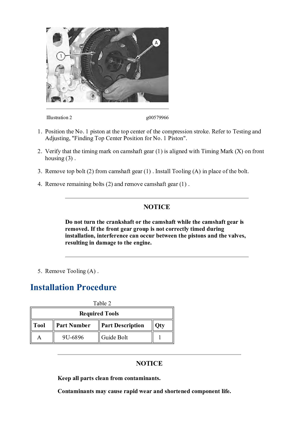
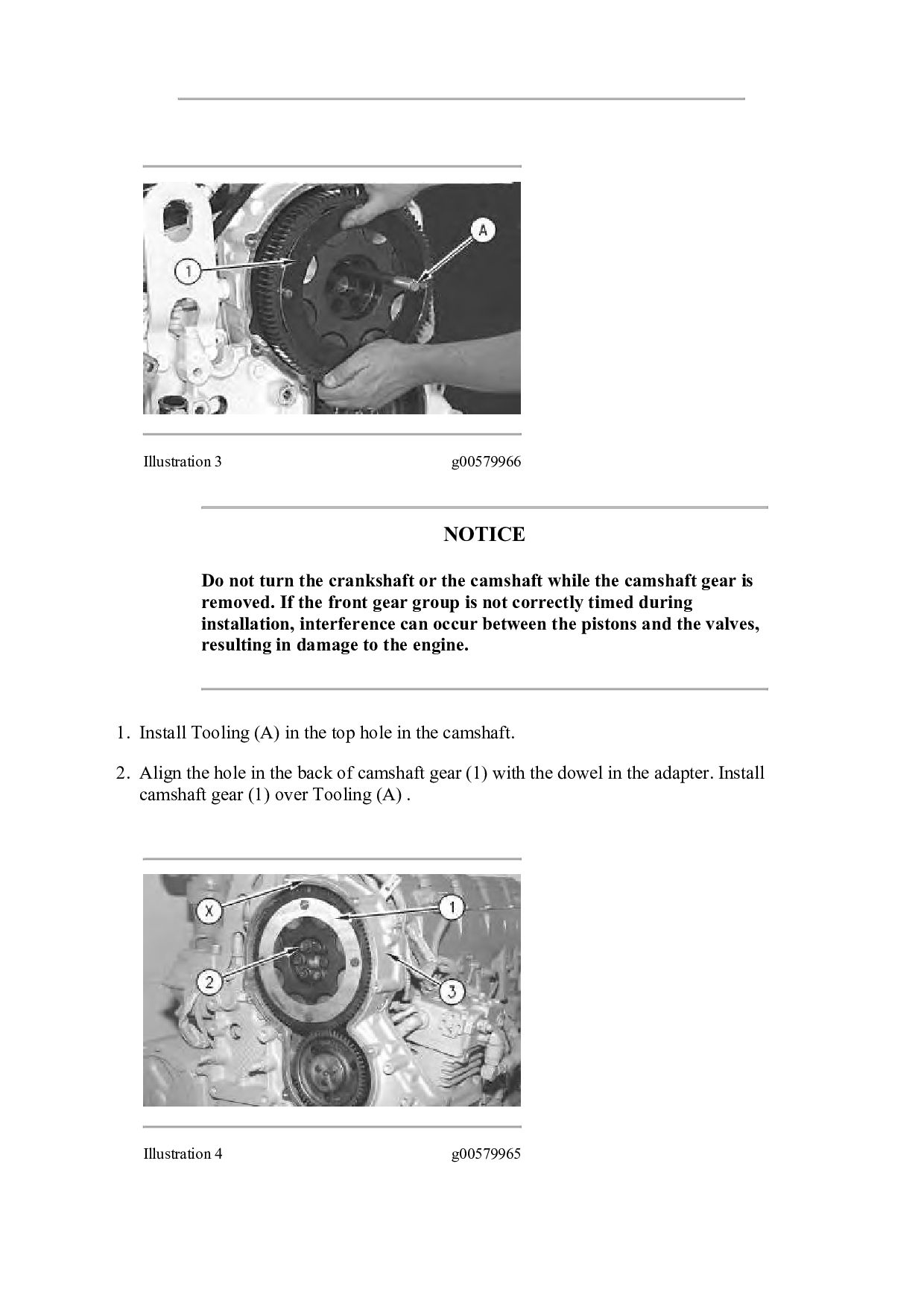
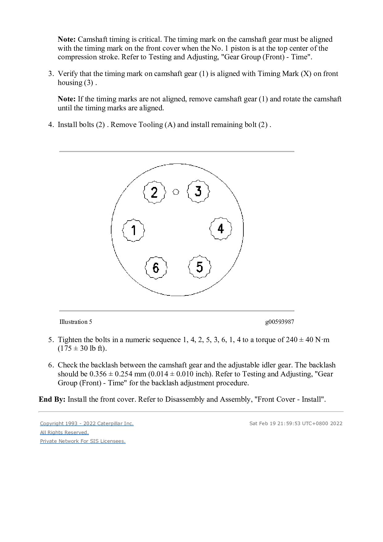
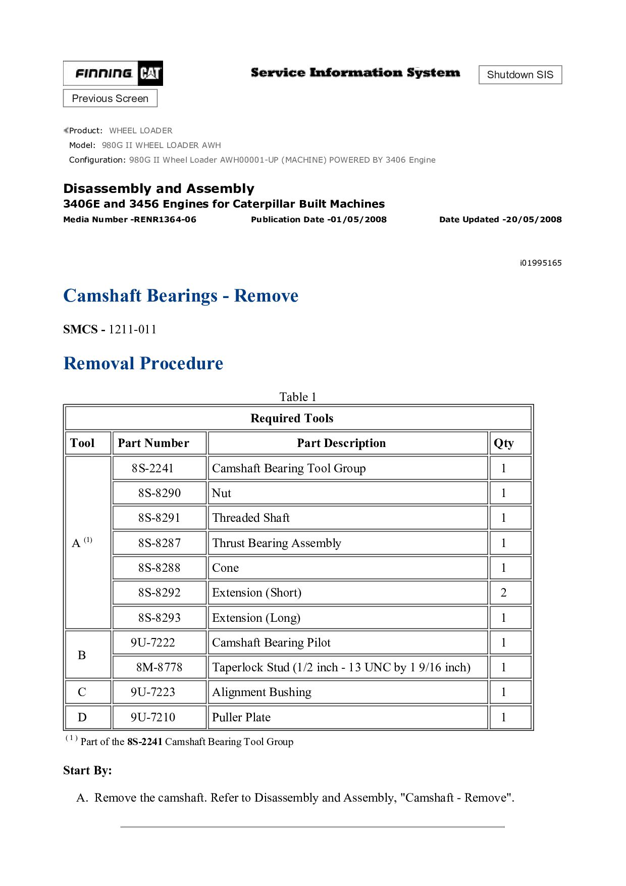
    camshaft gear must be aligned with the timing mark on the front cover when the No. 1 piston is at the top center of the compression stroke. Refer to Testing and Adjusting, "Gear Group (Front) - Time". 3. Verify that the timing mark on camshaft gear (1) is aligned with Timing Mark (X) on front housing (3) . Note: If the timing marks are not aligned, remove camshaft gear (1) and rotate the camshaft until the timing marks are aligned. 4. Install bolts (2) . Remove Tooling (A) and install remaining bolt (2) . Illustration 5 g00593987 5. Tighten the bolts in a numeric sequence 1, 4, 2, 5, 3, 6, 1, 4 to a torque of 240 ± 40 N·m (175 ± 30 lb ft). 6. Check the backlash between the camshaft gear and the adjustable idler gear. The backlash should be 0.356 ± 0.254 mm (0.014 ± 0.010 inch). Refer to Testing and Adjusting, "Gear Group (Front) - Time" for the backlash adjustment procedure. End By: Install the front cover. Refer to Disassembly and Assembly, "Front Cover - Install". Copyright 1993 - 2022 Caterpillar Inc. All Rights Reserved. Private Network For SIS Licensees. Sat Feb 19 21:59:53 UTC+0800 2022
  24. Shutdown SIS Previous Screen Product: WHEEL LOADER Model: 980G II

    WHEEL LOADER AWH Configuration: 980G II Wheel Loader AWH00001-UP (MACHINE) POWERED BY 3406 Engine Disassembly and Assembly 3406E and 3456 Engines for Caterpillar Built Machines Media Number -RENR1364-06 Publication Date -01/05/2008 Date Updated -20/05/2008 i01995165 Camshaft Bearings - Remove SMCS - 1211-011 Removal Procedure Table 1 Required Tools Tool Part Number Part Description Qty A (1) 8S-2241 Camshaft Bearing Tool Group 1 8S-8290 Nut 1 8S-8291 Threaded Shaft 1 8S-8287 Thrust Bearing Assembly 1 8S-8288 Cone 1 8S-8292 Extension (Short) 2 8S-8293 Extension (Long) 1 B 9U-7222 Camshaft Bearing Pilot 1 8M-8778 Taperlock Stud (1/2 inch - 13 UNC by 1 9/16 inch) 1 C 9U-7223 Alignment Bushing 1 D 9U-7210 Puller Plate 1 ( 1 ) Part of the 8S-2241 Camshaft Bearing Tool Group Start By: A. Remove the camshaft. Refer to Disassembly and Assembly, "Camshaft - Remove".
  25. NOTICE Keep all parts clean from contaminants. Contaminants may cause

    rapid wear and shortened component life. Illustration 1 g01005315 1. Remove bolts (1) from rear cover (2). Inspect the O-ring seal and replace the O-ring seal if the O-ring seal is worn or damaged.
  26. Illustration 2 g01034895 2. Remove the No. 7 camshaft bearing

    (rear). Work from the rear of the engine to the front of the engine. 3. Install the small end of Tooling (B) in the camshaft bearing. 4. Position Tooling (D) on Tooling (A). Install Tooling (A) on Tooling (B) . Note: Tooling (D) is installed on the outside of the cylinder head. Tooling (D) is required in order to remove the No. 7 camshaft bearing from the cylinder head. 5. Use Tooling (A) to remove camshaft bearing (3) from the cylinder head. 6. Remove Tooling (B) from Tooling (A) and remove the camshaft bearing. 7. Repeat Step 3 through Step 6 in order to remove the remaining camshaft bearings. Work from the rear of the engine to the front of the engine. Copyright 1993 - 2022 Caterpillar Inc. All Rights Reserved. Private Network For SIS Licensees. Sat Feb 19 22:00:49 UTC+0800 2022
  27. Shutdown SIS Previous Screen Product: WHEEL LOADER Model: 980G II

    WHEEL LOADER AWH Configuration: 980G II Wheel Loader AWH00001-UP (MACHINE) POWERED BY 3406 Engine Disassembly and Assembly 3406E and 3456 Engines for Caterpillar Built Machines Media Number -RENR1364-06 Publication Date -01/05/2008 Date Updated -20/05/2008 i01995166 Camshaft Bearings - Install SMCS - 1211-012 Installation Procedure Table 1 Required Tools Tool Part Number Part Description Qty A (1) 8S-2241 Camshaft Bearing Tool Group 1 8S-8290 Nut 1 8S-8291 Threaded Shaft 1 8S-8287 Thrust Bearing Assembly 1 8S-8288 Cone 1 8S-8292 Extension (Short) 2 8S-8293 Extension (Long) 1 B 9U-7222 Camshaft Bearing Pilot 1 8M-8778 Taperlock Stud (1/2 inch - 13 UNC by 1 9/16 inch) 1 C 9U-7223 Alignment Bushing 1 D 9U-7210 Puller Plate 1 E 9U-7213 Backup Plate 1 0S-1621 Bolt (1/2 inch - 13 UNC by 1 inch) 1 F 9U-7214 Spacer Plate 1 ( 1 ) Part of the 8S-2241 Camshaft Bearing Tool Group
  28. NOTICE Keep all parts clean from contaminants. Contaminants may cause

    rapid wear and shortened component life. Note: Ensure that the inside of the cylinder head is clean. Inspect the camshaft bore for metal burrs. Put a thin film of clean engine oil on the inside of the camshaft bearing bores and on each camshaft bearing prior to installation. Illustration 1 g01034920 1. Install the No. 7 camshaft bearing (rear), as follows: a. Insert the large end of Tooling (B) into the No. 7 camshaft bore. Position camshaft bearing (3) on Tooling (B) . b. Position Tooling (D) on Tooling (A). Install Tooling (A) in Tooling (B) . c. Position camshaft bearing (3) on Tooling (B). Install Tooling (E) on Tooling (B) . Note: Refer to Specifications, "Cylinder Head" for appropriate information for the orientation of the camshaft bearings in the cylinder head. d. Use Tooling (A) in order to pull camshaft bearing (3) into the camshaft bore. Note: When the chamfer of Tooling (E) contacts the face of the camshaft bore, the camshaft bearing is properly installed.
  29. Please write to us. Our email: [email protected] Please go to

    the homepage to get the full manual, or other brand PDF manuals. Home Site: aservicemanualpdf.com
  30. Thank you very much for your reading. Please Click Here.

    Then Get COMPLETE MANUAL. NO WAITING NOTE: If there is no response to click on the link above, please download the PDF document first and then click on it.
  31. e. Remove Tooling (E) from Tooling (B). Remove Tooling (A)

    from Tooling (B). Remove Tooling (B) from the cylinder head. Illustration 2 g01034921 2. Install the No. 6 through No. 2 camshaft bearings, as follows: a. Insert the large end of Tooling (B) into the camshaft bore. Note: Use Tooling (C) to align Tooling (A) and Tooling (B) with the camshaft bearing bores. Install Tooling (C) in the inside diameter of any installed camshaft bearing between Tooling (A) and Tooling (B) . b. Install Tooling (A) in Tooling (B). Position camshaft bearing (3) on Tooling (B). Install Tooling (E) on Tooling (B) . Note: Refer to Specifications, "Cylinder Head" for appropriate information for the location and the orientation of the camshaft bearings in the cylinder head. c. Use Tooling (A) in order to pull camshaft bearing (3) into the camshaft bore. Note: When the chamfer of Tooling (E) contacts the face of the camshaft bore, the camshaft bearing is properly installed. d. Remove Tooling (E) from Tooling (B). Remove Tooling (A) from Tooling (B) . e. Remove Tooling (B) and Tooling (C) from the cylinder head. 3. Repeat Step 2 in order to install the No. 6 through No. 2 camshaft bearings.
  32. Illustration 3 g01034922 4. Install the No. 1 camshaft bearing

    (front), as follows: a. Insert the large end of Tooling (B) into the No. 1 camshaft bore. Assemble Tooling (A) and Tooling (C) on Tooling (B) . b. Position camshaft bearing (3) on Tooling (B). Install Tooling (E) and Tooling (F) on Tooling (B) . Note: Refer to Specifications, "Cylinder Head" for appropriate information for the location and the orientation of the camshaft bearings in the cylinder head. Note: Tooling (F) is used to seat the No. 1 camshaft bearing to the correct depth in the camshaft bore. c. Use Tooling (A) in order to pull the No. 1 camshaft bearing into the No. 1 camshaft bore. When the chamfer of Tooling (E) contacts the face of the camshaft bore, the camshaft bearing is properly installed. d. Remove Tooling (E) and Tooling (F) from Tooling (B). Remove Tooling (A) from Tooling (B) . e. Remove Tooling (B) and Tooling (C) from the cylinder head.
  33. Illustration 4 g01005315 5. Inspect the O-ring seal. Replace the

    O-ring seal if the seal is worn or damaged. Position rear cover (2). Install bolts (1). Tighten the bolts to a torque of 13 ± 3 N·m (10 ± 2 lb ft). End By: Install the camshaft. Refer to Disassembly and Assembly, "Camshaft - Install". Copyright 1993 - 2022 Caterpillar Inc. All Rights Reserved. Private Network For SIS Licensees. Sat Feb 19 22:01:45 UTC+0800 2022
  34. https://www.aservicemanualpdf.com/ My Dear Friend! Thank you very much for visiting.

    Full manual if required, please enter the following URL into your browser. https://www.aservicemanualpdf.com/