Upgrade to Pro — share decks privately, control downloads, hide ads and more …

Controller Design for Symbolic Input-Output Sys...

Sponsored · Your Podcast. Everywhere. Effortlessly. Share. Educate. Inspire. Entertain. You do you. We'll handle the rest.
Avatar for konakalab konakalab
August 27, 2026

Controller Design for Symbolic Input-Output Systems Using Feedforward Neural Networks

This was presented at 23rd IFAC World Congress (https://www.ifac2026.org/fairDash.do). Movies are not included due to the specifications of speakerdeck.

Avatar for konakalab

konakalab

August 27, 2026

More Decks by konakalab

Other Decks in Science

Transcript

  1. Controller Design for Symbolic Input-Output Systems Using Feedforward Neural Networks

    Kohtaroh HIBINO∗, Eiji KONAKA (Meijo University, Japan)
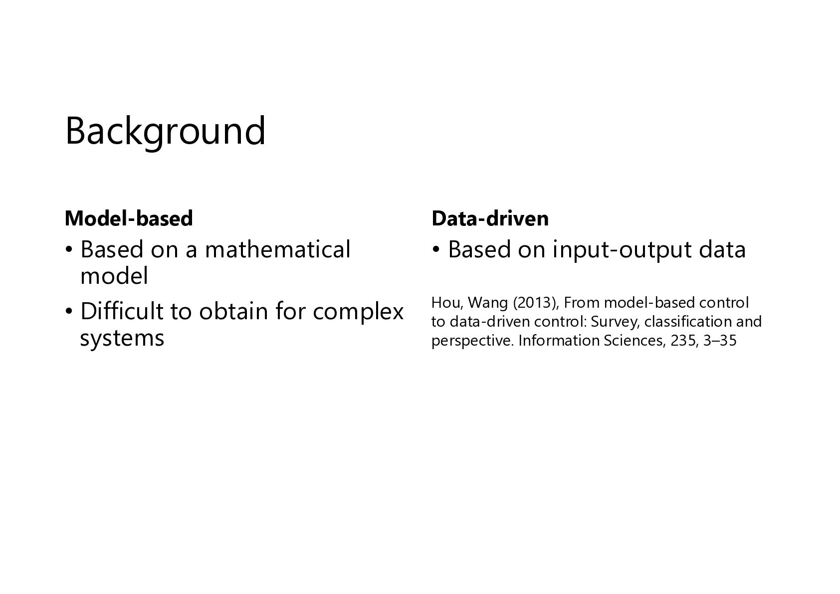
  2. Background Model-based Data-driven • Based on a mathematical model •

    Difficult to obtain for complex systems • Based on input-output data Hou, Wang (2013), From model-based control to data-driven control: Survey, classification and perspective. Information Sciences, 235, 3–35
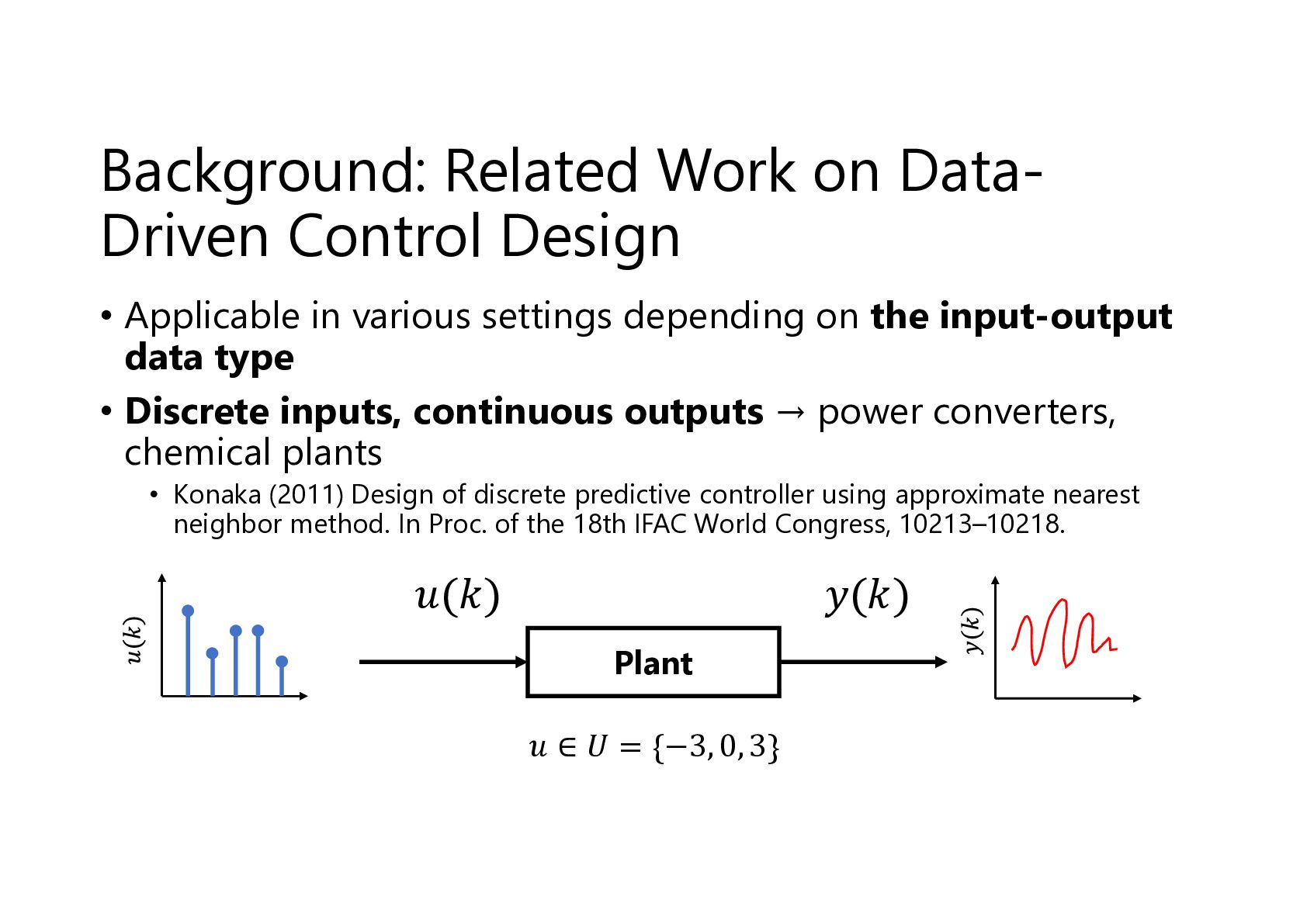
  3. Background: Related Work on DataDriven Control Design • Applicable in

    various settings depending on the input-output data type • Discrete inputs, continuous outputs → power converters, chemical plants • Konaka (2011) Design of discrete predictive controller using approximate nearest neighbor method. In Proc. of the 18th IFAC World Congress, 10213–10218. 𝑢(𝑘) 𝑦(𝑘) Plant 𝑢 ∈ 𝑈 = {−3, 0, 3}
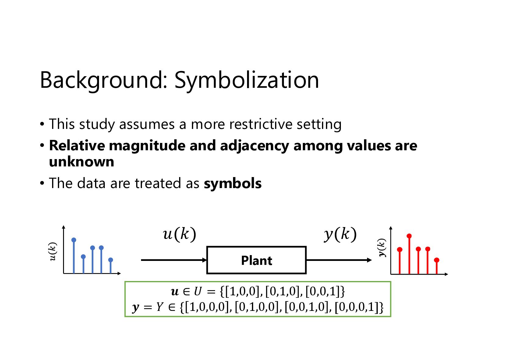
  4. Background: Symbolization • This study assumes a more restrictive setting

    • Relative magnitude and adjacency among values are unknown • The data are treated as symbols 𝑢(𝑘) 𝑦(𝑘) Plant 𝒖 ∈ 𝑈 = 1,0,0 , 0,1,0 , 0,0,1 𝒚 = 𝑌 ∈ { 1,0,0,0 , 0,1,0,0 , 0,0,1,0 , [0,0,0,1]}
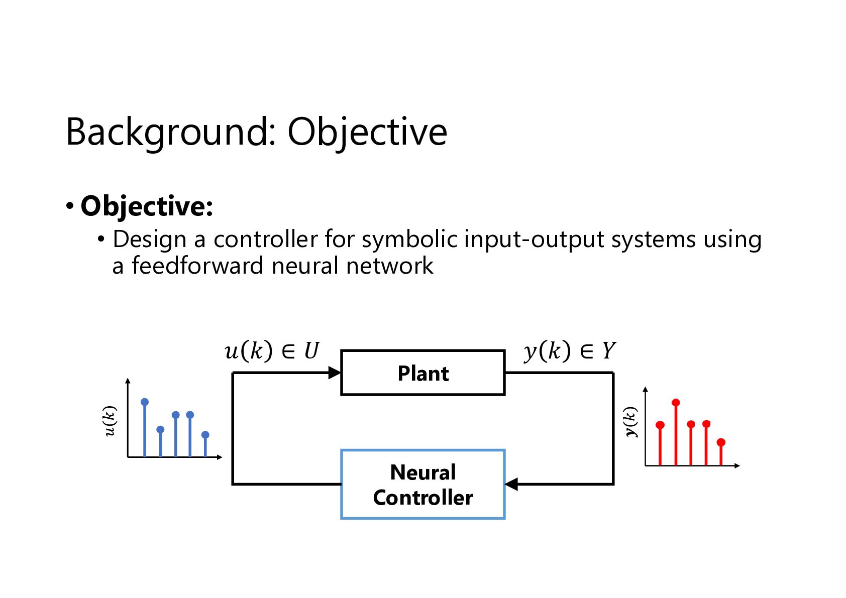
  5. Background: Objective • Objective: • Design a controller for symbolic

    input-output systems using a feedforward neural network 𝑢 𝑘 ∈𝑈 Plant Neural Controller 𝑦 𝑘 ∈𝑌
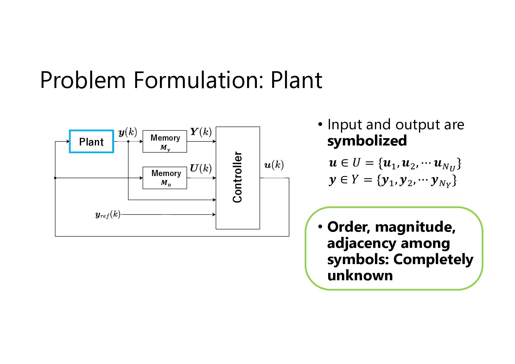
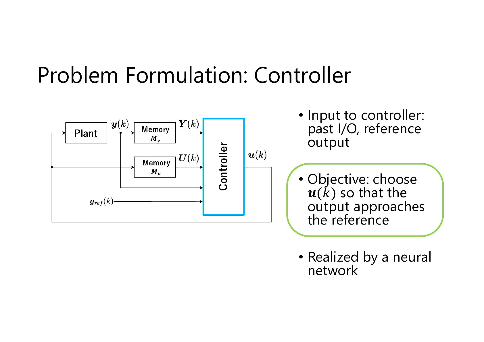
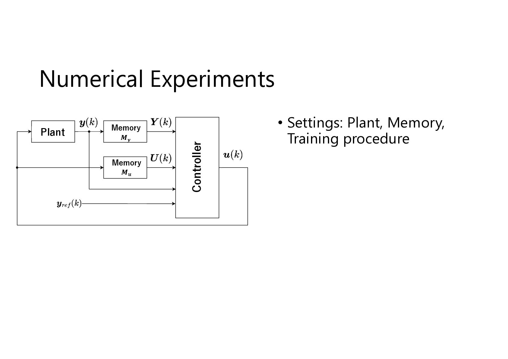
  6. Problem Formulation: Plant Memory 𝑴𝒚 Memory 𝑴𝒖 Controller Plant •

    Input and output are symbolized 𝒖 ∈ 𝑈 = {𝒖 , 𝒖 , ⋯ 𝒖 } 𝒚 ∈ 𝑌 = {𝒚 , 𝒚 , ⋯ 𝒚 } • Order, magnitude, adjacency among symbols: Completely unknown
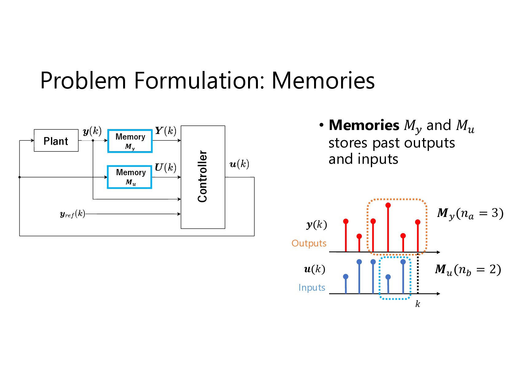
  7. Plant Memory 𝑴𝒚 Memory 𝑴𝒖 Controller Problem Formulation: Memories •

    Memories 𝑀 and 𝑀 stores past outputs and inputs 𝑴 (𝑛 = 3) 𝒚(𝑘) Outputs 𝑴 (𝑛 = 2) 𝒖(𝑘) Inputs 𝑘
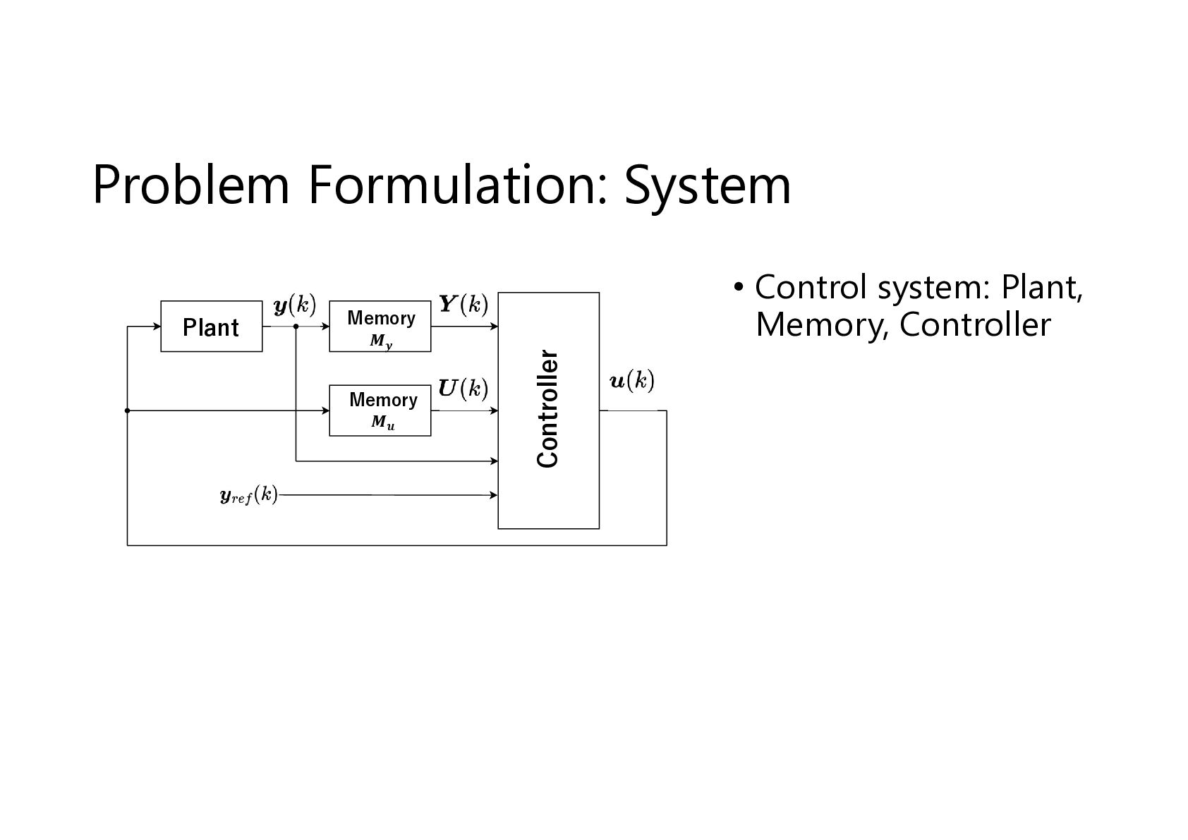
  8. Plant Memory 𝑴𝒚 Memory 𝑴𝒖 Controller Problem Formulation: Controller •

    Input to controller: past I/O, reference output • Objective: choose 𝒖(𝑘) so that the output approaches the reference • Realized by a neural network
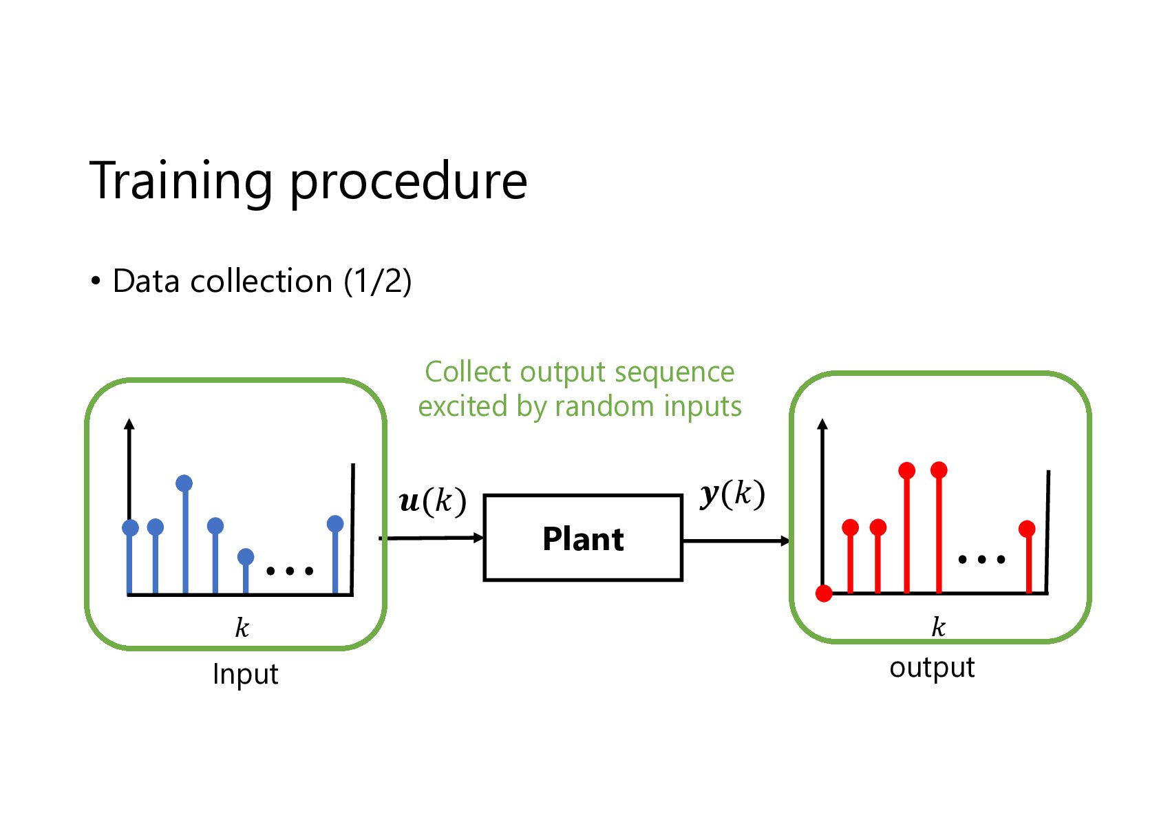
  9. Training procedure • Data collection (1/2) Collect output sequence excited

    by random inputs 𝒖(𝑘) 𝑘 Input 𝒚(𝑘) Plant 𝑘 output
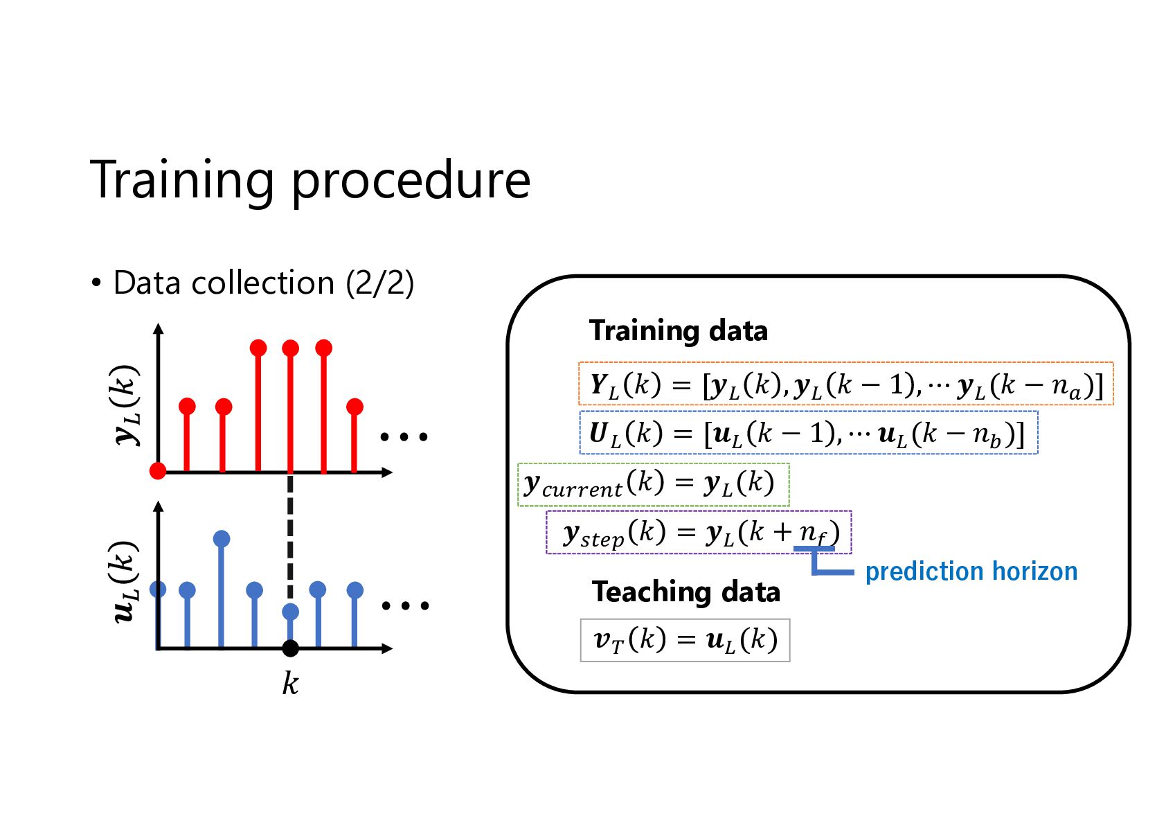
  10. Training procedure • Data collection (2/2) Training data 𝒀 𝑘

    = [𝒚 𝑘 , 𝒚 𝑘 − 1 , ⋯ 𝒚 (𝑘 − 𝑛 )] 𝑼 𝑘 = [𝒖 𝑘 − 1 , ⋯ 𝒖 (𝑘 − 𝑛 )] 𝒚 𝑘 = 𝒚 (𝑘) 𝒚 𝑘 = 𝒚 (𝑘 + 𝑛 ) Teaching data 𝒗 𝑘 = 𝒖 (𝑘) 𝑘 prediction horizon
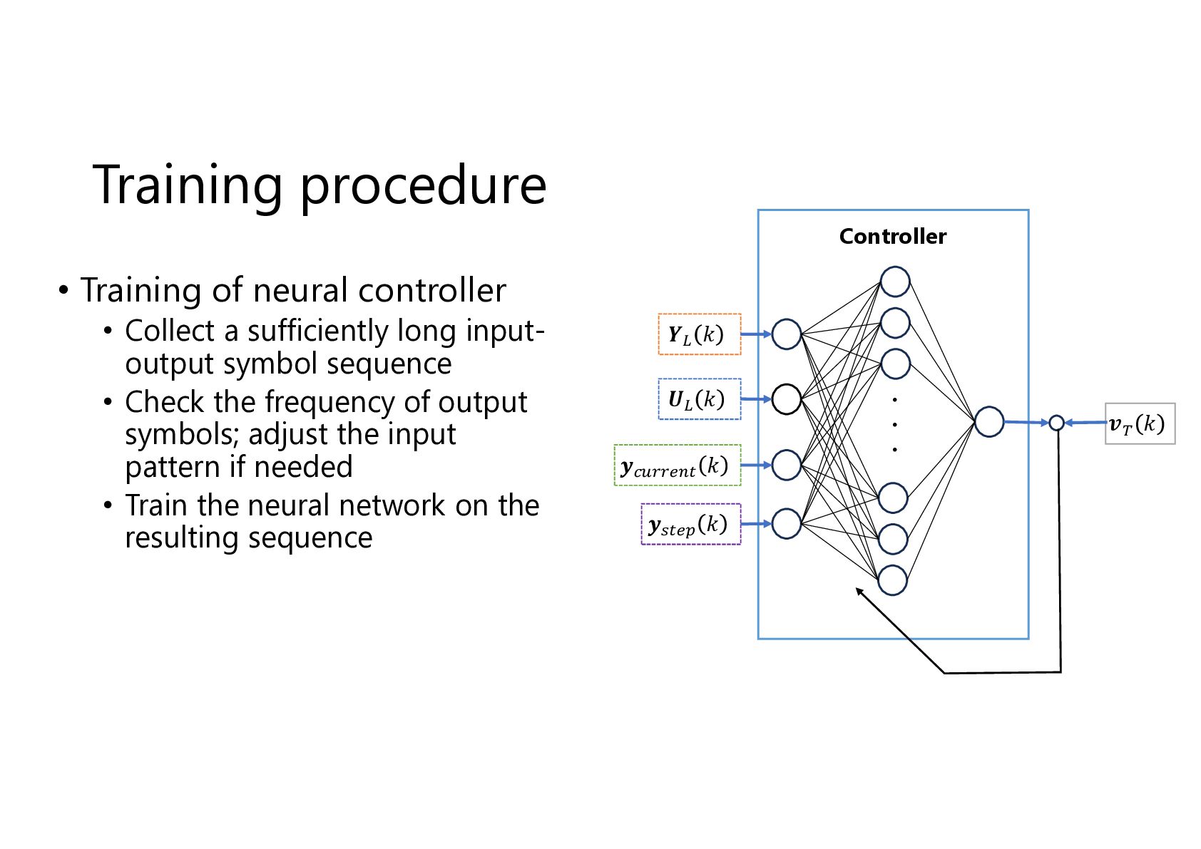
  11. Training procedure Controller • Training of neural controller • Collect

    a sufficiently long inputoutput symbol sequence • Check the frequency of output symbols; adjust the input pattern if needed • Train the neural network on the resulting sequence 𝒀 𝑘 𝑼 𝑘 𝒚 𝑘 𝒚 𝑘 ・ ・ ・ 𝒗 𝑘
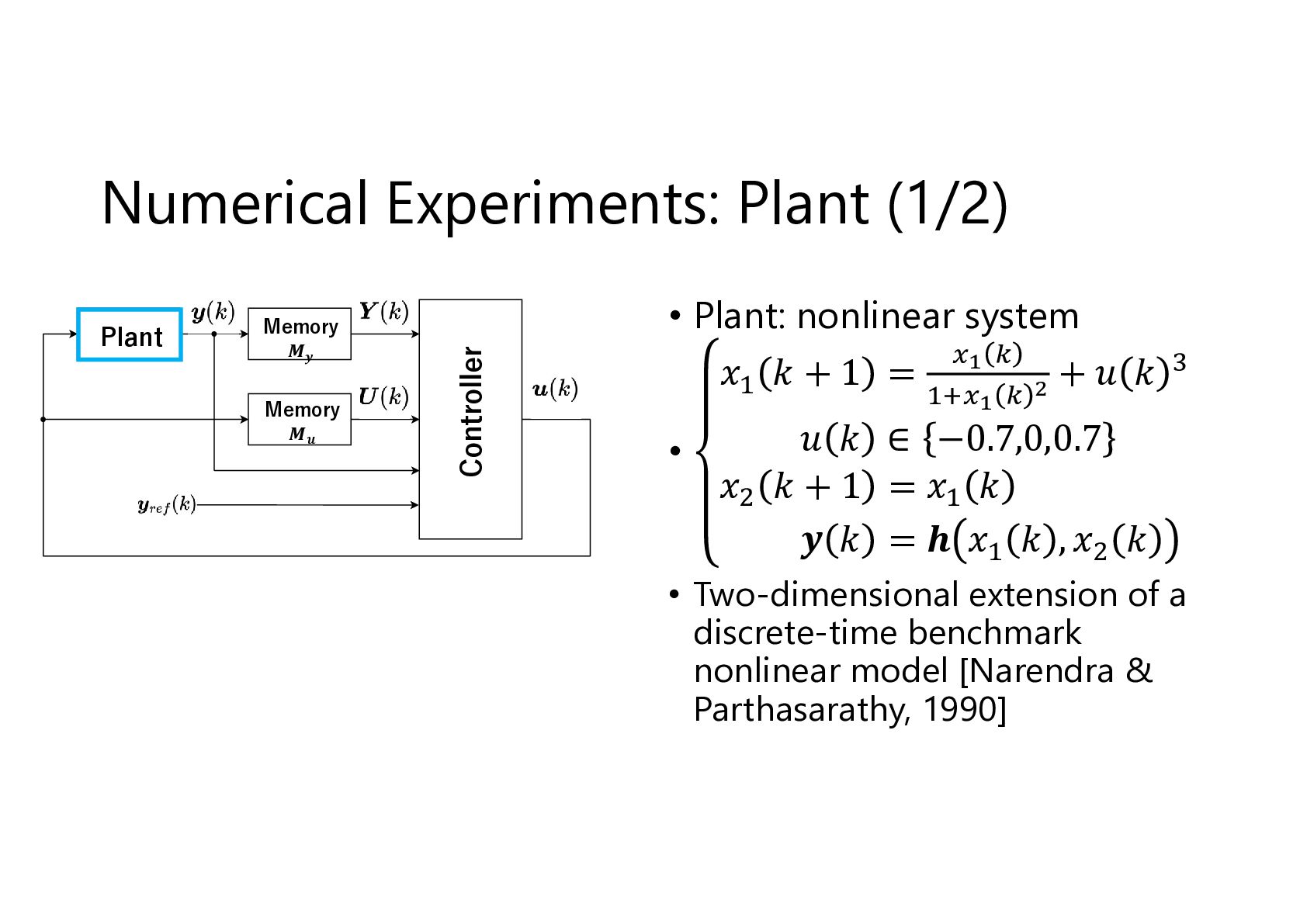
  12. Plant Memory 𝑴𝒚 Memory 𝑴𝒖 Controller Numerical Experiments: Plant (1/2)

    • Plant: nonlinear system 𝑥 𝑘+1 = +𝑢 𝑘 • 𝑢 𝑘 ∈ −0.7,0,0.7 𝑥 𝑘+1 =𝑥 𝑘 𝒚 𝑘 = 𝒉 𝑥 𝑘 ,𝑥 𝑘 • Two-dimensional extension of a discrete-time benchmark nonlinear model [Narendra & Parthasarathy, 1990]
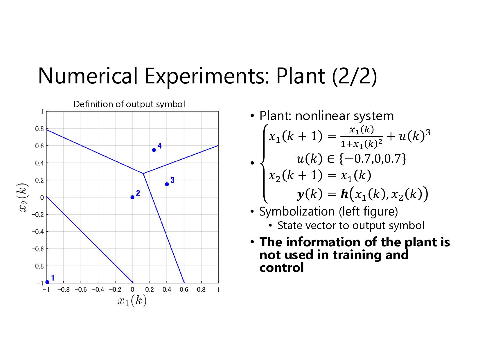
  13. Numerical Experiments: Plant (2/2) Definition of output symbol • Plant:

    nonlinear system 𝑥 𝑘+1 = • +𝑢 𝑘 𝑢 𝑘 ∈ −0.7,0,0.7 𝑥 𝑘+1 =𝑥 𝑘 𝒚 𝑘 = 𝒉 𝑥 𝑘 ,𝑥 𝑘 • Symbolization (left figure) • State vector to output symbol • The information of the plant is not used in training and control
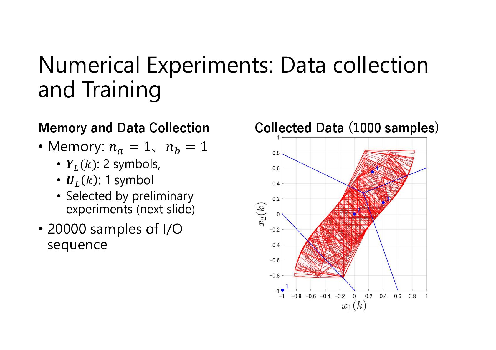
  14. Numerical Experiments: Data collection and Training Memory and Data Collection

    • Memory: 𝑛 = 1、𝑛 = 1 • 𝒀 (𝑘): 2 symbols, • 𝑼 𝑘 : 1 symbol • Selected by preliminary experiments (next slide) • 20000 samples of I/O sequence Collected Data (1000 samples)
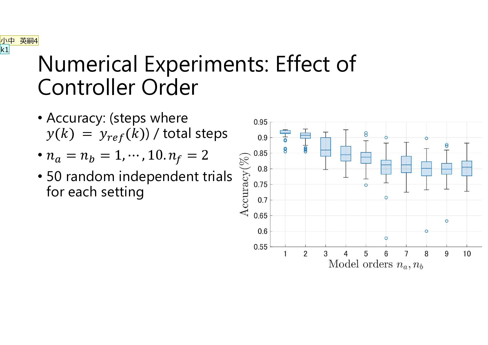
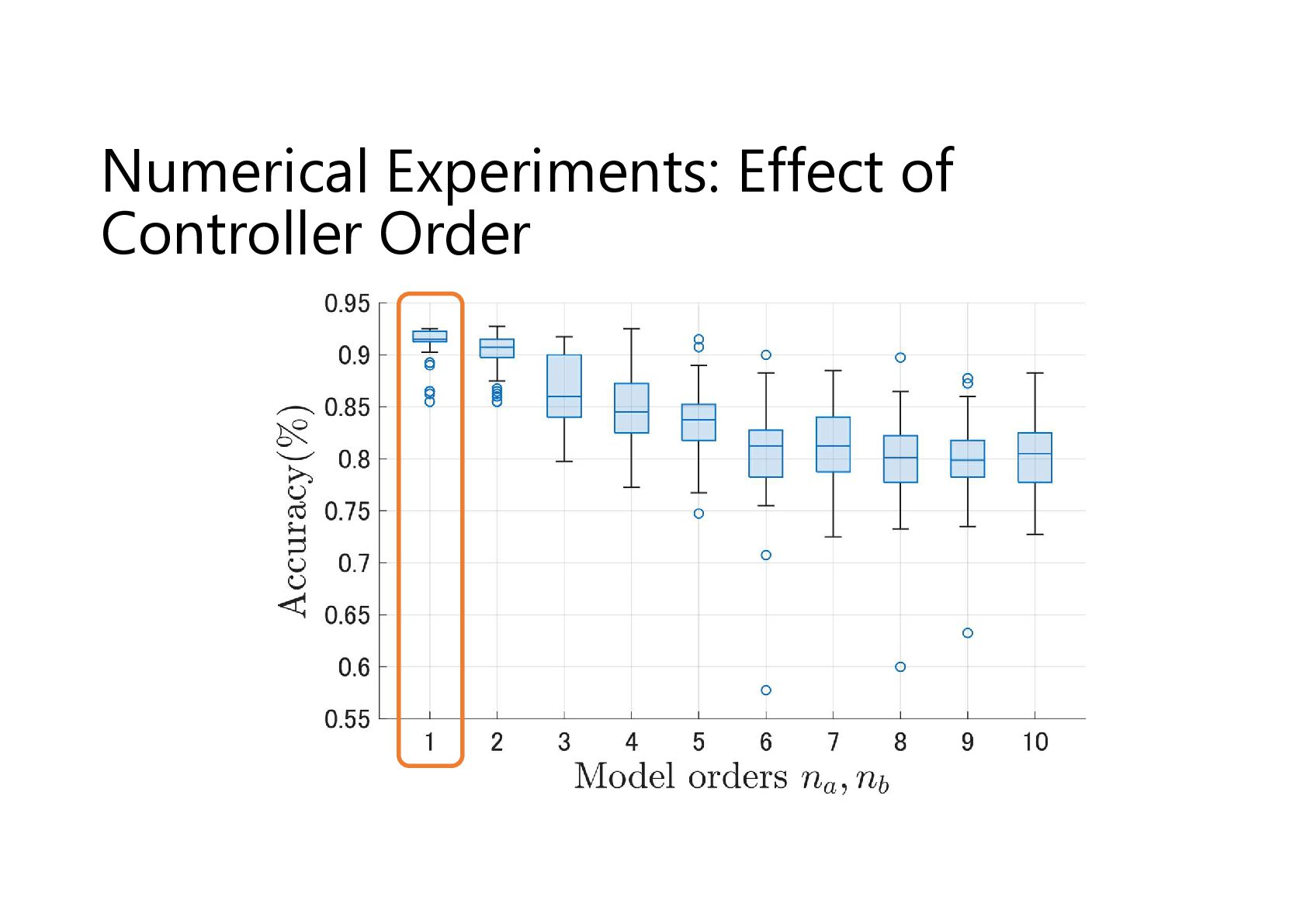
  15. 小中 英嗣4 k1 Numerical Experiments: Effect of Controller Order •

    Accuracy: (steps where 𝑦(𝑘) = 𝑦 (𝑘)) / total steps • 𝑛 = 𝑛 = 1, ⋯ , 10. 𝑛 = 2 • 50 random independent trials for each setting
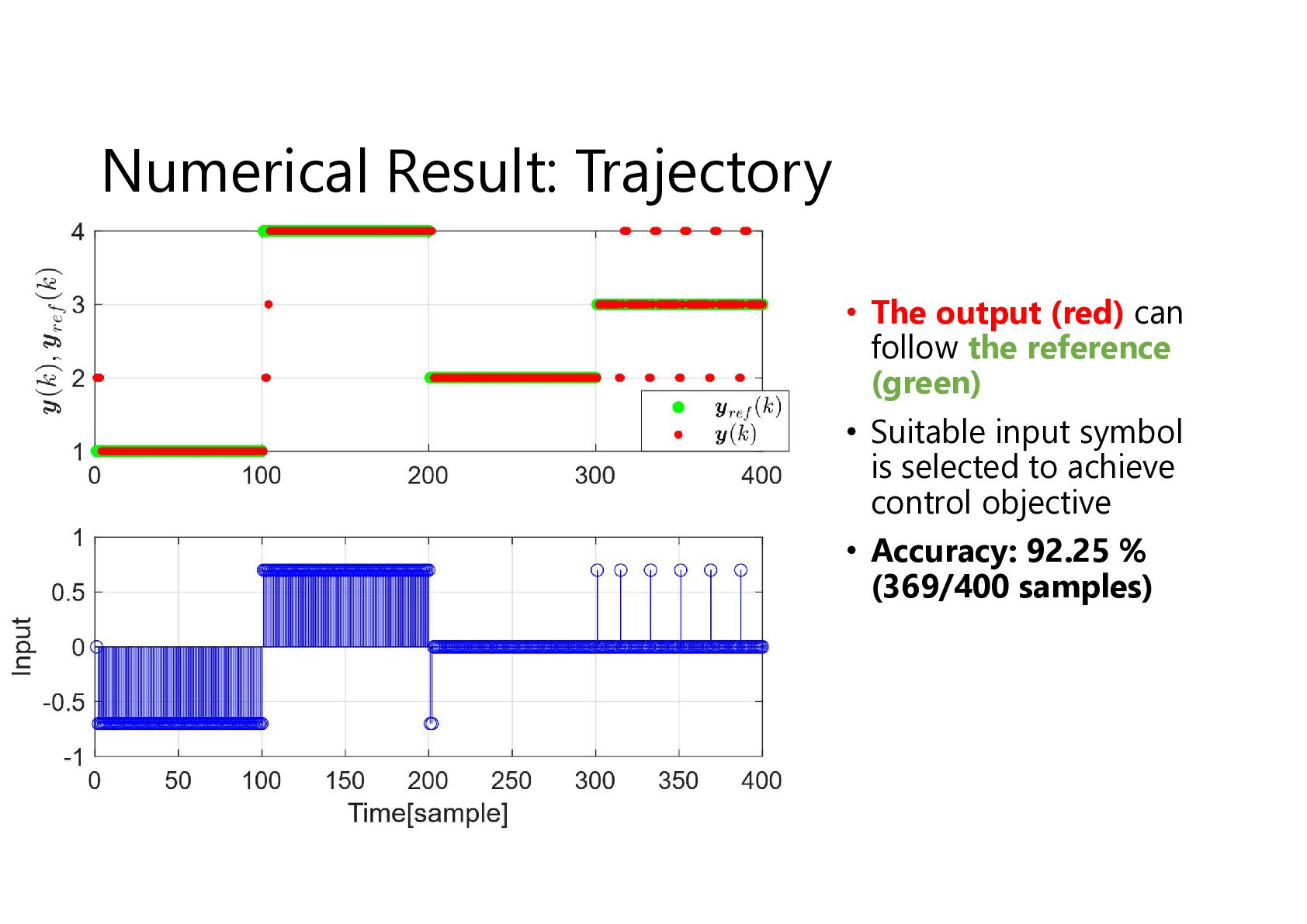
  16. Numerical Result: Trajectory • The output (red) can follow the

    reference (green) • Suitable input symbol is selected to achieve control objective • Accuracy: 92.25 % (369/400 samples)
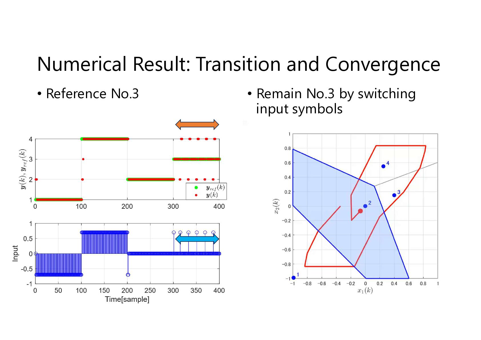
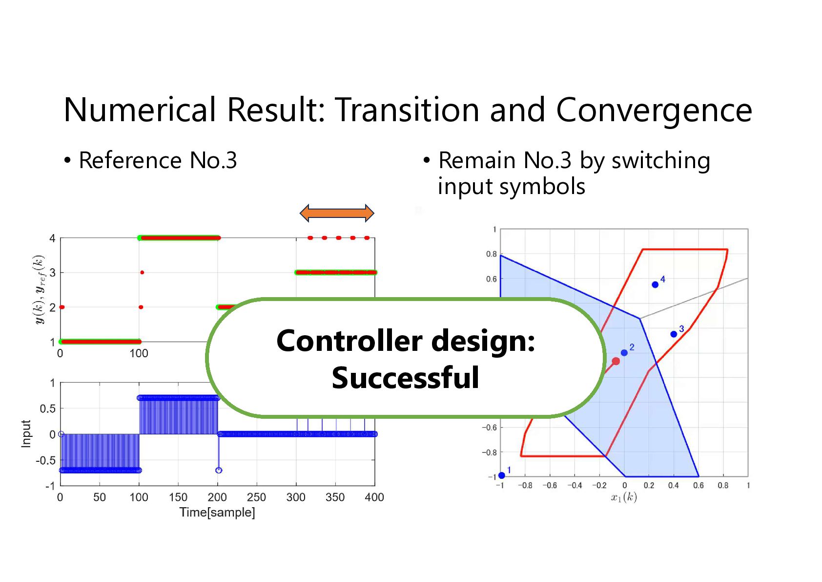
  17. Numerical Result: Transition and Convergence • Reference No.3 • Remain

    No.3 by switching input symbols Controller design: Successful
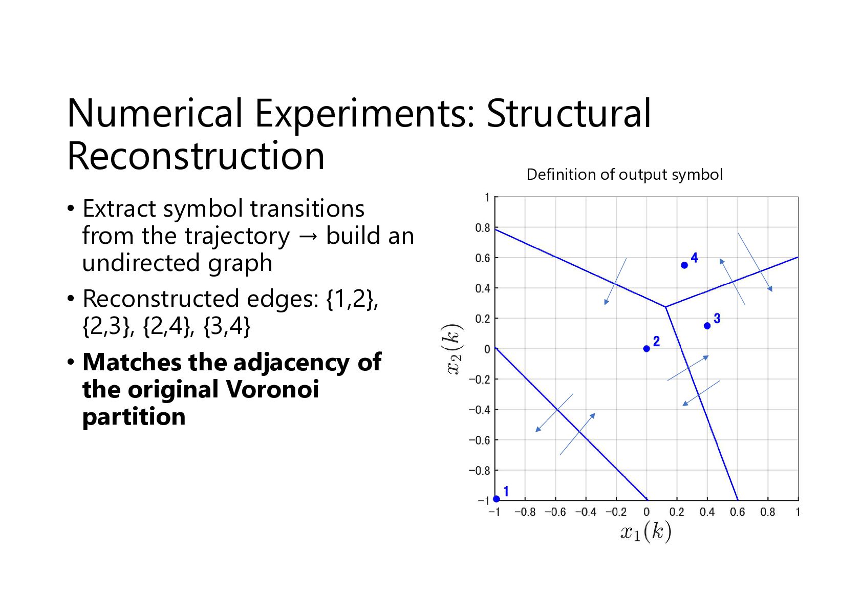
  18. Numerical Experiments: Structural Reconstruction Definition of output symbol • Extract

    symbol transitions from the trajectory → build an undirected graph • Reconstructed edges: {1,2}, {2,3}, {2,4}, {3,4} • Matches the adjacency of the original Voronoi partition
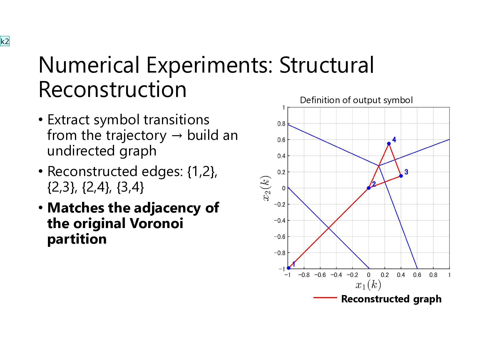
  19. k2 Numerical Experiments: Structural Reconstruction Definition of output symbol •

    Extract symbol transitions from the trajectory → build an undirected graph • Reconstructed edges: {1,2}, {2,3}, {2,4}, {3,4} • Matches the adjacency of the original Voronoi partition Reconstructed graph
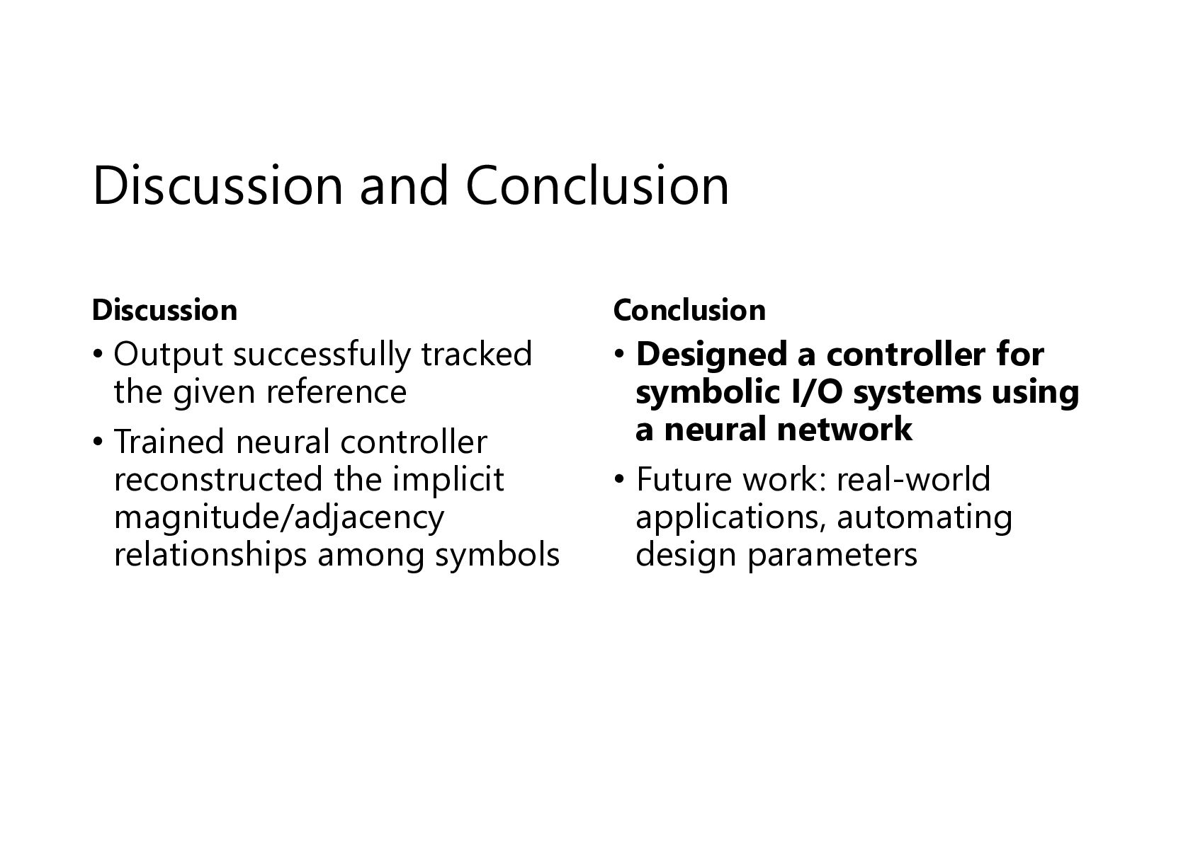
  20. Discussion and Conclusion Discussion Conclusion • Output successfully tracked the

    given reference • Trained neural controller reconstructed the implicit magnitude/adjacency relationships among symbols • Designed a controller for symbolic I/O systems using a neural network • Future work: real-world applications, automating design parameters