Share
Embed
Controlling a Laser with the Raspberry Pi
Lukas
July 06, 2018
Transcript
28 slides
-
Controlling a Laser with the Raspberry Pi M3 Techtalk #96
2018/7/6 M3 Inc., Lukas Prasuhn -
About Me - Software Engineer @ M3 - 12 years
in Japan from Germany - Github: https://github.com/lukasjapan - Tech I like - Raspberry Pi - Kotlin/Java - Ruby - ... - Creator of “bt-speaker” - Bluetooth speaker Daemon for Raspberry Pi -
Index - Mission - Hardware - Raspberry Pi W Zero
- Laser & Galvos - Power LEDs - Power supply - GPIO & Homebrew circuits - Software - Demo - Ilda-tools - Demo - TODO -
Mission - Control a laser with the Raspberry Pi -
Draw pictures - Principle can also be applied to laser cutting, laser engraving, ... -
Raspberry Pi W Zero - The little brother in the
Raspberry Pi family - Bluetooth/WLAN - HDMI - MicroUSB - GPIO (General Purpose Input Output) -
Laser & Galvos - Principle - Visible light laser -
“Galvo Scanner” - Movable mirrors - One galvo controls one axis - 2D Projection with 2 signals -
Laser & Galvos - The real thing - Red laser
module from Akihabara - Galvos imported from China - Driver Board included - 2 signal input (-10V ~ +10V) - (I broke the control board in process) -
Power Supply - The Chinese Way - No manual! -
AC Input - 220V? - 110V? - Both? - DC Output - ±12V (-12V, 0V, 12V) - (maybe) -
Power Supply - My Way - 2 separate 12V inputs
- DC Plug - Connect 12V of Input A to Input B - Connected inside module - Do not use same battery! - … if battery has multiple outputs -
Power supply - Application +12V | 24V 0V | 12V
+12V | 0V 5V - Raspberry Pi Power LEDs 3V - Laser Module ±10V Laser Signal 12V-5V DC-DC Converter 3V Regulator ±12V Galvos -
GPIO - Generate Signals - General Purpose Input Output -
0 or 3.3 V Output - 2 Pins with 0~3.3V Output - PWM -
GPIO - Sound over GPIO - Raspberry Pi plays audio
via PWM - lower quality - cheap and dirty - Connecting PWM GPIO to soundcard - only way to output sound when using Pi W Zero - Play audio - interfaced data stream - timing (in kernel) - effectively maps sound samples to 0 ~ 3.3V - 2 channels - no low pass filter (condensators) - which is good for this application -
Homebrew Circuit - Raising the signal - galvo signal range
is 20V - otherwise image is tiny - 0 ~ 3.3V → 2V ~ 22V (±10V) - Signal Shifting + Amplifying - Math/Programming - out = in * 6 + 2 - Circuit - OPAmp → - clamped by power voltage -
Homebrew Circuit - Raising the signal - galvo signal range
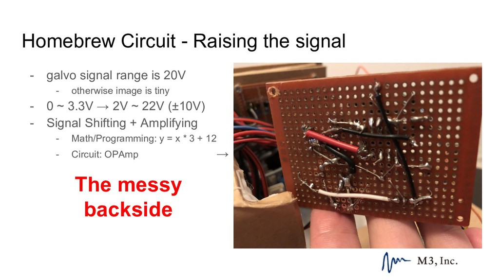
is 20V - otherwise image is tiny - 0 ~ 3.3V → 2V ~ 22V (±10V) - Signal Shifting + Amplifying - Math/Programming: y = x * 3 + 12 - Circuit: OPAmp → The messy backside -
Homebrew Circuit - LED Controller - Controllable via 3.3 V
signal - 3 channel RGB - additional 24V output - Parts - Transistors for LEDs - Power MOSFET for 24V output - ... -
Demo Setup - SSH Port forwarding - Over my public
VPN - in Germany - This was the easiest setup - what a modern world we live in :) -
Demo Setup - SSH Port forwarding - Over my public
VPN - in Germany - This was the easiest setup - what a modern world we live in :) 2 m 18652 km (round trip) -
Demo 1 - LEDs & Laser module - LED light
blinking - Switch on Laser -
Ilda-tools - Ilda - International Laser Display Association - .ild
- laser display (video) format - frames - points in each frame - big endian -
Ilda-tools - Library to process .ild files - https://github.com/lukasjapan/ilda-tools -
Command line centric - Made with linux philosophy in mind - Do one thing but do it good - C++ - Work in progress -
Ilda-tools - Alternative: Openlase - https://github.com/marcan/openlase - Jack (sound daemon)
centric - partly closed source - Python / C, C++ -
Demo 3 - ilda-wav - Convert .ild files to .wav
files - adjust pps - adjust play speed - adjust channels - ... -
Demo 4 - svg to ild - convert .svg files
(vector graphics) to .ild files - used openlase svg2ild.py implementation - soon in ilda-tools -
TODO - ilda-tools - Audio to ilda (visualizer) - Video
(contours) to ilda - OpenCV? - Emulator (GameBoy) to ilda - possible? - Blanking - Buy 2.1 channel external sound card? - Try to separately control over GPIO?