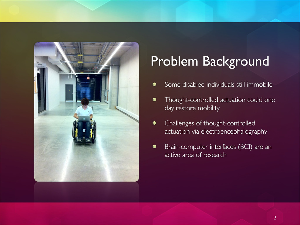
one day restore mobility Challenges of thought-controlled actuation via electroencephalography Brain-computer interfaces (BCI) are an active area of research 2
training of machine learning algorithm Online classification of brain wave signals passed to microcontrollers Incoming signal processed and corresponding control signals generated Motor drives execute motion through drivetrain Trajectory corresponding to user trained brain wave pattern is executed Tracking achieved via closed loop control with sensory feedback 3
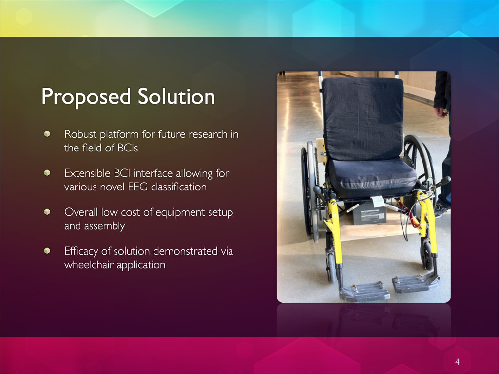
of BCIs Extensible BCI interface allowing for various novel EEG classification Overall low cost of equipment setup and assembly Efficacy of solution demonstrated via wheelchair application 4
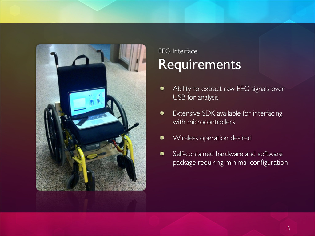
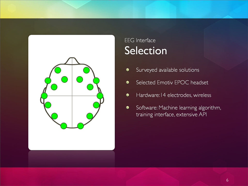
USB for analysis Extensive SDK available for interfacing with microcontrollers Wireless operation desired Self-contained hardware and software package requiring minimal configuration 5
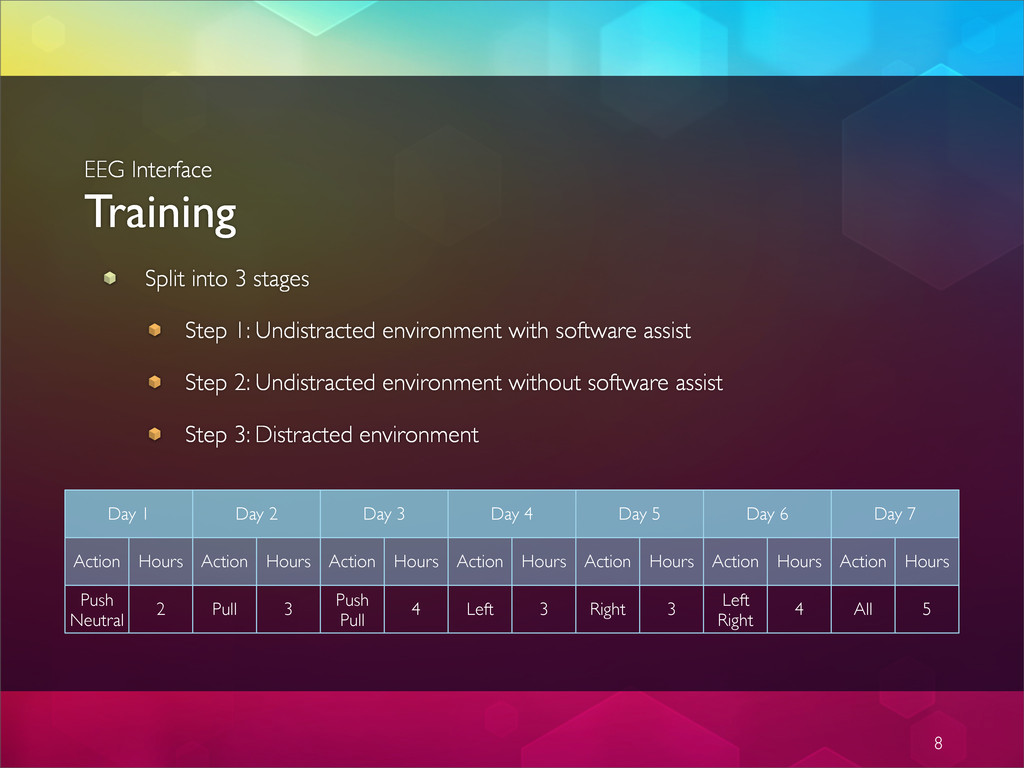
environment with software assist Step 2: Undistracted environment without software assist Step 3: Distracted environment 8 Day 1 Day 1 Day 2 Day 2 Day 3 Day 3 Day 4 Day 4 Day 5 Day 5 Day 6 Day 6 Day 7 Day 7 Action Hours Action Hours Action Hours Action Hours Action Hours Action Hours Action Hours Push Neutral 2 Pull 3 Push Pull 4 Left 3 Right 3 Left Right 4 All 5
train according to schedule Completed offline and user profile stored for future use in online classification 9 Increasing the number of concurrent actions increases the difficulty in maintaining conscious control over the Cognitiv detection results. Almost all new users readily gain control over a single action quite quickly. Learning to control multiple actions typically requires practice and becomes progressively harder as additional actions are added. Although Emotiv Control Panel allows a user to select up to 4 actions at a time, it is important that each user masters the use of the Cognitiv detection one action at a time, only increasing the number of concurrent actions after he has first gained confidence and accuracy with a lower number of actions. Figure 11 Cognitiv Suite Panel 3.5.2 Understanding the Cognitiv Panel Display The Cognitiv Suite panel uses a virtual 3D cube to display an animated representation of the Cognitiv detection output. This 3D cube is also used to assist the user in visualizing the intended action during the training process. The Power gauge to the left of the 3D display is an indicator of the “action power”, or relative certainty that the user is consciously visualizing the current action. The default tab on the Cognitiv panel is the Action tab. This tab displays information about the current state of the Cognitiv detection and allows the user to define the current set of actions. In order to enable the Cognitiv detection, each chosen action, plus the Neutral action, must first be trained. For more information about the training process please refer to
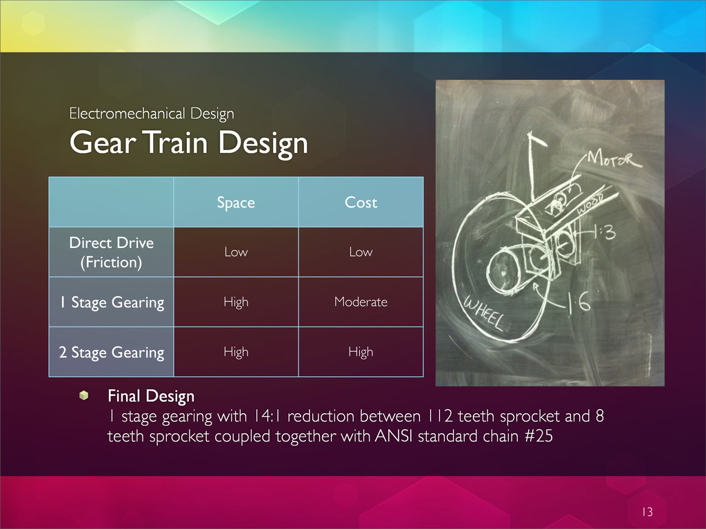
(Friction) 1 Stage Gearing 2 Stage Gearing Low Low High Moderate High High Final Design 1 stage gearing with 14:1 reduction between 112 teeth sprocket and 8 teeth sprocket coupled together with ANSI standard chain #25
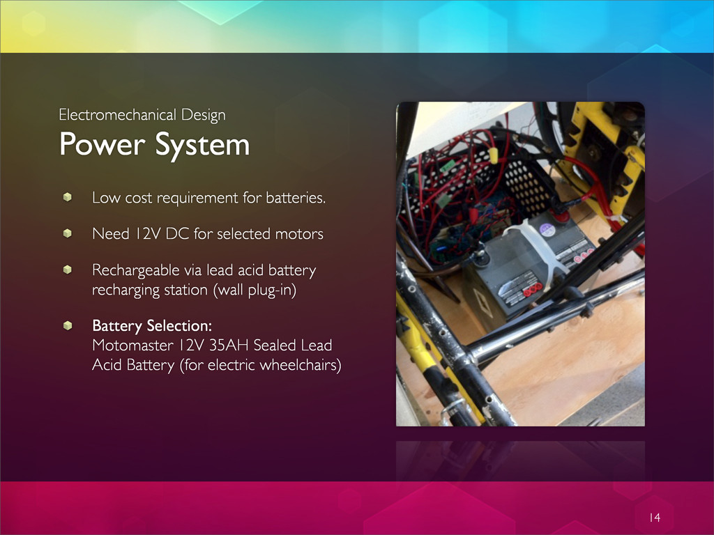
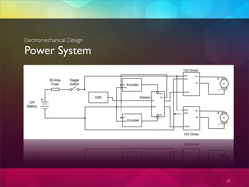
motors Rechargeable via lead acid battery recharging station (wall plug-in) Battery Selection: Motomaster 12V 35AH Sealed Lead Acid Battery (for electric wheelchairs) 14 Electromechanical Design Power System
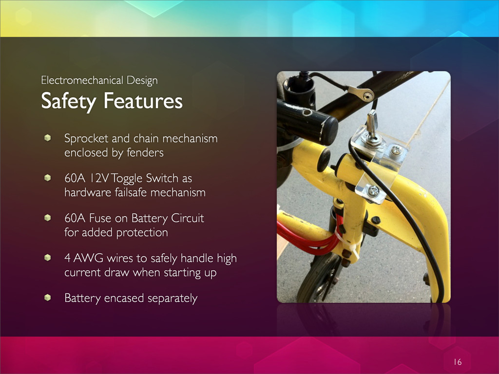
Switch as hardware failsafe mechanism 60A Fuse on Battery Circuit for added protection 4 AWG wires to safely handle high current draw when starting up Battery encased separately 16 Electromechanical Design Safety Features
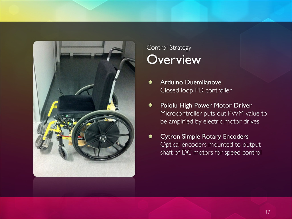
High Power Motor Driver Microcontroller puts out PWM value to be amplified by electric motor drives Cytron Simple Rotary Encoders Optical encoders mounted to output shaft of DC motors for speed control 17
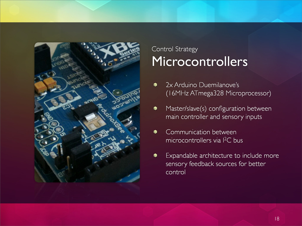
configuration between main controller and sensory inputs Communication between microcontrollers via I2C bus Expandable architecture to include more sensory feedback sources for better control 18
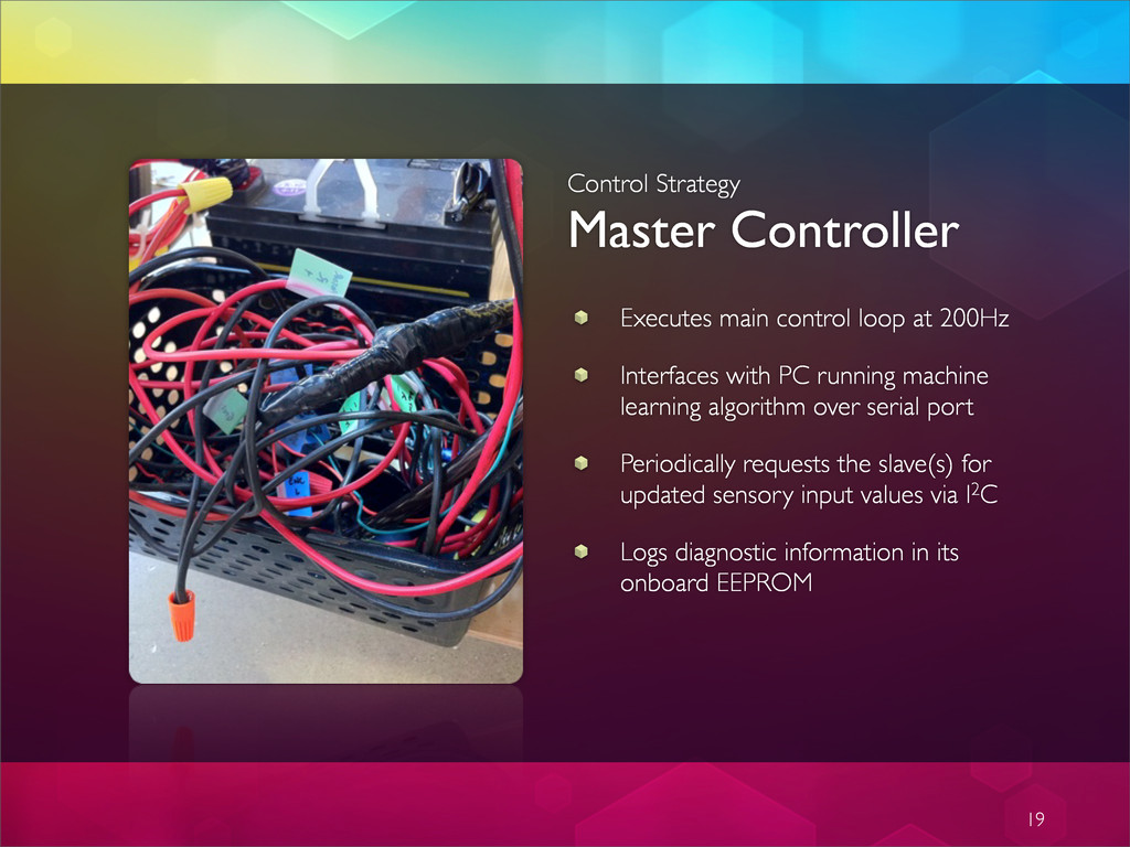
Interfaces with PC running machine learning algorithm over serial port Periodically requests the slave(s) for updated sensory input values via I2C Logs diagnostic information in its onboard EEPROM 19
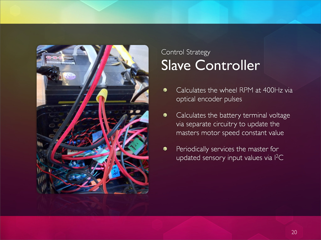
via optical encoder pulses Calculates the battery terminal voltage via separate circuitry to update the masters motor speed constant value Periodically services the master for updated sensory input values via I2C 20
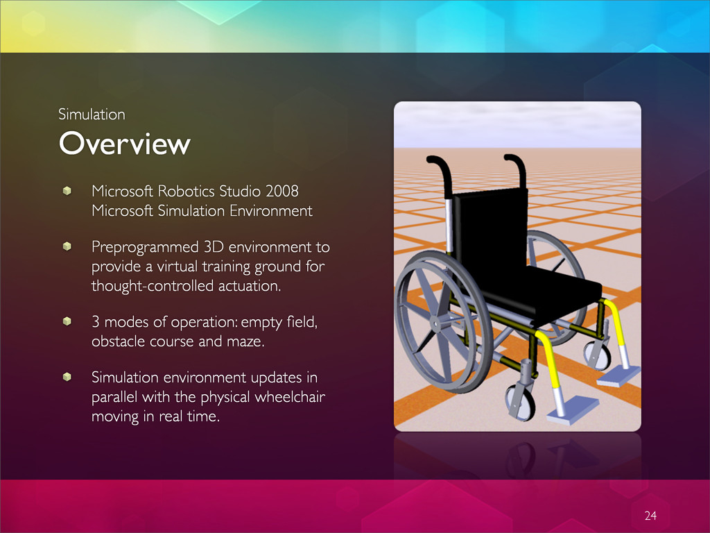
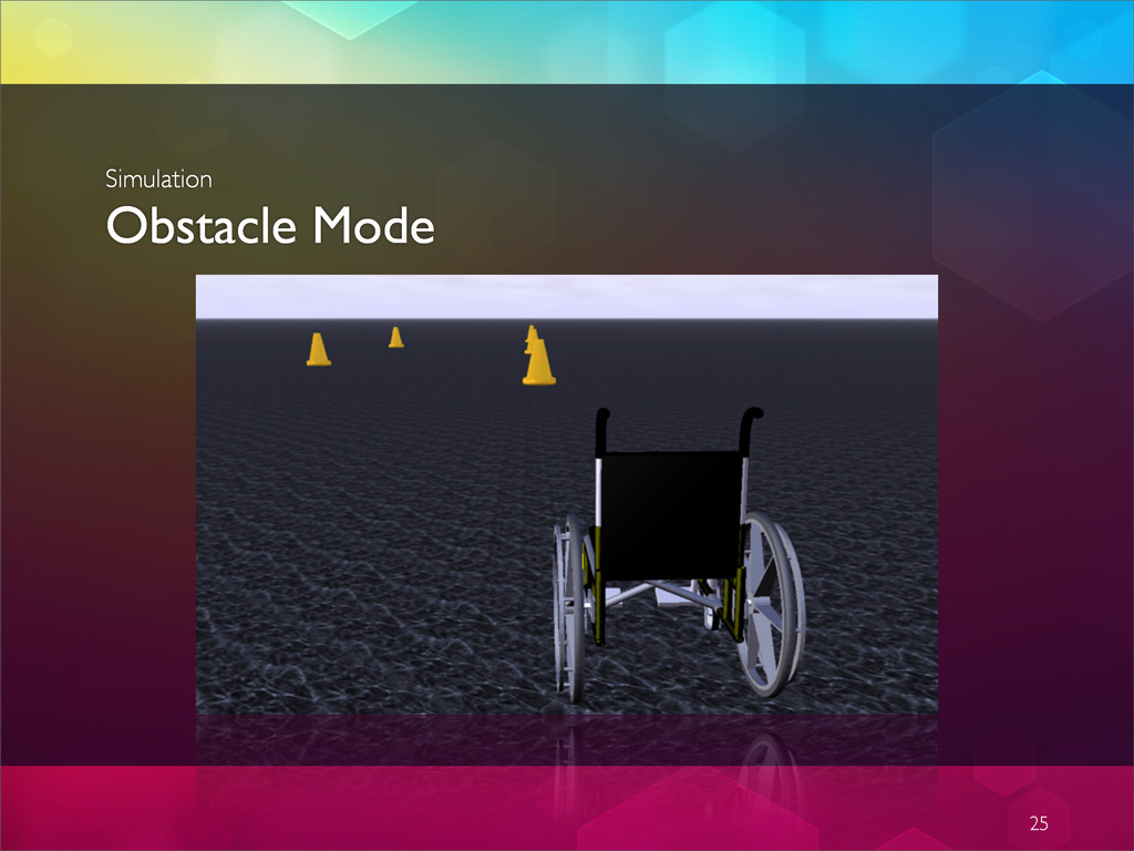
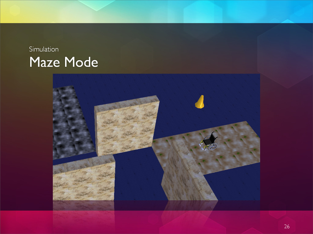
to provide a virtual training ground for thought-controlled actuation. 3 modes of operation: empty field, obstacle course and maze. Simulation environment updates in parallel with the physical wheelchair moving in real time. 24 Simulation Overview
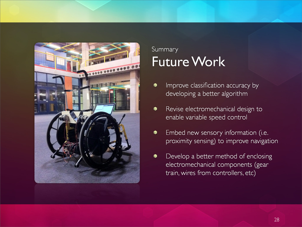
algorithm Revise electromechanical design to enable variable speed control Embed new sensory information (i.e. proximity sensing) to improve navigation Develop a better method of enclosing electromechanical components (gear train, wires from controllers, etc) 28